Electrochemical trepanning with an auxiliary electrode
Ting JIANG, Dong ZHU, Gaopan LEI
National Key Laboratory of Science and Technology on Helicopter Transmission, Nanjing University of Aeronautics and Astronautics, Nanjing 210016, China
KEYWORDS Aero-engine;Auxiliary electrode;Current density;Electrochemical trepanning;Stray corrosion
Abstract Electrochemical trepanning(ET)is one of the main methods for processing the blisks in aero-engines. However,stray corrosion in ET has a very negative impact on the machining quality of the blades.This paper proposes an innovative ET method with an auxiliary electrode surrounding the inner wall of the cavity above the cathode.Two-dimensional electric-field models are established and simulations are carried out with the auxiliary electrode at different positions and different electric potentials. The electric-field simulations show that adding the auxiliary electrode reverses the directions of the current lines in the processed area, thereby protecting it. The results show that when the distance from the bottom of the auxiliary electrode to the top of the cathode tool is 3 mm and the potential difference between the auxiliary electrode and the anode workpiece is 5 V,the area corroded by stray current is decreased.Experiments are performed under the parameter values determined by the simulations,and they confirm that this method is effective at reducing stray corrosion. Specifically, at a feed rate of 2.5 mm/min, the blade taper angle is decreased from 1.37° to -0.09°, the thickness of the leading and trailing edges is increased from 0.307 mm to 0.704 mm, and the average surface roughness is decreased from Sa =8.239 μm to Sa=7.028 μm.©2020 Chinese Society of Aeronautics and Astronautics.Production and hosting by Elsevier Ltd.This is an open access article under the CC BY-NC-ND license(http://creativecommons.org/licenses/by-nc-nd/4.0/).
1. Introduction
A blisk is one of the key components of an aero-engine.1To achieve low pressure loss, high thrust-to-weight ratio, and a high level of reliability, an aero-engine places high demands on the manufacturing of its blisks.2To meet these high performance requirements, monolithic blisks are usually made of difficult-to-machine materials such as nickel-based superalloys and titanium alloys,3and it is difficult for traditional machining method to process such materials economically and efficiently. Compared with traditional machining methods,electrochemical machining (ECM) has the unique advantages of no tool wear and no residual mechanical stress.4-6In the process of ECM, the anode workpiece, namely the blade, is connected to the positive pole of the power supply, and the cathode tool is connected to the negative pole. Consequently,there is a potential difference between the anode workpiece and the cathode tool,the presence of which(as well as conductive electrolyte) leads to the formation of a conductive circuit between the anode workpiece and the cathode tool.7,8Based on the electrochemical principle, the anode workpiece dissolves. While dissolution in the processing area is intended,that in the non-processing area is generally known as stray corrosion and has a very negative impact on the machining quality of the anode workpiece,such as poor surface roughness and low shape accuracy, among other problems.
Various research efforts have been devoted to diminishing stray corrosion in ECM. De Silva, et al.9showed that using a low-concentration passive electrolyte can improve the localization of electrochemical dissolution. Fan, et al.10improved that localization in the processing area by setting a magnetic field perpendicular to the electric flux, thereby reducing stray corrosion in the non-processed areas. In laser-assisted jet ECM, Pajak, et al.11reported that the high-temperature parts dissolved quickly which is sprayed by the Electrolyte jet combined with laser beam, thereby reducing the dissolution in unwanted area and improving processing accuracy. Li, et al.12achieved localized dissolution through a new horizontal machining mode in which the jet electrolyte hits the workpiece surface horizontally; gravity reduces re-contact between the cathode nozzle and the reflected electrolyte, thereby reducing stray corrosion. In electrochemical drilling machining, Fang,et al.13showed that using an auxiliary electrode plate improved the exit accuracy of the holes, and they used this method to machine multiple holes. Wang, et al.14showed that the adhesion of the conductive coating on the rotating cathode surface is better than that of the insulating coating,which is more conducive to suppressing stray corrosion in counter-rotating ECM. Gu, et al.15proposed an optimized method of electrochemical trepanning(ET)with a pictographic insulation sleeve embedded in the cathode cavity;this method reduced the taper angle of the blade by decreasing the side gap. To reduce stray corrosion,Hu,et al.16proposed ET with gas film insulation,in which the processed blade is surrounded by air to remove stray electrolyte.
Among a series of ECM processes, ET has become one of the main processing methods in the manufacture of aeroengine blades.17However,stray corrosion is a prominent problem in ET. To reduce the stray corrosion of blades machined by ET effectively, this paper proposes an innovative method in which an auxiliary electrode surrounds the inner wall of the cavity above the cathode. With the feed of the cathode tool,the shaped blade is continuously get into the cavity above the cathode.The auxiliary electrode is applied with a potential higher than that of the anode workpiece,and more power lines are concentrated at the auxiliary electrode, thereby protecting the machined area. The validity and feasibility of the method are assessed by simulations and experiments, respectively.
2. Principle of electrochemical trepanning with an auxiliary electrode
Conventional ET is shown schematically in Fig.1(a).The current direction is fully from the anode workpiece to the cathode tool.Based on the electrochemical principle of anodic dissolution, there is unexpected stray corrosion in the processed part of the blade, resulting in defects such as a large taper angle,uneven leading and trailing edges, and poor surface quality,among others.
The proposed ET with an auxiliary electrode is shown schematically in Fig.1(b).The outer wall of the auxiliary electrode sheet is attached closely to the inner wall of the insulation cavity, and they are similar in shape. Because of a higher potential on the auxiliary electrode than on the anode workpiece, some power lines are concentrated at the auxiliary electrode. Some of the power lines are from the auxiliary electrode to the processed area of the blade, and the others are from the auxiliary electrode to the cathode tool.The directions of the power lines of the processed area are reversed, thereby reducing the unexpected stray current in the machined area.
Let H be the distance from the bottom of the auxiliary electrode to the top of the cathode tool, and let ΔU be the potential difference between the auxiliary electrode and the anode workpiece. Both H and ΔU may affect the distribution of the electric field, which in turn determines the distribution of the stray current. To investigate how H and ΔU influence the electric-field distribution, a single-factor method is adopted herein for simulation and analysis,and a suitable combination of these two parameters is used for the corresponding experiments.
3. Simulations
3.1. Electric-field model and boundary conditions
To explore how H and ΔU influence the electric-field distribution in ET with an auxiliary electrode, the following simulations were carried out.
3.1.1. Establishment of electric-field model
The three-dimensional model of ET with an auxiliary electrode is shown in Fig.2(a).The cathode feeds toward the workpiece,which in the processing area is shaped by electrochemical dissolution. To explain clearly the electrolyte flow model, Fig. 2(b)shows cross-section A in Fig.2(a).The flow pattern shown in Fig. 2 (b) is forward flow, which is one of the most commonly used electrolyte flow modes in ET.The electrolyte flows into the processing area from two inlet channels on both sides of the blade,and then it flows out of the processing area freely.This method of ET with an auxiliary electrode can be applied to almost every type of straight blade with equal cross section in ET.To simplify the simulation,the two-dimensional(2D) cross-section B in Fig. 2 (a) is selected as the simulation plane. Fig. 3 (a) and (b) show the 2D electric-field simulation models for conventional ET with no auxiliary electrode and ET with an auxiliary electrode, respectively.
3.1.2. Boundary conditions
The electric field in the inter-electrode gap satisfies Laplace’s equation13,18

where φ is the electric potential in the inter-electrode gap,and x and y are Cartesian coordinates on the 2D plane.
The cathode tool and anode workpiece are two equipotential surfaces,and the anode workpiece is connected to the positive pole of the power supply, giving:
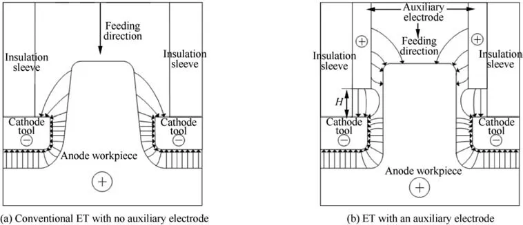
Fig. 1 Schematics of power line distribution in electrochemical trepanning (ET).
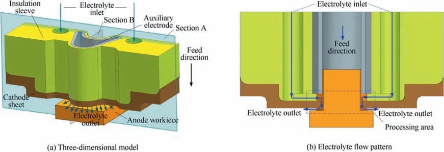
Fig. 2 Schematics of three-dimensional model and electrolyte flow pattern in ET with an auxiliary electrode.
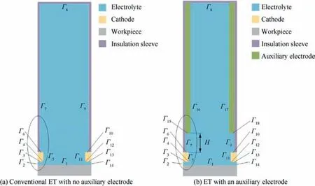
Fig. 3 Two-dimensional (2D) electric-field models.

where Uwis the electric potential on the surface of the anode workpiece.The cathode tool is connected to the negative pole of the power supply, giving:

The free boundaries can be regarded as approximate insulation, giving:

And the other boundaries are insulated perfectly, giving:

Eqs. (2)-(5) are the boundary conditions for conventional ET.For ET with an auxiliary electrode,there is the additional boundary condition:

where Uais the electric potential on the surface of the auxiliary electrode.
3.2. Simulations and analysis of results
All the electric-field simulations were performed with the above models in the software package COMSOL version 5.4.The simulations were performed with different values of H and ΔU because these two parameters influence the electricfield distribution considerably.Each simulation was a dynamic process of the cathode feeding to the anode workpiece with an initial gap of 0.5 mm. Considering the efficiency and safety based on processing experience, the simulations adopted a cathode feed rate of 2.5 mm/min. The electric potential of the anode workpiece was set to 22 V. According to the actual processing requirements, the feed depth of the cathode was 9 mm. The cathode sheet was designed to be 1.5 mm thick.The values of all the simulation parameters are given in Table 1. These simulations adopted the single-factor method,the flow chart of which is shown in Fig. 4. First, the value of ΔU was set to 5 V and simulations were carried out at H=3, 4.5, and 6 mm. How the value of H influenced the electric-field distribution was then analyzed to give the optimal value of H. Next, with that value of H, simulations were performed at ΔU=1, 3, 5, 7, and 9 V. How ΔU influenced the electric-field distribution was analyzed to give the suitable value of ΔU. Finally, the selected combination of H and ΔU was used in the subsequent verifying experiments.
3.2.1. Influence of auxiliary-electrode position on electric-field distribution
Simulations were carried out at H=3, 4.5, and 6 mm for ΔU=5 V. The distribution of current density on one side of the blade at the last moment of dynamic simulation is shown in Fig. 5. The positive direction of the horizontal axis represents the direction from the root to the tip of the blade, andthe vertical axis represents the value of the current density.The current density flowing into the anode workpiece is defined as a negative value, and that flowing out of the anode workpiece is defined as a positive value.Negative current density protects the workpiece, whereas positive current density dissolves it.The distributions of current density are as follows.(1)In conventional ET,the current density near the root of the blade is high, indicating that high current density in the processing area helps to dissolve the workpiece. From the root to the tip of the blade, the current density decreases and the current-density curve flattens.The farther from the processing area, the lower the current density, and stray corrosion is caused by low current density.(2)When an auxiliary electrode is applied, the current density in the processing area is high.However, the current density decreases to zero at a certain point on the blade and then becomes negative, thereby suppressing stray corrosion and protecting the blade.

Table 1 Values of simulation parameters.
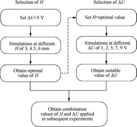
Fig. 4 Flow chart of single-factor method.
To observe clearly the distribution of power lines near the point where the current density becomes zero, Fig. 6 shows locally enlarged plots of the current-density distribution in the areas marked in Fig. 3 and the positions of the reversal points are indicated by the dashed horizontal line. The color scale is set to 0-3 V for H=6 mm and to 0-10 V for the rest.
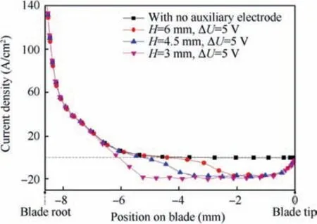
Fig. 5 Distribution of current density on one side of workpiece for different values of H.
The distributions of current density are as follows. As H decreases, the current density between the auxiliary electrode and the cathode tool increases and more power lines are attracted by the auxiliary electrode. For H=6 mm, the coordinate of the point where the current density becomes zero is approximately-4.5 mm. When H is reduced to 4.5 mm, the coordinate of the reversal point is approximately-5.3 mm,closer to the root of the blade. When H is reduced to 3 mm,the coordinate of this point is closest to the root of the blade,at approximately-6.05 mm, indicating the smallest area affected by stray corrosion.It can be concluded that the smaller H, the closer is the root of the blade to where the current density becomes negative. Considering the specific position of the electrolyte inlet which is set under the auxiliary electrode, the minimum H value selected in this paper is 3 mm.
3.2.2. Influence of potential difference on electric field distribution
Follow-up simulations were performed at ΔU=1,3,5,7,and 9 V for H=3 mm based on the previous simulation results.Fig. 7 shows the distribution of current density on one side of the blade at the last moment of the dynamic simulation.The current density remains positive in conventional ET, but in ET with an auxiliary electrode there is a zero point where the current density turns negative.
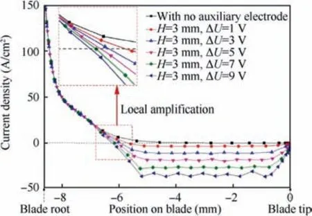
Fig. 7 Distribution of current density on one side of workpiece at different values of ΔU.
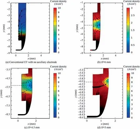
Fig. 6 Distribution of power lines on one side of blade in conventional ET and ET with auxiliary electrode at different values of H.
Locally enlarged plots of the current-density distribution in the areas marked in Fig. 3 are shown in Fig. 8. The color scale is set to 0-10 V. As shown in Fig. 8, when ΔU=1 V,the coordinate of the point where the current density becomes negative is approximately -5.7 mm. When ΔU=3 V, the coordinate of the reversal point is approximately -5.9 mm. When ΔU=5 V, the coordinate of the reversal point is approximately -6.05 mm, closer to the root of the blade. For ΔU=7 V and 9 V, the coordinate of the reversal point is approximately -6.15 mm and -6.25 mm,respectively, which are close to the values when ΔU=5 V.The larger the value of ΔU, the closer the reversal point to the blade root and the smaller the coordinate value of the reversal point. As the value of ΔU is increased, coordinate value of the reversal point changes by less and less. Therefore, we selected ΔU=5 V for use in the following experiments.
4. Experiments and results
To assess the validity of the simulation results, comparative ET experiments were carried out without and with an auxiliary electrode.
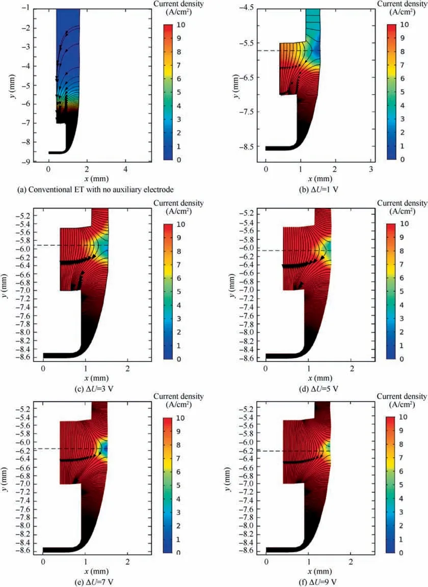
Fig.8 Distribution of power lines on one side of blade in conventional ET and ET with an auxiliary electrode at different values of ΔU.
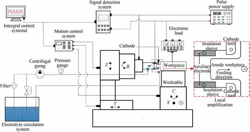
Fig. 9 Experimental system for ET with an auxiliary electrode.
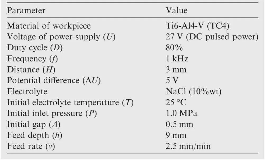
Table 2 Experimental parameters.
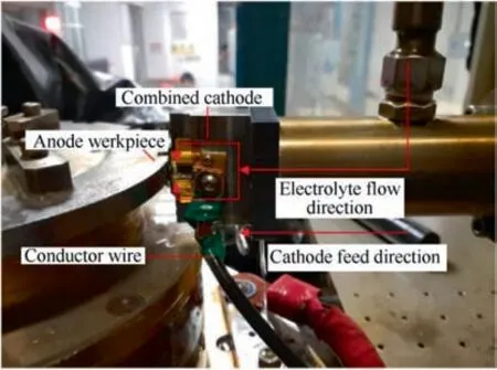
Fig. 10 Machining site.
4.1. Experimental set up
The system used in the experiments is shown in Fig. 9. In ET with an auxiliary,the anode workpiece is fixed on the rotating worktable, and the cathode tool feeds to the anode workpiece in a straight line at constant speed. The electrolyte flow mode is forward flow, as shown in Fig. 2 (b). The electrolyte flows from both sides near the leading and trailing edges and converges in the processing area, with an open electrolyte outlet.
The material of workpiece was TC4 alloy. The voltage of the DC pulsed power supply was set to 27 V, corresponding to ΔU=5 V. The duty cycle and the frequency were 80%and 1 kHz, respectively. The initial machining gap was 0.5 mm and the initial inlet pressure was 1.0 MPa. The electrolyte used in the experiment was 10% NaCl with an initial electrolyte temperature of 25°C. Considering the safety and efficiency during actual processing, most of the experiments were carried out at a cathode feed rate of 2.5 mm/min. All the parameter values used in the experiments are given in Table 2, and the machining site is shown in Fig. 10.
The circuit diagrams of the experiments are shown in Fig. 11. As shown in Fig. 11 (a), in conventional ET with no auxiliary electrode, there is only one circuit and the currentis detected by an ammeter in the experiments. In ET with an auxiliary electrode, the electronic load is in series with the anode workpiece and in parallel with the auxiliary electrode,which is shown in Fig. 11 (b). Because of voltage sharing of the electronic load, the electric potential on the surface of the auxiliary electrode is higher than that of the anode workpiece, and the potential difference is the voltage drop at the electronic load. Here, I0is the current of the main circuit, I1and I2are the currents flowing into the electronic load branch and the auxiliary electrode branch, respectively, I3is the current flowing from the anode workpiece to the cathode tool,I4is the current flowing from the auxiliary electrode to the cathode tool, and I5is the current flowing from the auxiliary electrode to the anode workpiece. Of these,I0and I1were detected by ammeters during the experimental processing.
In conventional ET with no auxiliary electrode,represents the current flowing from the anode workpiece to the cathode tool,including machining current in the processing area and unwanted stray current in the processed area. In ET with an auxiliary electrode, I3represents the current flowing from the anode workpiece to the cathode tool, also including machining current in the processing area and unwanted stray current in the processed area.
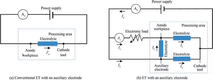
Fig. 11 Circuit diagrams.
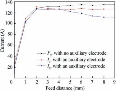
Fig.12 Variation of typical currents in ET with and without an auxiliary electrode.
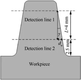
Fig. 13 Schematic of taper angle in ET.
Fig.12 shows how the current varies.(1)When the feed distance reaches approximately 2 mm, the processing enters an equilibrium state. I0(about 125 A) is less than I′0 (135 A). It can be seen from Fig. 11 (b), I0is the sum of I3and I4, so I3is less thanIn other words, in ET with an auxiliary electrode, the current flowing from the anode workpiece to the cathode tool (I3) is less than that (in conventional ET.According to Faraday’s law, less current means less material removal.Therefore,the smaller I3in ET with an auxiliary electrode means less stray current than I′0 in conventional ET. (2)In ET with an auxiliary electrode, when the feed distance reaches approximately 4 mm, I1begins decreasing down to approximately 110 A at the feed distance of 9 mm. This is because as the cathode tool feeds, more part of the anode workpiece is surrounded by the auxiliary electrode and the processed area is better protected.
4.2. Experimental results
4.2.1. Effects of auxiliary electrode on taper angle of blade
The taper angle γ is an important index for judging the quality of ET, where γ is calculated as:19

As shown in Fig. 13, dwis the width deviation of the sections cut by detection lines 1 and 2 separated by the distance L. The theoretical height of the blade is 8.6 mm. Because of the arcs on the blade tip and root, the lower detection line is 2.5 mm from the blade root and L=4 mm.
A set of comparative experiments was performed at a feed rate of 2.5 mm/min. The results shown in Fig. 14 (a) and (b)are sections of the machined workpieces consistent with the simulation model and observed using an optical microscope(DVM 5000; Leica, Germany). Using an auxiliary electrode decreased the blade taper angle from 1.37° to -0.09°.
An additional set of comparative experiments was performed at a feed rate of 0.5 mm/min but with all other parameters the same.The results are shown in Fig.14(c)and(d).The blade taper angle now decreased from 7.70°to-1.09°,indicating that using an auxiliary electrode is effective for suppressing stray corrosion and reducing the blade taper in ET.
4.2.2. Effects of auxiliary electrode on profiles of leading and trailing edges
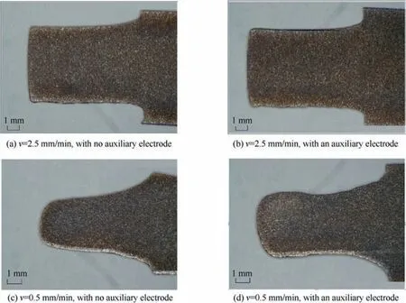
Fig. 14 Mid-sections of machined workpieces.
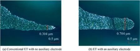
Fig. 15 Magnified views of leading edge of blade.
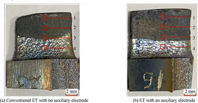
Fig. 16 Surfaces of processed workpieces.
Because stray corrosion affects the formation of the leading and trailing edges, the blade leading edge was detected and analyzed. A toolmaker’s microscope (STM7-SFA; Olympus,Japan) was used to obtain magnified views of blade leading edges and measure their thickness at similar positions, as shown in Fig.15.With conventional ET,the profile of leading edge is uneven and cannot form expected circular arc; here,stray corrosion has a serious effect, shaping a 0.304 μm-thick sharp corner. When an auxiliary electrode is used, the sharp corner tends to be more rounded; the thickness of the leading edge increases to approximately 0.704 μm, more than double that with conventional ET.
According to basic physical principles, the equipotential surfaces are dense and the electric field is high where the surface curvature is large.As the parts with the largest blade curvature, the electric field is concentrated at the leading and trailing edges, and stray corrosion is more severe there than elsewhere.20,21When an auxiliary electrode was applied with a higher electric potential than that of the anode workpiece,the power lines on the workpiece were attracted by the auxiliary electrode, thereby reducing the concentrated electric field at the leading and trailing edges.Thus,compared with conventional ET,using an auxiliary electrode improves the formation of the leading and trailing edges by reducing electric-field concentration.
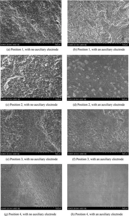
Fig. 17 Scanning-electron-microscope photographs of surface morphologies of machined workpieces at different positions.
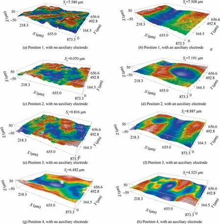
Fig. 18 Optical-profiler-microscope photographs of surface morphology machined workpieces at different positions.
4.2.3. Effects of auxiliary electrode on surface quality of blade
Stray corrosion also affects the quality of the machined surface.Using an auxiliary electrode changes the electric-field distribution of the processed area, thereby changing its surface quality. Therefore, the surface topography was detected to study how it was affected by the auxiliary electrode.For observational convenience, each workpiece processed either with or without an auxiliary electrode was cut into the shape shown in Fig. 16. Four evenly distributed locations on the surfaces of the processed workpieces were selected for measurement,detected by a scanning electron microscope (S-3400 N; Hitachi, Japan) and an optical profiler (S Neox; Sensofar, Spain).The photographs are shown in Figs. 17 and 18, respectively.
As shown in Fig. 17, the characteristics of the machined surfaces are as follows. (1) With conventional ET, the processed surface of the workpiece has a deeper and denser texture; by contrast, with ET with an auxiliary electrode, the processed surface has a lighter and sparser texture.(2)The surface quality of position 4,which is near the blade root,is better than that elsewhere on the blade.
The surface morphology and value of surface roughness at different positions are shown in Fig.18.The sampling range of the surface detected by the optical profiler was 873.33 μm×656.61 μm. With no auxiliary electrode, the surface color is disordered and the average surface roughness is Sa=8.239 μm,which means that the surface is rough. By contrast, the more-uniform color distribution with an auxiliary electrode means a smoother surface, with an average surface roughness of Sa=7.028 μm.
We draw the following conclusions from the results. (1)Using an auxiliary electrode in ET is effective for suppressing stray corrosion,improving surface quality,and decreasing surface roughness on the processed surfaces of the workpiece,indicating the effectiveness of the previous simulation. (2) In ET with or without an auxiliary electrode, the surface quality near the blade root is better than that elsewhere on the blade.In many ECM processes, stray corrosion usually occurs in areas where the current density is less than 5 A/cm2, thereby reducing the surface quality.5,13,18,22Herein, the stray current density near the blade root is higher than that elsewhere on the blade and exceeds 5 A/cm2, based on the previous simulation results.Therefore,compared with elsewhere on the blade,the influence of stray corrosion near the blade root is less and the surface quality is better.
5. Conclusions
(1) An innovative method was proposed of ET with an auxiliary electrode applied in the machining of aero-engine blades, leading to less stray corrosion in the machined parts of the blade.
(2) Two-dimensional electric-field models were established,and simulations were performed with different values of H and ΔU. The results show that using an auxiliary electrode protects the anode workpiece by changing the current direction in the processed area. With H=3 mm and ΔU=5 V, the machined area was protected effectively.
(3) Experiments were performed with H=3 mm and ΔU=5 V as determined by the simulation results. The experiments validated the simulation results. The experimental results showed that using an auxiliary electrode is effective at reducing the taper angle from 1.37°to-0.09°, increasing the thickness of the leading and trailing edges from 0.307 mm to 0.704 mm,and improving the surface quality of the blade by reducing the average surface roughness from Sa=8.239 μm to Sa=7.028 μm.
Declaration of Competing Interest
The authors declare that they have no known competing financial interests or personal relationships that could have appeared to influence the work reported in this paper.
Acknowledgement
This study was co-supported by the National Natural Science Foundation of China (No. 91860135), the National Natural Science Foundation of China for Creative Research Groups(No. 51921003) and the National Key Laboratory of Science and Technology on Helicopter Transmission(Nanjing University of Aeronautics and Astronautics, No. HTL-A-20G07).
 CHINESE JOURNAL OF AERONAUTICS2021年5期
- CHINESE JOURNAL OF AERONAUTICS的其它文章
- Ferrofluid moving thin films for active flow control
- Preliminary study on heat flux measurement data of TT-0 flight test
- An analysis and enhanced proposal of atmospheric boundary layer wind modelling techniques for automation of air traffic management
- Jet sweeping angle control by fluidic oscillators with master-slave designs
- Hot deformation behavior and microstructure evolution of the laser solid formed TC4 titanium alloy
- A method for automatic detection and characterization of plasma bubbles using GPS and BDS data
