Deep learning enabled localization for UAV autolanding
Minghui LI, Tianjiang HU
Machine Intelligence and Collective RObotics (MICRO) Lab, Sun Yet-sen University, Guangzhou 510275, China
KEYWORDS Deep learning;Localization;Safe landing;Stereo vision;UAV autolanding
Abstract This article concentrates on ground vision guided autonomous landing of a fixed-wing Unmanned Aerial Vehicle (UAV) within Global Navigation Satellite System (GNSS) denied environments.Cascaded deep learning models are developed and employed into image detection and its accuracy promoting for UAV autolanding, respectively. Firstly, we design a target bounding box detection network BboxLocate-Net to extract its image coordinate of the flying object. Secondly,the detected coordinate is fused into spatial localization with an extended Kalman filter estimator.Thirdly,a point regression network PointRefine-Net is developed for promoting detection accuracy once the flying vehicle’s motion continuity is checked unacceptable. The proposed approach definitely accomplishes the closed-loop mutual inspection of spatial positioning and image detection,and automatically improves the inaccurate coordinates within a certain range.Experimental results demonstrate and verify that our method outperforms the previous works in terms of accuracy,robustness and real-time criterions.Specifically,the newly developed BboxLocate-Net attaches over 500 fps, almost five times the published state-of-the-art in this field, with comparable localization accuracy.
1. Introduction
In the past few decades, Unmanned Aerial Vehicles (UAVs)have drawn more and more research attention due to their remarkable characteristics, such as low risk of casualties, low cost,lightweight,and great mobility associated with adaptability to dirty, dull and/or dangerous situations. UAVs have,therefore, been applied to a variety of scenarios, including meteorological detection, local area monitoring, survey and mapping, forest fire prevention, earthquake rescue1and many more. With the integration of advanced automation technology, unmanned vehicles can perform regular-cruise tasks with quite little manual intervention, since the task workspace is almost wide when the vehicle is flying in the air. However,take-off and/or landing is still a technological challenge because the vehicle works in a quite compact space that has complicated relationship with the ground.Specifically,landing of the fixed-wing vehicles has been proven to be the most challenging and hazardous period of aerial flight in many practical applications.2Even minor errors in guidance or control might cause system damages or even crashes. This situation becomes more remarkable due to a variety of complex application scenarios and meteorological environment conditions.Under such circumstances, autonomous landing has been an important and essential technique for unmanned systems within unknown or Global Navigation Satellite System(GNSS)-denied scenarios.3Hereafter, autonomous landing within GNSS-denied scenarios is called as autolanding. Furthermore,this article concentrates on vision-based localization for autolanding then.
Previous research on vision-guided autonomous UAV landing can be categorized into onboard vision and ground vision modes.The onboard vision mode usually employs one or more cameras installed on the flying vehicle as a positioning sensor.4-7When the aerial vehicle approaches the ground runway,the camera detects the runway and plans an appropriate landing trajectory. In contrast, the ground vision mode distributes and fixes vision systems on the ground.8-10
Compared with onboard navigators,the ground vision system possesses more scalable computing resources and can save costs by placing them on a runway instead of configuring each vehicle separately. Furthermore, the image from the groundto-air perspective is much more convenient for processing than the images from the air-to-ground view. Therefore, in this study, we focus on the ground vision mode for autolanding of fixed-wing unmanned aircraft.
So far, several prototypes of ground vision based autonomous landing systems have been developed in Refs.8-10,respectively.All are concerned with a mapping from image sequences to spatial trajectories using computer vision which usually involves two workflow steps: flying vehicle target detection and automatic positioning. In this study, the vision automatic detection schemes are concerned and considered further. As for similar scenarios, Yang et al.8presented accurate UAV landing performance in a GPS-denied environment, by running a ground-based near infrared camera system. A nose infrared laser lamp is fixed on the vehicle as a cooperative marker for image detection. The foreground area of the candidate targets is obtained by a simple morphological pre-processing.Researchers at Portuguese Navy Research Center9used a ground based monocular vision system supporting the autonomous landing of a fixed-wing aerial vehicle onto a fast patrol boat. For obtaining the relative pose of the vehicle, they employed several 3D model-based system combinations using the Computer-Aided Design (CAD) model for tracking. Both systems need to know the geometrical model or place the cooperative marker on the flying vehicle. On the contrary, Kong et al. developed a traditional stereo ground-based system including two pan-tilt units and two cameras, without relying on any cooperative onboard marker or geometrical knowledge.10Since the system was conducted, Hu et al.3,10,11have been working on algorithms of automatic detection and localization on an autolanding vehicle. Both corner-based and skeleton-based algorithms have been designed and implemented to target detection on the ground captured sequential images.3,12Tang et al.3initially integrated the active contour method into Chan-Vese model detection,and an extended Kalman estimator was developed for ground vision based localization.Thanks to on-ground sufficient computing resources,Cao et al.13adopted and improved a flying vehicle tracking algorithm based on GOTURN, which attaches the frame rate to 100 fps, nearly 5 times higher than that of the Chan-Vese algorithm.
Although the pre-existing researches have shown remarkable detection performance in the UAV autolanding processing, challenges still exist in accuracy, robustness and realtime feature. Yang’s target detection method8is only suitable for UAVs equipped with infrared laser lamp at the nose,which is difficult to be generalized for various types of aircraft. Due to the processing rate of below 25 fps, the real-time performance of Chan-Vese is seldom appropriate for practical applications of autolanding.3Similarly, the GOTURN tracking based method13relies on human-computer interaction for labeling the bounding box within the first frame. Meanwhile,the tracking error ought to accumulate for a long-term period.Once a frame is tracked to the fall target, it may cause inefficacy of the whole vision-based tracking even. Particularly,some scenarios cannot be correctly treated by using the preexisting methods.For instance,part of the landing vehicle goes out of the field of view, and only the partial body is captured from the images.
In the consideration of the existing issues in ground vision based methods, this paper innovatively investigates a novel deep learning-based method that maps sequential image frames into the spatial localization of UAVs at the autolanding period. Deep learning supports a higher processing speed of target detection, and enables a greater accuracy promotion of vision-based positioning further.The overall algorithm has a great improvement in accuracy,robustness and real-time performance in comparison with the prior works. The contributions of this paper are summarized as follows:
(1) A light-weight convolutional deep neural network model,namely BboxLocate-Net,is proposed and implemented to perform an initial coarse prediction on spatial coordinates of the landing aircraft. The proposed BboxLocate-Net model solves the too-manyparameters-tuning problem existing in classic object detection deep networks and achieves a practical and effective balance between speed and accuracy.
(2) A spatial motion continuity criterion is defined and fused into quantitative checking on the landing target detection, by taking full advantage of the high-speed rate of the light-weight detection network.
(3) A key point regression network, namely PointRefine-Net, is developed to promote localization accuracy in the case that the flying vehicle’s motion continuity is checked unacceptable. Then, the self-correction of error detection is realized, and both robustness and accuracy are improved simultaneously.
2. Ground vision for UAV autolanding
Aimed at runway taxiing and landing of medium aerial vehicles, a ground stereo vision-based system has been developed and updated for several times.10,14-18Previous several corresponding mapping algorithms to produce the spatial trajectory of the landing vehicle have also be testified via online experiments supported by the on-ground vision system.3,10,12,13Here,we will review the ground vision system deployment and the overall workflow for the ground-to-air visual system.
2.1. System architecture and deployment
The ground stereo vision-based system usually works in the aircraft descending and taxing stages to guide it moving in the field of view to accomplish automatic landing. It usually consists of four modules: image capture module, target detection module, position calculation module and data transmission module.3,10In the image capture module, two binocular cameras are symmetrically installed on the independent Pan-Tilt Units (PTUs) to capture the landing sequential images.Each PTU with camera module works independently and has two degrees of freedom to expand the search scope. Each PTU is controlled,serves to track the landing target,and feeds the pitching and yawing angles backward.The target detection module and position calculation module are used for 2D image target detection and 3D spatial location calculation, respectively.Both of them run on the same ground image processing computer. The data transmission module transmits the calculated spatial coordinates onto the onboard autopilot via wireless data link.A general deployment scheme has been designed and implemented for ground stereo guidance prototypes, as shown in Fig. 1.
In real-scenario flights, a fixed-wing unmanned aircraft is guided into the view of the stereo camera by its onboard navigation system. Once the target is detected, the ground-based guidance system switches from the waiting state to the working mode. Two cameras capture the vehicle landing images, and then, the captured sequential images and PTU parameters are transferred to the image processing computer which detects the key point of the flight target and calculates its spatial coordinates.Finally,the spatial coordinates are wirelessly transmitted onto the onboard autopilot to facilitate autonomous landing.
In terms of deployment details,we assume that the origin of the world coordinate system(x,y,z)is at the rotation center of the left PTU, from the practical viewpoint of the published works3,10,13. The axis of the camera frame is parallel to that of the PTU frame in the initial position. The right camera is mounted on the x axis, with the light center of the left and right cameras represented as Oland Or,respectively.The baseline of the optical system is OlOr. θl, θr, αland αrrespectively represent the tilt and pan angles. The anticlockwise measurement is positive.At the same time,the hardware configuration is updated to be compatible with the deep learning requirements. The captured image is transferred to the highperformance computing platform instead of the original control computer.The GPU component performs high-load computations for flight target detection in sequential images,while the CPU is responsible for information-based positioning and wireless data transmission.
2.2. Overall workflow of vision-based localization
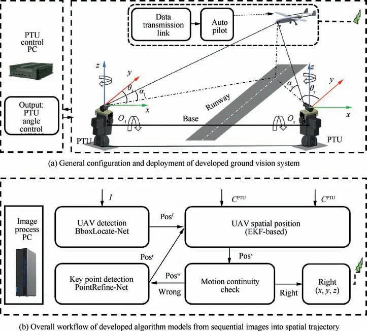
Fig. 1 Schematic diagram of ground stereo system for autonomous landing of the fixed-wing aerial vehicle.
The ground stereo vision-based localization algorithm outputs the aircraft spatial coordinates during its autolanding process,while captured sequential images and camera attitudes are inputted online. Generally speaking, the overall workflow is composed of image-based target detection and filter-based localization.
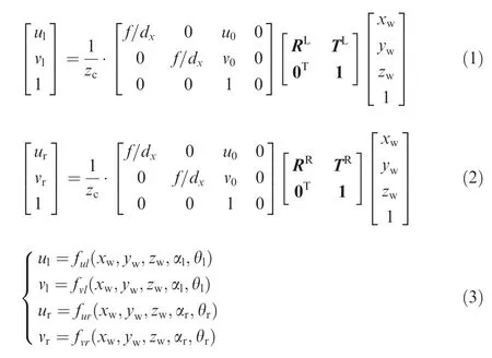
On the basis of the system described in Section 2.1,the previous positioning algorithms have been developed and verified within simulation and experimental scenarios.3The landing vehicle’s spatial coordinates are directly mapped by using the stereo measurement model, once knowing the target coordinates of the left as well as right images and the PTU attitude parameters.In details,it assumes that the UAV actual coordinate is (xw, yw, zw), and its coordinate on the left and right image plane is (ul, vl) and (ur, vr), respectively. f is the focal length of the camera. dxand dyare the pixel sizes in X and Y directions. RLand RRrepresent the rotation matrix of the world coordinate system relative to the left and right camera coordinate systems respectively. Then, the relationship of the coordinate between the 3D world and 2D image plane is calculated by
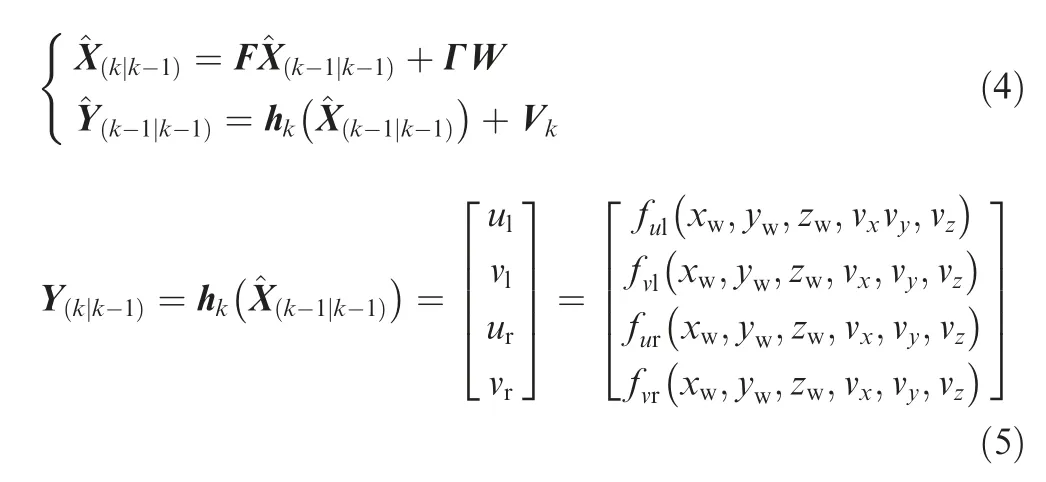
The stereo vision algorithm processes the spatial coordinates one point by one point, so random disturbance is inevitably involved in the outputted trajectory under the mentioned principle of triangulation. Tang et al.3proposed an extended Kalman filter estimator to improve localization accuracy by fusing knowledge of aircraft motion continuity. Here,X=[xw, yw, zw, vx, vy, vz]Tdenotes state variables, and Y=[ul, vl, ur, vr]Tmeans the observation values of detected target coordinates in images. By constructing the state observation equation Eq. (4) and the state estimation equation Eq.(5),the whole system state estimation process is completed through five recursive steps of extended Kalman filter.Real-scenario flight experiments have demonstrated that this method is more robust and accurate than the triangulationbased localization algorithm.3where F is a state transition matrix. Wkand Vkrepresent the system process noise and the observation noise respectively.Γ is the gain of the process noise. hkis the measurement matrix.^X(k|k-1)denotes the result predicted by the previous state.^X(k-1|k-1)is the optimal result of the previous state.^Y(k-1|k-1)means the optimal observation value of the previous state.
Eventually,this article employs deep learning models into a fast and accurate detection on the autolanding sequential images,since the pre-existing works need to be promoted with the processing rate and localization accuracy. Specifically, the proposed approach will be an original trial for the challenging scenario when the landing aircraft is partially out of the field of view.
3. Deep learning models enabling accurate and fast detection
In this study,a cascaded deep learning model is proposed and developed to enable ground vision based autolanding, with considerations on the existing challenges of real-time and accuracy. Such a scheme takes full advantage of the scalability of computing resources supported by the ground vision system.Firstly, the ground stereo mode is flexibly extendable to computing and/or storage resources. Here, we upgrade the computing platform to GTX1080ti to run the deep learning algorithm more efficiently.Secondly,annotated mixed landing datasets are conducted through a large number of actual and simulation flight experiments.Hereafter,two lightweight learning networks are developed to enable a fast and accurate detection on the autolanding vehicle. Such a hierarchical structure processes vision-based localization from coarse extraction to fine correction. Thirdly, the system scalability is both feasible and effective for improving the real-time and accuracy of the ground stereo guidance system. Finally, higher processing speed provides extra operations of motion continuity checking and coordinate correction for autolanding localization. Furthermore, the proposed two-hierarchy deep neural models are implemented, demonstrated and validated as well.
3.1. Two-hierarchy architecture of cascaded deep neural networks
A cascaded two-hierarchy convolution network is employed to make fast coarse-to-fine prediction. In the first hierarchy, we propose a bounding box regression-based convolutional network,whose input is the complete image captured by the camera. It is mainly responsible for predicting the aircraft ROI(Region-Of-Interest) coordinates in the whole image, and assuming the center point of the bounding box as the key point location. The second-hierarchy network takes the local ROI predicted by the first-hierarchy network as input,allowing only a certain range of modifications to the former coarse predictions. The inputted image size and search range keep decreasing along the cascade.
The detected bounding box certainly contains or covers the landing aircraft, but mismatching does exist between the detected box’s center and the actual image coordinates in either horizontal or vertical direction. Such mismatching phenomenon often results in localization inaccuracy of the landing vehicle.It is even worse to lead to failure of the visual positioning task. Hereafter, we introduce a second-level network to optimize the accuracy of the vision-based localization algorithm. Under such two-hierarchy architecture, the first level aims to estimate key point position robustly with few considerable errors, while the second level is designed to produce higher accuracy.
The proposed cascaded deep learning detection method consists of four stages, as shown in Fig. 2. In details,BboxLocate-Net represents the first-level network, and PointRefine-Net represents the second-level network. In the first stage, an autolanding image dataset with annotations is conducted to train the coarse detection model BboxLocate-Net.It is followed by a PointRefine-Net training process which takes lots of random small areas including key points as samples.In the third stage,the captured UAV image is detected by BboxLocate-Net. In the fourth stage, the bounding box produced by the BboxLocate-Net detection module is finally used by the point refinement module PointRefine-Net to obtain a more accurate estimation of the guiding target.
In Sections 3.2 and 3.3, we will focus on the deep neural network structure and algorithm workflow of each hierarchy.The combining strategies of cascaded two-level networks will be presented in Section 3.4.
3.2. Deep learning based target detection
The goal of detection algorithm is to locate and classify the targets during the UAV autolanding process. The detected objects are usually labeled with bounding boxes, category information and confidence score as well.
Recently, there have been more and more researches on object detection. Faster R-CNN,19the two-stage proposaldriven CNN object detector, reaches great accuracy on many challenging datasets,while the processing speed is still a major concern.Facts show that Faster R-CNN is seldom an optimal solution for real-time flying vehicle detection.YOLO v3,20the one-stage detector, not only demonstrates promising results but also yields about 10 times faster detection speed. Experimental results demonstrate that its accuracy reduces by about 12% compared to Faster R-CNN, and it still can hardly achieve real-time detection in the autolanding scenarios.
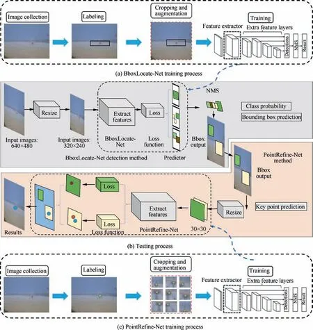
Fig. 2 Structure of detection model based on BboxLocate-Net and PointRefine-Net.
Considering the balance between accuracy and processing time, this paper proposes a novel UAV object detection network named BboxLocate-Net which is designed to create a smaller-scale, faster, and more efficient deep neural model.Without increasing the network depth and width, we address this issue from a different perspective. Using DenseNet21as a reference, we exploit the potential of the network through feature reuse and multi-scale fusion, and combine BboxLocate-Net as a feature extractor and YOLOv3 predictor. The BboxLocate-Net algorithm training and testing process are shown in Fig. 2.
We design BboxLocate-Net’s architecture based on the several principles of improving the real-time capacity and accuracy simultaneously. At first, reducing the network parameters is the key to improve the real-time performance.It is inspired by the DenseNet21network to enhance the feature reuse between layers, full use shallow and deep information,and reduce the number of parameters. The proposed network introduces a dense connection from one layer to all subsequent layers, developing a highly dense feature reuse connection among the five-layer feature maps.Different from DenseNet,21we cascade the feature maps as the decreasing order of their resolution. In this study, it is named as ‘‘Ladder-Dense”connection.
Then,the network is further designed to improve the detection accuracy. When the landing vehicle approaches and descends, the target is usually small and the background is relatively complex. The small target in the deep lowresolution feature map tends to be lost.To guarantee the accuracy of small-scale target detection, an HRNet22inspired approach is adopted to make full use of the information across all scales of the image, and reduce the loss of feature maps information due to the decrease of image resolution. Such an HRNet-inspired network works with a high-resolution subnetwork as the first parallel path, and gradually adds the other low-resolution layer’s resolution-hold parallel path one by one. As a result, the parallel path explores the network potential while maintaining resolution.In the output part of the network, a multi-scale fusion unit is deployed to cascade the information from all parallel subnetworks21to capture and integrate information at all scales of an image.
Finally, considering the real-time performance and accuracy of the detection network, the proposed BboxLocate-Net is tested with excellent performance in specified datasets. It has been noted that HRNet and DenseNet, two state-of-theart networks, have produced excellent performance in largescale dataset detection tasks such as COCO23, ImageNet24and VOC25. Specifically, the autolanding image datasets have only two classes of plane and background. The proposed BboxLocate-Net rightly achieves a balance between prediction accuracy and processing speed, by combining the advantages of DenseNet and HRNet together.
During the detection process,each image captured from the ground cameras is resized to 320×240 to match BboxLocate-Net.Then,the 20×15×18 prediction tensor is automatically generated through the feature extraction network BboxLocate-Net and the YOLO detection layer.Each of the 1×1×30 tensor includes the target location information:center coordinates(x, y), width w, height h, category information and confidence score c.20After obtaining the confidence c of each prediction box, a threshold will be set to remove the boxes with a score below. Then the remaining bounding boxes are filtered with the non-maximal suppression to obtain multiple sets of highscore bounding boxes. In particular, the YOLOv3 predictor uses a set of initial anchor boxes with fixed width and height to regress and predict the target position.Here,K-means clustering26is adopted to determine the number and the best size of anchor boxes. As shown in Fig. 3, three clustering centers are presented for the training dataset using K-means clustering. The yellow box and the blue box respectively represent two benchmark anchor boxes with different sizes. The final red box predicted by BboxLocate-Net is calculated based on three anchor boxes.
The kernel task of the BboxLocate-Net network is to calculate the object confidence value,while prediction on the width,height and central coordinates of the UAV target is concerned as well. For example, Loss values of aircraft detection generally include head frame coordinate loss Losscoorand confidence loss Lossconf. The calculation equation is as follows:

On one hand, Losscooris quantitatively analyzed by
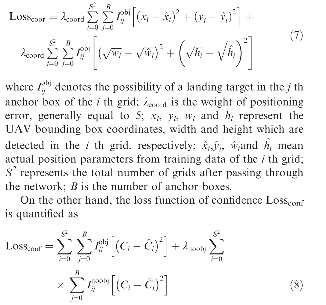
where λnoobjdenotes the weight coefficient of confidence error;Ciindicates the confidence of the target contained in the i th grid of all S2grids; ^Cirepresents the confidence parameter of the i th grid in the manually labeled data.
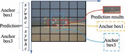
Fig. 3 Detection results based on multiple anchor boxes.
3.3. Deep learning based accuracy promoting
In the previous works of ground vision based autolanding,the detection rate of frames is not fast enough,so there is no extra time to make corrections or refinement to errors in the detection.3,13In this paper, we propose a second-level point regression network to further optimize the target’s image coordinates. The above mentioned BboxLocate-Net greatly optimizes the speed of UAV target detection and provides the possibility for the implementation of motion continuity check and coordinate correction.
For practical applications, a criterion for checking the motion continuity is necessary to determine whether or not to conduct an accuracy promoting algorithm. In this paper,we synthesize the distance and angle indexes into the motion continuity criterion.We define F(xi,yi)as the candidate point.P(x1,y1)and Q(x2,y2)denote the last two points of the UAV trajectory, and |FQ| denotes the space distance between point F and point Q. Then when the following two conditions are satisfied at the same time, F is regarded as correct. Otherwise,it is confirmed to be mismatched and has to be corrected,so we have the following equation:

The PointRefine-Net’s architecture is designed in the attempt to improving the real-time capacity and detection accuracy. Since the input of the second-level network is only a small part of the original image, we design a resolution preserving point regression network. The feature extraction network is basically the same as the sequential path part of BboxLocate-Net.However,the difference between them is that the resolution of the first few layers changes from high to low in BboxLocate-Net but stays the same in PointRefine-Net. In the shallow layers, for encouraging feature reuse, the front layer of feature extraction network of PointRefine-Net uses dense connection. In the deep layers, to effectively process and consolidate features across scales, we choose to use a single pipeline with skip layers to preserve spatial information at each resolution which is proposed in Hourglass.27
Finally, the first five layers of PointRefine-Net are connected with Dense-connection, and the output part with Hourglass-connection27. Based on the structure, PointRefine-Net becomes a simple, minimal deep learning detection network that has the capacity to capture all of these features and bring them together to output pixel-wise predictions.
In the process of key point detection, the input of PointRefine-Net is an inaccurate bounding box containing UAV target detected by BboxLocate-Net network. After the image resolution is resized to 30×30, the convolution operation is carried out. The output tensor only contains the key point coordinate information(x,y).Fig.4 shows the optimization process of PointRefine-Net from the inaccurate bounding box detected by BboxLocate-Net to the accurate point. The red dot is a wrong detection result. The green dot indicates the corrected result.
The single task of PointRefine-Net network is to predict the key point coordinate vector. For a UAV head key point, Eq.(11) is the loss function of the head key point regression task.

where xiand yirepresent the center coordinates of the predicted i th grid; ^xiand ^yistand for actual position parameters from training data of the i th grid.
3.4. Vision-based localization algorithm and workflow
Combining with Section 2.2 and the detailed description of the cascaded detection models,we are ready to present our overall localization algorithm flowchart. When actually detecting the UAV target, first, the BboxLocate-Net network receives the complete image and predicts the bounding box coordinate of the UAV target. Then, combining with PTUs parameters, we calculate the UAV spatial position based on EKF-based object spatial localization algorithm3and check the motion continuity. If the coordinate is identified as an error point, we take the local ROI predicted by the BboxLocate-Net as the input of second-level network. Finally, PointRefine-Net can precisely correct the key point coordinates in this ROI.The details are shown in Table 1.
4. Cascaded deep learning model based detection experiment
To evaluate the performance of the proposed novel target detection method,we compare the image detection results with the trajectory data collected in flight experiments. The data were obtained in a large number of UAV landing mixed images generated by a simulation platform and a real flight experimental platform. In addition, we design the following two groups of experiments to compare the proposed model with other classical detection algorithms in terms of real-time performance and detection accuracy.
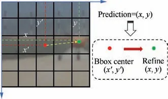
Fig. 4 Schematic diagram of error coordinate correction.
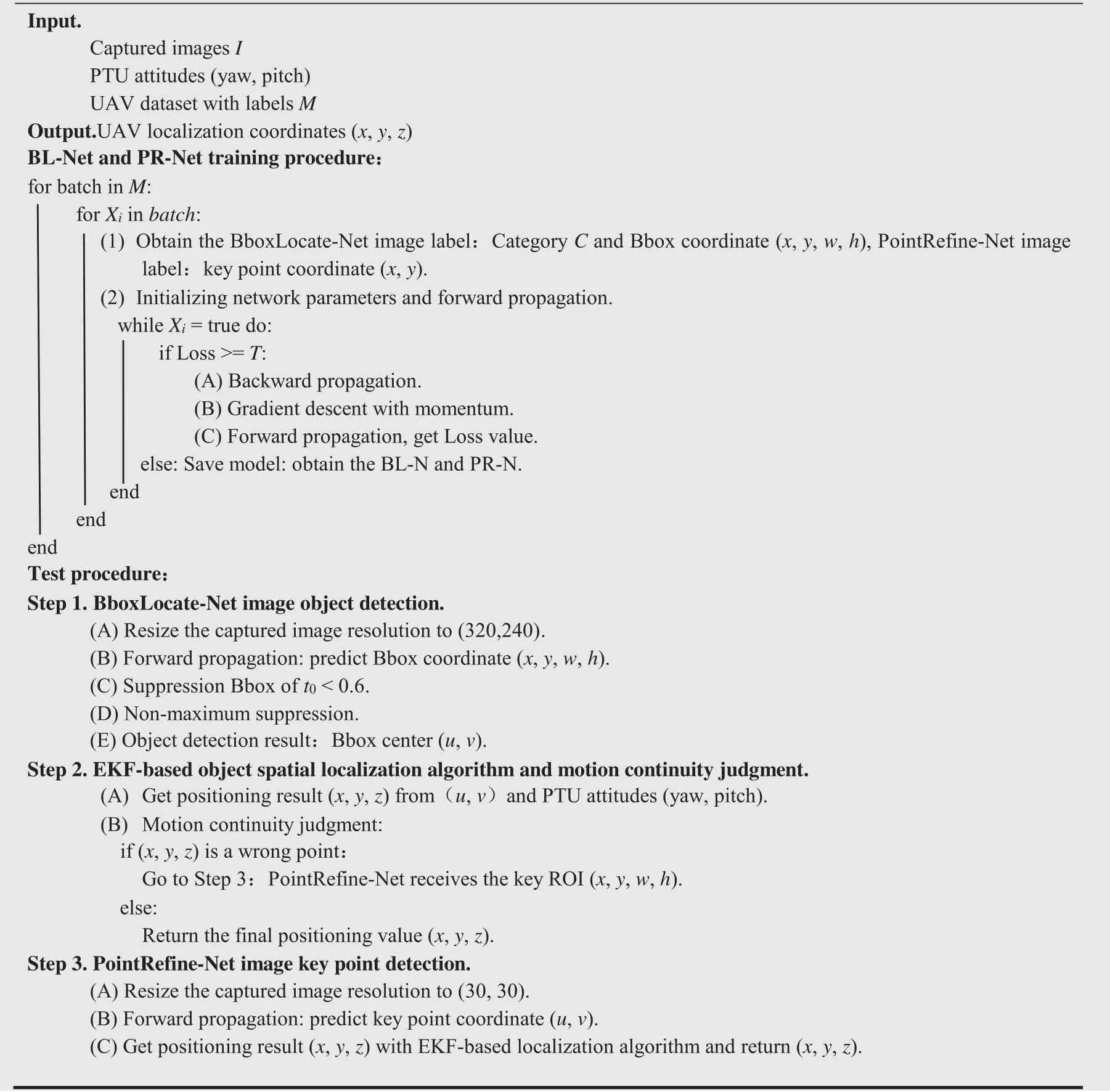
Table 1 UAV target localization method based on cascaded deep learning models.
(1) The first experiment verifies the accuracy and real-time performance of BboxLocate-Net by comparing it with several classical deep learning target detection algorithms.
And she told him that looking out of her little window she had seen her brothers flying over the wood in the shape of swans, and she showed him the feathers which they had let fall in the yard, and which she had collected
(2) The second experiment analyses the detection accuracy of PointRefine-Net and BboxLocate-Net, and proves that the second level network has certain optimization ability for the results detected by first level network.
4.1. Dataset and evaluation protocol
Our previous research has successfully carried out several experiments under normal weather conditions.3,10,13To meet the requirements on learning samples,we present an upgraded version of our self-constructed dataset which includes images from our previous dataset and new extracted images captured by the simulation platform.The collection of dataset is divided into two parts:real-scenario image acquisition and simulationscenario image acquisition.In the past work,a large number of UAV sequential landing images have been captured in the real flight experiments, and several volunteers annotated the sequential images to complete the construction of the realscenario dataset. The simulation images are mainly collected in the simulation system,namely Airsim,in which we can simulate the whole process of UAV landing on the runway, and can simulate a variety of backgrounds,such as the sky,mountains, forests and so on. Different time conditions such as morning, evening, noon and dusk, and different weather conditions including sunny, rain and snow can be set under the backgrounds.In the PX4 hardware-in-the-loop simulation system, since the 3D model of UAV is known, we can achieve automatic target labeling by coordinate system transformation. Our new dataset not only contained a larger number of images but also was gathered in more challenging weather conditions(stronger wind smog and heavy snow).The UAV position can also be set up in the distance and attitudes to expand the diversity of data samples. The dataset used in the experiment is an integration of simulated and actual datasets, of which the mixed training dataset consists of actual training dataset and simulated dataset, totaling 13,350 pictures. And the mixed validation dataset includes the actual validation dataset and the simulation validation dataset, with a total of 1500 pictures.For real-scenario flight application,we only test our algorithm on the actual flight dataset.
In this section,four evaluation indexes are adopted to evaluate the performance of the cascaded deep learning networks.We use mean Average Precision(mAP)and frames per second(fps) to evaluate the proposed BboxLocate-Net model. And the performance of PointRefine-Net is measured with the average detection error-‘‘Mean Error”and the failure rate of each key point - ‘‘False Rate”.
The above mentioned two evaluation indexes mAP and FPS both have clear meanings in the target detection field.We will not define them here. The Mean Error defined in this paper is measured by

where (u, v) and (^u,^v) are the ground truth and the detected position, respectively; BBox.wis the width of the bounding box detected by BboxLocate-Net.
In order to evaluate the accuracy of network prediction results, we define another indicator: False Rate. For the key point detection result of each frame, if the error is larger than 5%,it is considered the detection result of this frame as a failure.This means that the key point position error in each direction cannot be greater than 5% of the target area. In a group of experiments, the key point detection accuracy is defined as the ratio of the number of key points detected failure to the total number of key points.
4.2. BboxLocate-Net and PointRefine-Net training strategy
In this study,we train BboxLocate-Net network based on open source framework Darknet and PointRefine-Net on Caffe.The testing facility is a PC device with 64 GB internal memory and Ubuntu 14.04 operating system,i7-5930 K CPU and NVIDIA GeForce GTX 1080ti GPU.
In the training process of BboxLocate-Net,we used a batch size of 64, a momentum of 0.9, and a decay of 0.0005. BN(Batch Normalization) is used to regularize each time the weights are updated. Convolution-layer and pooling operations are used to extract features and generate tensors with specified size. In each forward prediction, the loss function is calculated in the detection layer, and the convolution kernel parameters are updated with the purpose of minimizing the loss value by the backward gradient descent algorithm.
The initialization of PointRefine-Net parameters is the same as that of BboxLocate-Net. Its input image resolution is 30×30, and the batch size is set to 32. We also use small batch random gradient descent to optimize network parameters.The network trains about 150000 times in total,and stops training when the loss value was less than 0.002.
4.3. BboxLocate-Net model based detection experiments
High-precision target detection is the basis of high-precision positioning for stereo vision system. At the same time, the real-time performance of the detection algorithm is also the key factor for the system to be practical.
To make a fair comparison between BboxLocate-Net and other algorithms in real time and accuracy, we have trained all kinds of deep learning methods20,28-30under the same conditions. Table 2 summarizes the training parameters that we used for training the UAV detection model. The training details of the network are as follows.
Using mixed landing dataset, we compared the proposed BboxLocate-Net detection results with that obtained by state-of-the-art CNN object detectors such as MobileNets-SSD29,30, YOLOv2-Tiny28, YOLOv320and MobileNets-YOLO20,29. We use mAP and FPS as comparison indicators for these algorithms. The performance comparison of our algorithm and the existing state-of-the-art approaches is shown in Table 3. Our approach is significantly better than MobileNets-SSD and YOLOv2-Tiny approaches.On the other hand, our tiny network, BboxLocate-Net, achieves an AP of 0.963 and FPS of 503. It outperforms most other algorithms,and is more efficient in terms of model size and computation complexity (GFLOPs). Fig. 5 shows the partial detection results of different CNN detection algorithms.
4.4. PointRefine-Net model based detection experiments
For the performance analysis of PointRefine-Net network, we take Mean Error and False Rate as evaluation indexes. In order to test the key point positioning effect in the algorithm,we synthetically analyzed the positioning results of six UAV key points and compared the detection results before and after PointRefine-Net. Fig. 6 shows the comparison of the Mean Error and False Rate between PointRefine-Net and BboxLocate-Net when detecting six key points. Compared with BboxLocate-Net, the detection results of PointRefine-Net have improved the accuracy to some extent and can be used as a correcting network for error points. Fig. 7 shows the comparison of several detection results before and after PointRefine-Net correction.
5. Real-scenario flight localization experiments
To comprehensively verify the performance of the algorithm in real-scenario flight,we designed the following two sets of flight experiments using the cascaded deep learning detection algorithm proposed in this paper and the EKF-based localization algorithm3as the solving algorithm.
(1) Based on Chan-Vese algorithm, GOTURN algorithm and BboxLocate-Net algorithm, the first group is used to calculate the UAV space trajectory, and to compare the accuracy and real-time capacity.
(2) To prove the better accuracy and robustness of the system after the PointRefine-Net coordinate correction algorithm, the second group mainly compares the influ-ence of PointRefine-Net coordinate correction algorithm and BboxLocate-Net algorithm on the accuracy and robustness capacity.

Table 2 Training parameters of five deep learning algorithms.

Table 3 Comparison of mAP value and FPS at IoU=0.5 of different CNN detectors.

Fig. 5 Test results of different CNN algorithms.

Fig. 6 Comparison of detection results at 6 key points before and after coordinate correction.
5.1. Real-scenario flight localization experiments setup
The real-scenario flight localization experiments are based on the ground-based visual system mentioned above.The runway baseline is about 10.77 m. The high-precision PTU is set on both sides of the runway and a visible light camera is fixed on the PTU. Each of PTU has two degrees of freedom to expand the search field. At the same time, the high position resolution (0.00625°) and high rotation speed (50 (°)/s) make the positioning more accurate.

Fig. 7 Comparison of key point detection results before and after coordinates correction.
Specifically, for visible light camera, we selected the imaging source color CCD high-speed industrial camera, model DFK 23G618, which uses a CCD chip of SonyICX445AQA with a pixel resolution of 640×480, a cell size of 3.2 mm.The lens of the vision system that we adopted is 60 mm.According to the pin-hole camera model,the size of the detection window is 42.67 m×32 m when the depth distance is 800 m. For the medium-sized UAV used in the experiment,the wingspan of the UAV is 2.2 m,and its theoretical imaging pixel at 800 m is 32.99 pixels which can be effectively identified by our CNN model at this distance. The minimum target that our cascaded CNN algorithm can detect is 15 pixels, at which point the corresponding theoretical location distance can be calculated as 1762.5 m. However, because the height of UAV is only about 1/4 of its width, and there is water mist interference and light path consumption in actual use, an experiential guiding distance is set as 800 m. The autolanding experiments are conducted in accordance with such specifications as well.
Toextendthefieldofview,weadoptedprecisionPTUtoactuate the camera,which is a two-axis gyro stable turntable from FLIR CorporationoftheUnitedStates,PTU-D300.Theturntablesends commandsthroughaRS232serialport,andfeedbacksitsownstatus online,including the turntable azimuth(pan)and pitch(tilt)angles.Itsangleresolutionis0.006°.PTU-D300isdrivenbyasteppingmotorandcanmeettherequirementsofclosed-looptracking targets.The PTU has better vibration and impact resistance,and protectionlevelofIP67.WhentheUAVflightspeedis30 m/sand thedistancefromtheguidancesystemis200 m,therequiredrotation speed of the turntable is 4.3(°)/s,which is within the normal workingrangeofthePTU.Weinstalledthecameraonthetopbracketing,and the assembled individual vision system is illustrated in Fig.1.
Finally,the target detection method mentioned in the paper is used to process the images collected by the two cameras,and then the positioning results are compared with the previous work.
5.2. BboxLocate-Net model based localization experiments
(1) Experiment 1.1: Accuracy experiments without PointRefine-Net
Fig.8 shows autonomous landing trajectories and localization errors in x,y and z directions.One trajectory is calculated by EKF-based localization algorithm. The blue trajectory is generated by DGPS as a reference trajectory, and the yellow,light blue and red ones are generated by Chan-Vese,GOTURN and BboxLocate-Net algorithms, respectively.3,13The blue area, green area and yellow area in Fig. 9 represent three stages of approaching, descending and taxiing in the landing process.
The Root-Mean-Square Error (RMSE) in each axis using EKF is presented in the right of Fig. 9. ex, eyand ezdenote RMSE in x, y and z directions respectively. For the convenience of display, the error is displayed after taking ln(1+e). The error distribution curves for each axis calculated by EKF at different distances are shown in Fig. 10.
In Fig. 10, when the y coordinate is less than 187 m, the deviation increases rapidly.This is due to the weak DGPS signal when the aircraft approaches the ground.
By analyzing the two figures together, it is clear that the y axis direction error in the three stages is much greater than that in the x axis and z axis directions.This is due to the error characteristics of binocular vision.Since the y axis is parallel to the runway and the runway is long enough,a large y axis direction error does not affect the UAV landing process. Relative to y axis direction error, x and z axis direction error are critical for safe landing. Excessive x axis direction error may cause the UAV to deviate from the runway, while too large z axis direction deviation will cause the UAV to miss the landing point, which is prone to safety accidents. It can be seen in Fig. 9 that the error of the x axis and z axis landing is within 0.3 m in both the stage of approaching and the stage of descending.Only in the taxiing stage,the x axis direction error will reach a larger value,which is caused by the binocular calculation characteristics and the image target positioning error.Since the UAV has landed during the taxiing stage, a larger positioning error is acceptable.
According to Fig.9,the BboxLocate-Net localization algorithm reduces the deviation to some extent at all three axes,especially in the‘‘Air&Ground”stage,the trajectory generated by BboxLocate-Net has a smaller deviation than that of Chan-Vese and GOTURN algorithm. To sum up, the localization accuracy improvement owing to BboxLocate-Net localization algorithm is practically significant for UAV autonomous landing.
(2) Experiment 1.2: Real-time capability experiments without PointRefine-Net
The real-time performance of the algorithm has always been a key and common problem in practical engineering applications, and it is also our focus.
We compare the frames per second(fps)of object detection with different algorithms, and these algorithms are tested in the same equipment, which is a PC with i7-5930 K CPU and 64 GB internal storage. The results are shown in Table 4.The detection speed of BboxLocate-Net can reach 500 fps,about 500 times of Chan-Vese algorithm and 3 times of GOTURN algorithm. Compared with Chan-Vese algorithm and GOTURN algorithm, our method has great progress in real-time capability.
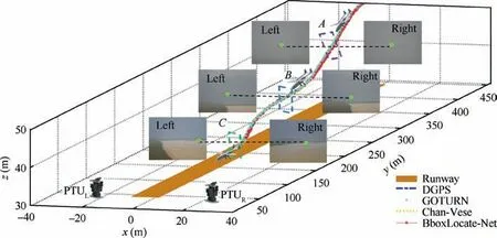
Fig. 8 Localization results using different UAV detection algorithms.

Fig. 9 Accuracy comparison of spatial positioning results.
5.3. Cascaded deep learning model based localization experiments
(1) Experiment 2.1:Robustness capability experiments with PointRefine-Net
Another trajectory is shown in Fig.11.The image detection results at point D and F with large deviation in Fig. 11 are shown in Figs. 12(a) and (b). It shows that the location error is mainly caused by the wrong image detection results.We conduct PointRefine-Net operation at points D and F. The light blue dot and yellow dot are the results before and after correction,respectively.And the light blue trajectory and yellow trajectory in Fig. 12 respectively represent the positioning results before and after correction. We can see that PointRefine-Net shows better robustness than BboxLocate-Net algorithm.
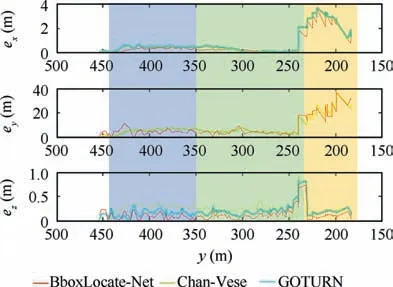
Fig. 10 Localization errors in x, y and z directions for different distance conditions.

Table 4 Processing rate with three different detection methods.
In Fig. 11, the S area represents the case that part of the UAV goes out of the field of view.The detection results of four typical frames in S area are shown in Fig.13.G,H,I and J represent four typical frames which are out of the FOV in S area.Purple points are the detection results of Chan-Vese,red points indicate the detection results of GOTURN,and light blue and yellow points indicate the detection results before and after PointRefine-Net network respectively. When the target image coordinates out of the FOV, the comparison of detection results also shows that PointRefine-Net has a more robust performance.
The reason why part of the wing is out of view is that the control accuracy of PTU is unsatisfactory. For analyzing the effect of PTU control accuracy error on spatial positioning,a Monte-Carlo method is used for quantitative evaluation on the effect of PTU control accuracy error on spatial positioning. Eventually, specified artificial servo errors are assumed added to the obtained PTU angles. We analyzed the positioning accuracy after incorporating 1 mrad and 2 mrad error perturbations into the left PTU true values, respectively. When 1 mrad error perturbation is added,the errors in x,y and z direction at several specific distances are shown in Table 5. If 2 mrad error perturbation is added to the left PTU, x, y and z direction errors are shown in Table 6. The analysis results show that there is a large deviation between measurements and the GPS true values in the y distance and z distance when 2 mrad error is added. When the y distance is only 150 m, the height and distance errors are still 0.6 m and 3.176 m respectively, which makes it difficult to guarantee the accurate UAV guidance.
(2) Experiment 2.2: Accuracy experiments with PointRefine-Net
The light blue and yellow trajectories in Fig. 11 are generated by different detection algorithms but same localization algorithms. Same as above, blue is generated by DGPS, and light blue and yellow are generated by BboxLocate-Net (BLN) and PointRefine-Net (PR-N) algorithm, respectively.Table 7 shows the comparison of RMSE with EKF at each axis between the two algorithms in actual landing experiments.It can be seen that the algorithm after PointRefine-Net has higher location accuracy.
We also analyze the spatial positioning accuracy errors caused by detection pixel errors.Fig.14 shows the spatial positioning error changes in each coordinate direction caused by target detection errors(0-30 pixels)in U direction and V direction of image. We set up three cases of pixel deviation. As shown in Fig. 14, the red point indicates that the pixel error increases in the same value in the U and V directions, the yellow point indicates that the pixel error is constant in the V direction and changes in the U direction, and the cyan point indicates that the error is constant in the U direction and changes in the V direction. It is obvious that with the increase of detection error, the Y direction error increases the fastest.This is because the baseline of the binocular vision system is much smaller than the distance from the binocular vision system during the UAV landing.
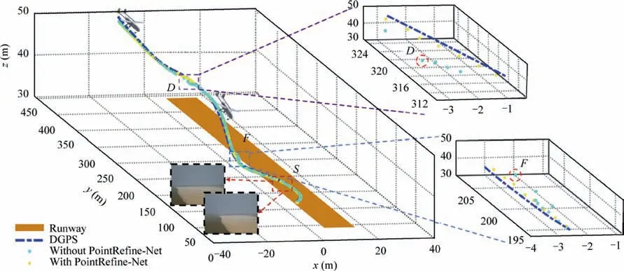
Fig. 11 Comparison of localization results before and after PointRefine-Net.
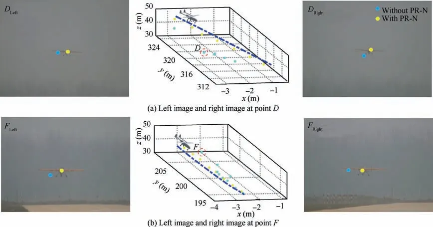
Fig. 12 Comparison of key point detection results before and after PointRefine-Net (PR-N) coordinate correction.

Fig. 13 Key point detection results detected by four detection algorithms.
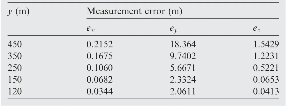
Table 5 Analysis of positioning error under different y distance (1 mrad error perturbation).
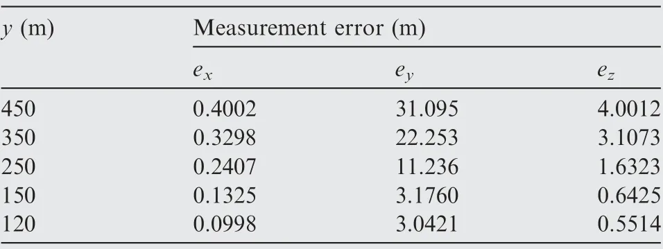
Table 6 Analysis of positioning error under different y distance (2 mrad error perturbation).
(3) Experiment 2.3: Real-time capability experiments with PointRefine-Net
We use the flight trajectory mentioned in Experiment 2.1 to compare the localization speed before and after PointRefine-Net. The results are shown in Table 7. BboxLocate-Net algorithm has better real-time capability, but PointRefine-Net algorithm has higher location accuracy while the real-time capability is kept in the same level.
6. Concluding remarks
In this paper, a novel cascaded deep learning detection model has been proposed and developed for autonomous landing of unmanned fixed-wing aerial vehicles. A light-weight deep learning model enables a higher processing speed and makes the reasonable check and further optimization of UAV coordinates a reality. Flight experiment results validate that theapproach attaches ~500 fps and higher positioning accuracy than previous work. By making full use of the expansibility of the ground computing resources, we promote the visual guidance landing system to be practical.
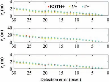
Fig. 14 Localization errors in x, y and z axis directions caused by different detection pixel errors.
In the subsequent work, the developed algorithm is potentially extended to enabling detection and localization based on multiple key areas and key points.This algorithm is also to be developed from vision-based position to pose (position-andattitude) during the autolanding. In details, multiple anchors are to be detected simultaneously to support pose estimation then.
Declaration of Competing Interest
The authors declare that they have no known competing financial interests or personal relationships that could have appeared to influence the work reported in this paper.
Acknowledgment
This study was supported by the National Natural Science Foundation of China (No. 61973327).
 CHINESE JOURNAL OF AERONAUTICS2021年5期
- CHINESE JOURNAL OF AERONAUTICS的其它文章
- Ferrofluid moving thin films for active flow control
- Preliminary study on heat flux measurement data of TT-0 flight test
- An analysis and enhanced proposal of atmospheric boundary layer wind modelling techniques for automation of air traffic management
- Jet sweeping angle control by fluidic oscillators with master-slave designs
- Hot deformation behavior and microstructure evolution of the laser solid formed TC4 titanium alloy
- Electrochemical trepanning with an auxiliary electrode
