Integrated method of guidance, control and morphing for hypersonic morphing vehicle in glide phase
Cunyu BAO, Peng WANG, Guojian TANG
College of Aerospace Science and Engineering, National University of Defense Technology, Changsha 410073, China
KEYWORDS Adaptive dynamic surface;Glide phase;Hypersonic morphing vehicle;Integrated guidance control and morphing method;Variable span
Abstract The morphing technology of hypersonic vehicle improved the flight performance by changing aerodynamic characteristics with shape deformations,but the design of guidance and control system with morphing laws remained to be explored. An Integrated of Guidance, Control and Morphing(IGCM)method for Hypersonic Morphing Vehicle(HMV)was developed in this paper.The IGCM method contributed to an effective solution of morphing characteristic to improve flight performance and reject the disturbance for guidance and control system caused by the morphing system for HMV in gliding phase.The IGCM models were established based on the motion models and aerodynamic models of the variable span vehicle. Then the IGCM method was designed by adaptive block dynamic surface back-stepping method with stability proof. The parallel controlled simulations’ results showed the effectiveness in accomplishing the flight mission of IGCM method in glide phase with smaller terminal errors.The velocity loss of HMV was reduced by 32.8%which inferred less flight time and larger terminal flight velocity than invariable span vehicle. Under the condition of large deviations of aerodynamic parameters and atmospheric density, the robustness of IGCM method with variable span was verified.
1. Introduction
The past decade has seen the rapid development of hypersonic vehicles for the more notable features of long flight range,strong maneuver and strong penetration by hypersonic gliding in the upper atmosphere by comparing with traditional aircrafts and ballistic vehicles.1However, the aerodynamic loads changed rapidly and presented great uncertainties under the hypersonic flight. For instance, the aerodynamic performance of hypersonic waverider vehicle deteriorated significantly when the actual flight state drifted away from the preset state.2The improvement of hypersonic aerodynamic performance would be the crux of hypersonic vehicle design.3Besides, the hypersonic vehicle bore the severe aerodynamic heating problems and the boundary of flight corridor was restricted strictly of heat flux density.4
Fortunately, the morphing technology of vehicles independently changed the shape and structure according to flight commands so as to improve aerodynamic performance and heat flux density.5The shape parameters were regarded as controllable variable to change the aerodynamic characteristics actively. So it would adapt to a wider range of flight airspace and velocity domain. The lift-drag ratio of morphing vehicle was able to remain in maximum to reduce the energy loss and dynamic pressure.So the morphing vehicle need less initial velocity to complete the gliding flight. The less initial velocity,larger flight range, higher attack kinetic energy and the wider boundary of flight corridor would be obtained in gliding phase with morphing technology.6
By applying the morphing technology to hypersonic vehicle, the Hypersonic Morphing Vehicle (HMV) was designed.The both unique advantages of hypersonic gliding and morphing technology were integrated on HMV.7Besides,the morphing technology eliminated the aerodynamic influence caused by the flight state deviation of hypersonic vehicle.8Therefore,the morphing technology will provide innovative insights into the field of hypersonic vehicle in recent years.
However, the hypersonic flight and morphing technology triggered high-impacts on the guidance and attitude control systems of HMV.9The aerodynamic and dynamic models of hypersonic vehicle showed great non-linearity, fast timevariant and strong coupling because of the high velocity.10,11Moreover, the morphing technology changed the physical and geometric parameters of the vehicle which meant extra complexity of flight control system.12Another crucial issue was how to play a potential role of morphing strategy to cooperative hypersonic gliding flight.13,14So there remained a need in the field of hypersonic vehicle and morphing vehicle for new methodology to design the guidance and control system for HMV.
A number of techniques have been proposed in the recent literature in the domain of guidance and attitude control systems of hypersonic vehicle. He et al. developed a fast generation method of multi-target entry trajectory under uncertain conditions15for hypersonic vehicle. The Gaussian pseudo spectral method for trajectory generation under thermal load experiment have been reported by Zhang et al.16However,the morphing laws of HMV remained unknown in gliding phase, traditional guidance method by trajectory generation methods was not suitable for HMV. For attitude control of hypersonic vehicle, Cheng et al. proposed a quasi-continuous high-order sliding mode control approach for the longitudinal model of a generic hypersonic flight vehicle.17Another method for addressing this issue was described by Cheng et al. They tested a disturbance rejection control method with actuator dynamics respectively for air-breathing hypersonic vehicle.18Despite the success of above work in guidance and attitude control systems,they still suffered from the stability and accuracy problems caused by the separate decoupling design philosophy of guidance and attitude control systems.19,20The coupling information between guidance loop, attitude control loop and a lot of uncertainties under hypersonic flight was too significant to be ignored.21Recent developments for the problems have led to an interest in Integrated Guidance and Control (IGC)method which made full use of the coupling information to improve the performance of the flight system.22The IGC methods has inspired a lot of about the guidance and control design of HMV, e.g. Wang et al. have examined the effects of the IGC with impact angle limitation to realize active disturbance rejection and a low-order IGC for hypersonic vehicle.23
In most studies of morphing vehicle, attitude control has been emphasized with attention being given to the physical and geometric characteristics mutations caused by morphing technology. The aero-structural optimizations were implemented to find the aerodynamic advantage of morphing technology compared to conventional aircraft.24In aspect of the dynamic of morphing vehicle, recent studies indicated that piezoelectric sensors realized the wing deformation sensing expectedly for morphing technology.25Yue et al. studied the Z-wing morphing vehicle and demonstrated that the aerodynamic change dominated the serious impacts on the dynamic performance in the morphing process.26In the morphing cooperative control of low velocity morphing vehicle, a track controller underlying active morphing technology was validated by applying the non-linear dynamic inversion method with morphing technology.27Chen et al. indicated that a complex trajectory could take advantage of morphing rules in keeping good aerodynamic performance with more efficient than trajectory optimization for morphing aircraft.28Gong et al. treated morphing as a function of the system states for enhancement of flight performance and tested a switching type controller composed of the type controller composed of the outer part and inner part by the Q-learning algorithm.29Yin et al. utilized the fuzzy robust control strategy to stabilize the morphing technology cooperative flight of the morphing vehicle in the maneuvering flight by adding the deformation to the control inputs to achieve the flight target.30However,most of the research in the morphing vehicles was focused on low velocity aircraft.
In the respect of HMV,the type-2 TSK fuzzy sliding mode control strategy was applied to an adaptive mode switching method by Jiao et al.31For Hypersonic Morphing Aircraft(HMA), the HMA’s modes with retracted winglets was based on X-24B configuration.The adaptive mode switching method was effective for the longitudinal dynamics model but there was no consideration of the lateral phase.Peng et al.optimized the glide trajectory based on multi-objective optimization method and presented the importance of morphing technology on the glide trajectory for the hypersonic morphing vehicles with different morphing modes.32The morphing vehicle flied further with a smaller total heat of the sweep of the wing than non-morphing vehicle. However, it aimed at the trajectory optimization and was lack of guidance and control. Bao et al. proposed an IGC scheme for hypersonic morphing missile in dive phase by the adaptive dynamic surface backstepping method. The IGC method with angle constraint was analyzed and the optimization of the flight control system with morphing shape was proved.33But the IGC scheme was designed for dive phase which was not suitable for gliding flight. A switched adaptive active disturbance rejection controller was implemented to variable structure near space vehicles based on adaptive dynamic programming by Dong et al.34The variable gain control strategy presented high flight performance and effectiveness for morphing sweep vehicles.
Collectively, most of the above researches have more concentrated on the guidance and attitude control systems design for hypersonic vehicle and the controller design for low velocity morphing vehicles.However,many of methods currently in use for HMV may lack of reliability and validity. There was little discussion about making the morphing technology cooperate with the guidance and attitude control system for HMV in glide phase. This study aimed to address the following problems:
(1)How to treating morphing as control input to cooperate the guidance and attitude control system and obtain a better flight performance in gliding phase?
(2) How to design an effective IGCM method for HMV to reject the disturbance of the guidance system, attitude control system caused by the morphing system?
The aim of this research project has therefore been to try and establish an Integrated Guidance, Control and Morphing(IGCM) method for a HMV by treating morphing as control input in the glide phase. The IGCM method roadmap represented visually by Fig. 1 below was proposed to address the above two problems. The outer loop was the guidance loop for trajectory control while the inner loop was the control loop for attitude and morphing control to track the guidance commands. The IGCM method in the whole glide phase was integrated designed by adapting the adaptive dynamic surface back-stepping control method. The IGCM method was the first study to undertake the morphing technology and the coupling of guidance with attitude control system in an effort to IGCM design of HMV in gliding phase.Under variable Mach numbers in gliding flight, the vehicle changed the shape to maintain the minimum resistance with satisfying the guidance commands so as to reduce the velocity loss and achieve greater flight range and attack kinetic energy.
The overall structure of the paper took the form of six sections, including this introductory section. The second section began by laying out the HMV modes and the motion models with variable span were presented. In the third section, the IGCM method was designed in glide phase by adaptive dynamic surface back-stepping method. The fourth section showed the test results of IGCM method focusing on the analysis of effectiveness and robustness. Some issues were discussed in fifth section. Finally, the conclusion section gave a brief summary and critique of the findings.
2. Motion models of HMV
2.1. Shape and parameters of HMV
The research object under discussion was within the scope of HMV with variable spans. The outline was showed in and morphing modes was showed in Fig. 2.33
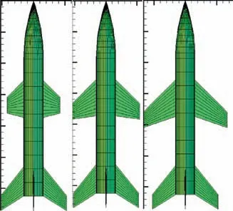
Fig. 2 Outline and morphing modes of HMV.
As showed in Fig. 3, the HMV consisted of three parts, a rotational symmetrical slender body, two variable span wings and four invariant tails.From left to right in Fig.3,the wings’span changed from minimum to maximum. The variable span of the wing was synchronously varied on both sides of the wings without differential varying. The definitions and values of parameters labeled in Fig. 3 were showed in Table 1. The morphing rate ξ of the variable span was defined as33

2.2. HMV dynamics models
2.2.1. Centroid dynamic models
To establish the centroid dynamics models for HMV, the factors of the earth’s rotation and the earth ellipsoid must be considered because the flight range and time were quiet long in glide phase. Then the centroid dynamics models were established in the ballistic coordinate system with spin ellipsoid earth model as
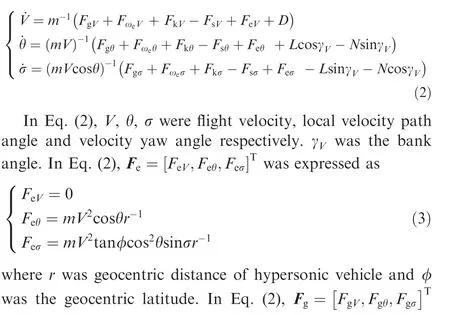

Fig. 1 Roadmap of the IGCM method for HMV.
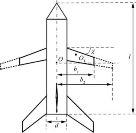
Fig. 3 Shape parameters of HMV.
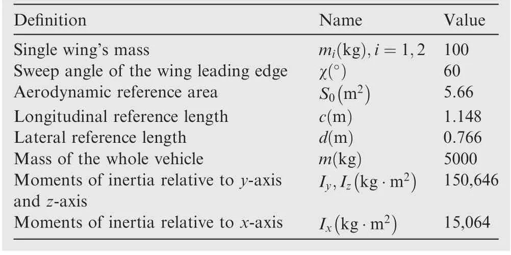
Table 1 Definitions and values of vehicle characteristic parameters.
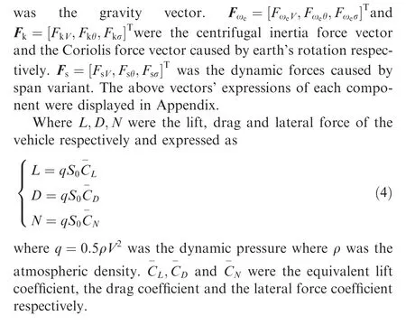
2.2.2. Rotational dynamic model
The rotational dynamic models of the variable span vehicle were

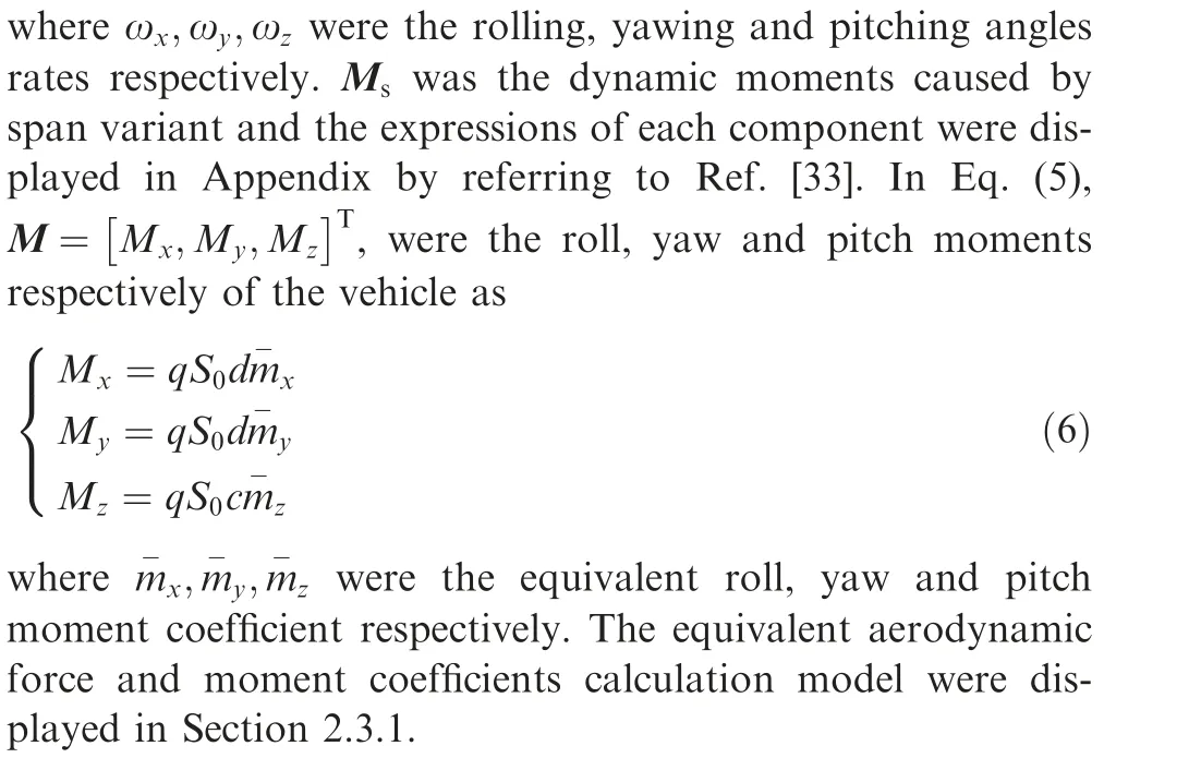
2.3. Aerodynamic models and aerodynamic analysis of HMV 2.3.1. Aerodynamic models of HMV
Currently, there were little public aerodynamic data on HMVs. Therefore, the aerodynamic data including lift coefficient CL, drag coefficient CD, lateral coefficient CN, roll moment coefficient mx, yaw moment coefficient myand pitch moment coefficient mzwere calculated by using aerodynamic software under each parameter point combination of different span morphing rate ξ, Mach Ma, attack angle α, sideslip angle β, roll fin deflection δx, yaw fin deflection δyand pitch fin deflection δz.
The reference area S0were varying during the morphing process of vehicle. For the convenience of subsequent calculation, the reference area S0was dealt as a constant. The effects of the reference area variation caused by morphing was classified into the equivalent aerodynamic coefficient as

The influence of deformation rate on the reference area was directly normalized to the aerodynamic coefficient. In this case, the reference area was a constant, whose value was the reference area without deformation. Through the treatment, the influence of deformation rate on aerodynamic loads was only reflected in the aerodynamic coefficient which brings great convenience for the subsequent control laws design.
Then, the expression of the aerodynamic coefficients was obtained by polynomial fitting as
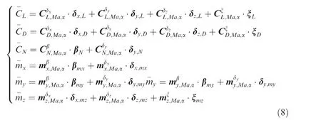
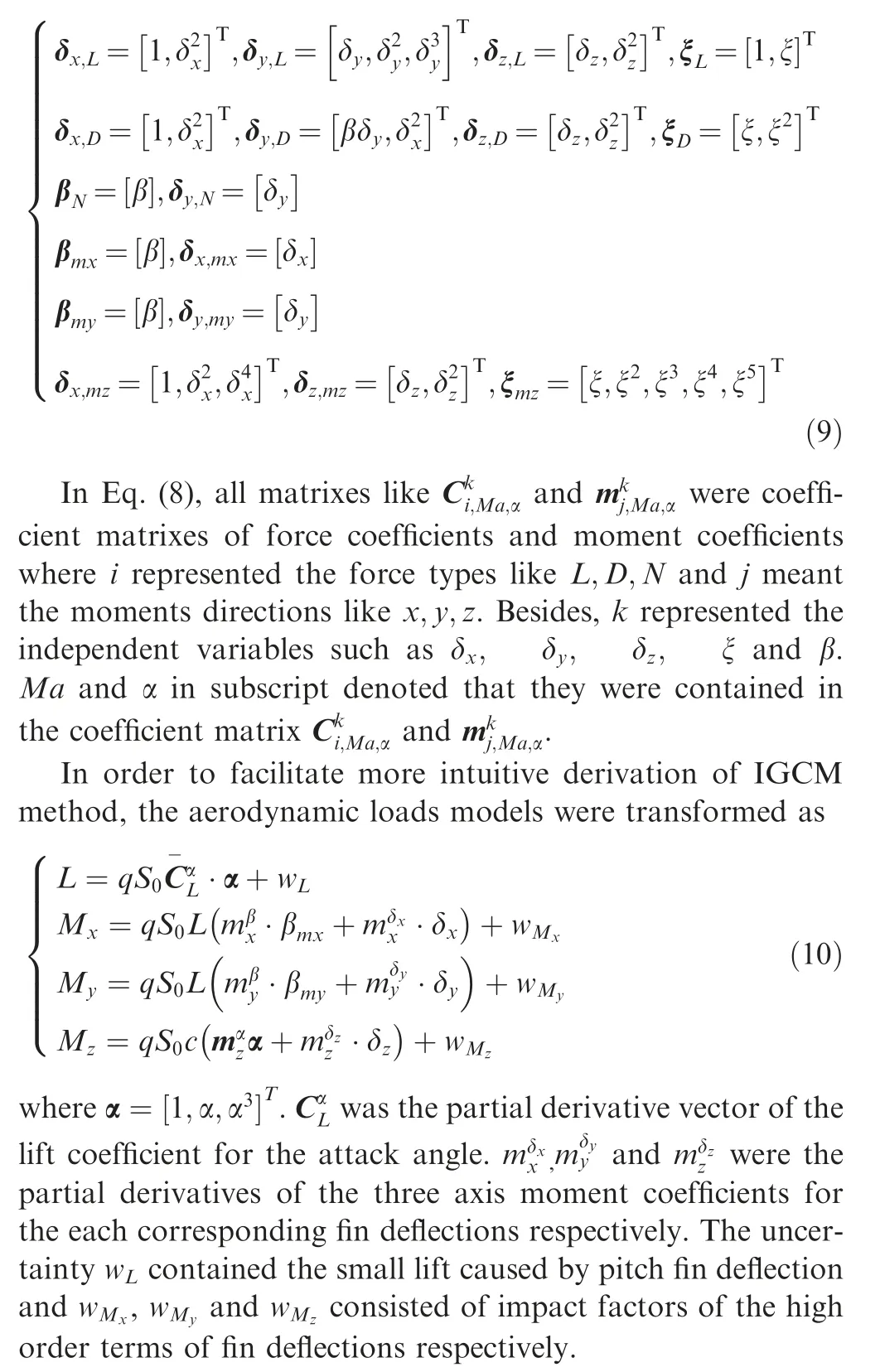
where all vectors like β,δ and ξ were variable vectors of sliding angle, fin deflections and morphing rate. Each variable vector was composed of the following specific expressions as
2.3.2. Aerodynamic analysis of HMV
Compared with the invariant vehicles, the morphing process significant impacted on the aerodynamic characteristics of the vehicle. It was essential to investigate the specific influence laws of the morphing on the aerodynamic characteristics. As can be seen from the aerodynamic models in Eq.(8),the morphing rate mainly affected the longitudinal aerodynamic coefficients including CL, CDand mzbecause the spans of HMV were symmetrically varied on both sides. The longitudinal aerodynamic force and moment coefficients under different morphing and Mach numbers conditions were calculated through the aerodynamic model in Eq. (8). In the case of α=5°and β=δx=δy=δz=0, the longitudinal aerodynamic coefficients consisted of CL, CDand mzwere calculated when the values range of Mach and morphing rate was

The graphs displayed in Figs. 4 to 5 below described the trends of the Calculation results.
The influence laws of the morphing on the longitudinal aerodynamic coefficients were briefly summarized in Table 2 according to the variation results. In Table 2, ↓denoted increase while ↑denoted decrease.
It was revealed that the drag coefficient was negatively correlated with Mach from the Figs.4(a)to 5(a).Under the same Mach number, drag coefficient increased with the increase of morphing rate. The similar trends was observed in Figs. 4(b) to 5 (b) of lift coefficient. In contrast, the Figs. 4 (c) to 5(c)showed the pitching moment coefficient was positively correlated with Mach number. Under same Mach number,pitching moment coefficient decreased with the increase of morphing rate.According to the Figs.4(d)to 5(d),in the case of the fixed morphing rate, the lift-drag ratio increased first and then decreased with the increase of Mach number. There was an optimal Mach Maoptfor the lift-drag ratio.At the same Mach number,the variation of lift-drag ratio with the different morphing rate was much complex as follow:
If Ma <6, then the lift-drag ratio increased with the morphing rate increasing;
If 6 <Ma <12, then the lift-drag ratio decreased first and then increased;
Otherwise if Ma >12,then the lift-drag ratio increased first and then decreased.
The effects of morphing rate and Mach on aerodynamic characteristics reported above illustrated that the drag coefficient of vehicle could be minimum or the lift-drag rate could be maximum by adjusting the morphing wings’ span. Moreover, the adjustment strategies of morphing rate was significant different under different Mach numbers because the complex effects of lift-drag rate showed in Fig.5(d).The aerodynamic analysis under discussion was within the scope of the similar outline structure and flight condition as the HMV in Fig. 2.
3. IGCM method in glide phase
3.1. IGCM models in glide phase
On the basic of the motion models in Section 2, the IGCM model was established and composed of the centroid dynamic equations, the rotational kinematic equations and the rotational dynamic equations.There was a need to transform these equations into control oriented I/O models with strict feedback forms.
3.1.1. Control oriented centroid dynamic equations
The centroid dynamic equations in Eq. (2)of the HMV established in the ballistic coordinate system was transformed into control oriented I/O models with strict feedback form as

where

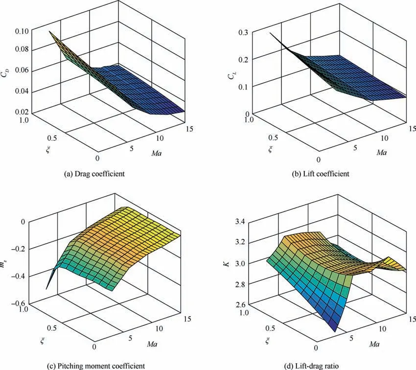
Fig. 4 Variations of aerodynamic coefficients with varying of morphing rate and Mach number.
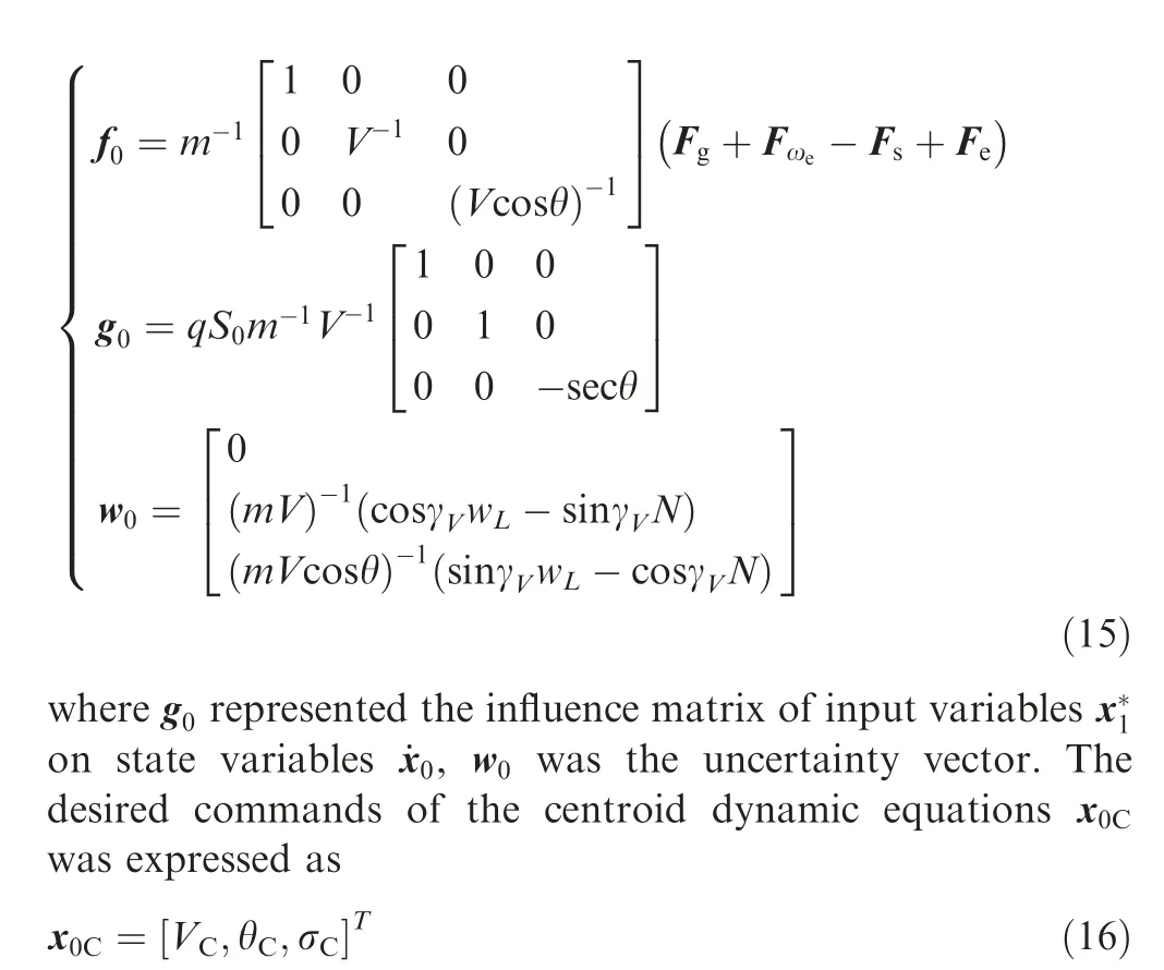
The three components of the x0Cwas determined by the minimum velocity loss,the control of longitudinal and the control of lateral azimuth error flight paths respectively. The unpowered flight of a HMV to a preset target area was a basic task of guidance system. To complete the gliding mission with high accuracy, terminal constraints including terminal positions and velocity was denoted as

where φt,ψt,Ht,Vtwere terminal latitude, longitude, altitude and velocity of the HMV and φT,ψT,HT,VTare preset latitude,longitude, altitude and velocity of target. The longitudinal flight plane was controlled by deriving the expression of the desired velocity path angle. The centroid motion equation was expressed as

where ψ was the longitude.For longitudinal plane motion,the flight distance Srof the vehicle was determined by

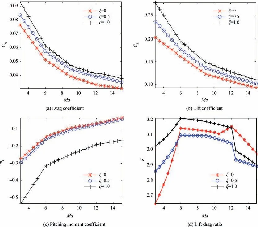
Fig. 5 Curves of aerodynamic coefficients with varying of Mach under different morphing rate.
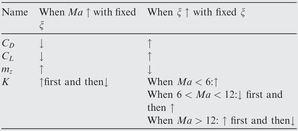
Table 2 Effects of morphing rate and Mach on longitudinal aerodynamic characteristics.
Substituting ˙r=Vsinθ into Eq. (19) yielded to get

Considering that the path angle of the gliding flight was approximately constant and the change was slow, the analytical formula of Srwas obtained by applying the Newton-Leibnitz formula as

where r was the current geocentric distance and rTwas the target point’s center distance. Under the premise of ignoring the height difference,the actual large distance between the starting point and the target was inducted by the principles of spherical geometry and denoted as

where φTand ψTwere the latitude and longitude of the target point. Then a desired local velocity path angle command was obtained by combine the Eqs.(21)and(22)to reach the preset target as

The lateral channel control was keeping the lateral azimuth error within an acceptable small amount to achieve the distribution of the aerodynamic lift. The lateral azimuth error was the difference of the velocity yaw angle σ and the azimuth sight angle σC. The expression of azimuth sight angle σCwas

Because the vehicle was unpowered and the falling height in the glide phase was small, it was difficult to control the flight velocity. The initial flight velocity was maximal in whole gliding phase and then the velocity decreased continuously.Fortunately, the morphing of HMV would change the drag coefficient so as to minimize the energy loss under the longitudinal and lateral commands.Thus the velocity command could be set as

3.1.2. Control oriented rotational kinematic equations
The rotational kinematic equations denoted by the attack angle α, sideslip angle β and bank angle γVwas
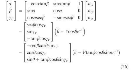
Then rotational kinematic equations were transformed into the control oriented I/O forms as

where
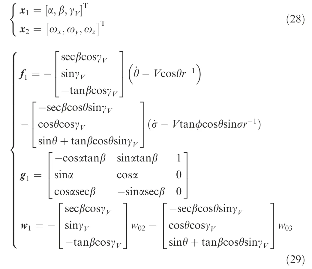
where g1represented the influence matrix of input variables x2on state variables ˙x1.w1was the uncertainty vector and the w02and w03was the second and third elements of w0.
3.1.3. The control oriented rotational dynamics equations
Compared with the rotation rate of the HMV,the earth’s rotation rate was quiet tiny. So the earth’s rotation could be ignored in rotational dynamics model. Substituting the Eq.(10) into the Eq. (5), the simplified rotational dynamics equations with the input of fin deflections was transformed as35

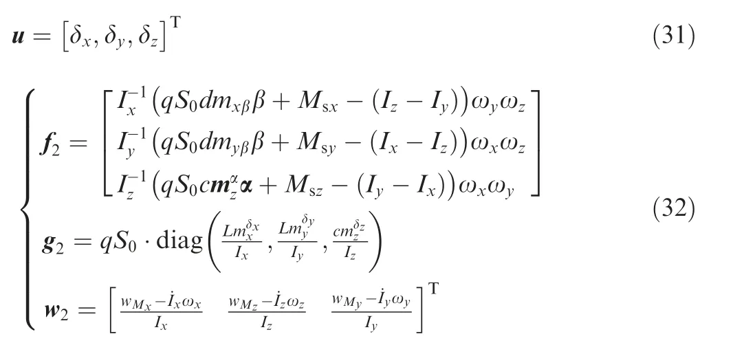
The change rates of each moments of inertia were treat as an uncertainty vector w2in Eq. (32).
In summary, an IGCM models consisted of Eq. (16), Eq.(13) Eq. (27) and Eq. (30) for HMV was obtained as

In Eq. (33), the uncertainty vectors w0, w1and w2were bounded as

where eiwere the unknown constants.
3.2. IGCM method in glide phase
The IGCM model of HMV in glide phase was Eq. (33). The adaptive dynamic surface back-stepping control method was used to establish the IGCM method for the flight control below.
3.2.1. Design of IGCM by adaptive dynamic surface backstepping method
To design an adaptive dynamic surface back-stepping control method, the Eq. (33) was required to non-singular as

Therefore, under certain assumptions as

then g1was non-singular in glide phase. Θ was the bounded closed set in R2.Then an IGCM method was established based on the adaptive dynamic surface back-stepping method below.35
Step 1. the first dynamic surface back-stepping was designed as

The change rate of the dynamic surface back-stepping s0based on the slide mode law was designed as

where sgn x( ) was the saturation function defined as

For the convenience of representation, Eq. (38) was transformed as follow form
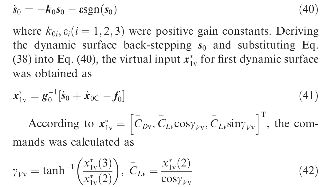
For the hypersonic vehicles,the gliding flight was restricted by the complex hard process constraints including heat flux density,overload and dynamic pressure what can be expressed as
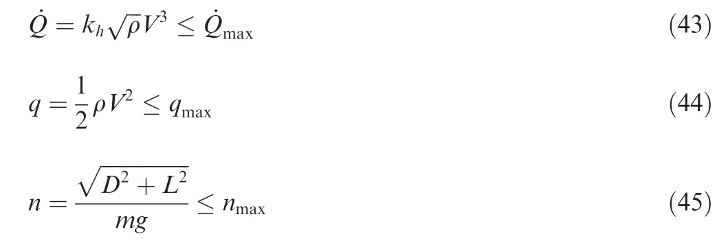

where LCwas the desired lift for centroid translational loop.Substituting the Eq. (46) into the Eqs. (43), (44) and (45)yielded
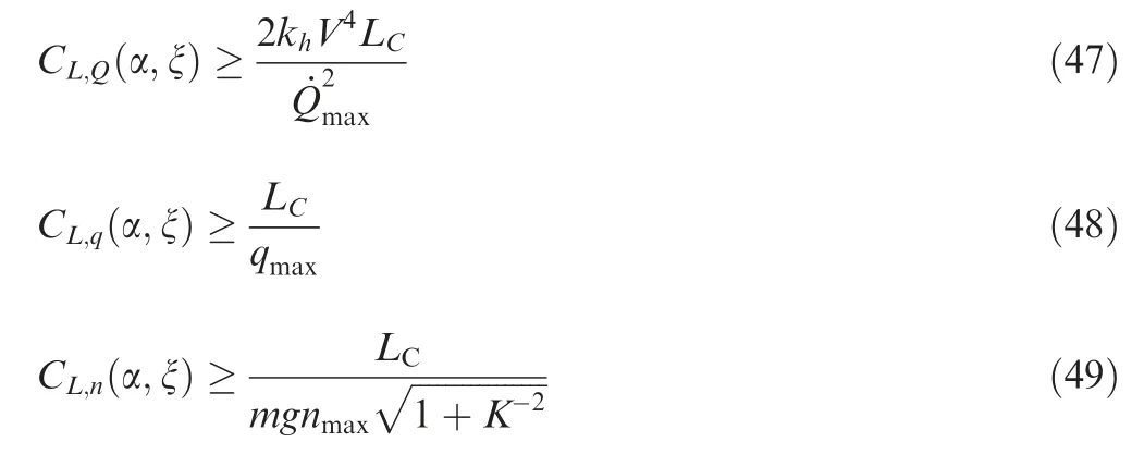
where K was the lift-drag ratio. Then the process constraints was transformed into the lift coefficient constraints which was under consideration in the optimization of(α,ξ ).Because the HMV was unpowered, the command of flight velocity could not be fully tracked. However, by adjusting the morphing span of HMV,the drag coefficientremained minimized to minimize the energy loss and the lift commandwas tracked. Then, the velocity V would approach the command VCas much as possible.Therefore,the virtual command of attack angle αvand morphing rate ξvwas optimized as
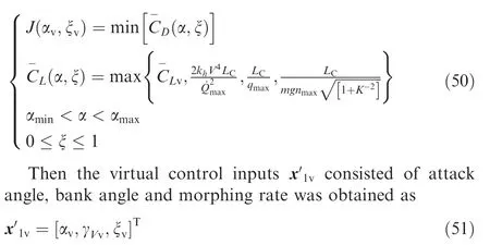
Considering that the Bank to Turn (BTT) mode was applied to HMV, the virtual command value of sideslip angle was

To avoid the differential explosion, ξ was recorded by letting the virtual control input ξvpass through the first-order filter as

where tξwere the time constant.
Step 2. the second dynamic surface back-stepping was designed as

where x1dwas the output of the x1vthrough first-order filter as
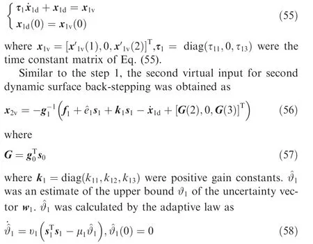
where υ1and μ1were positive constants.
Step 3. Design the dynamic surface back-stepping

Similar to Step 2,x2dwas the output of x2vpass through the first-order filter as
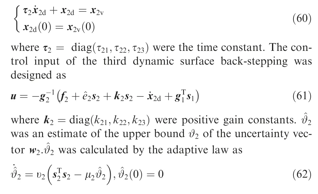
where υ2and μ2were positive constants.Combining the above analysis, the IGCM method based on adaptive dynamic surface back-stepping for HMV in glide phase could be summarized by Eqs. (37), (41), (53), (55)-(56), (58)-(62) as
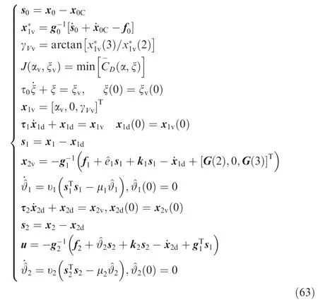
3.2.2. Stability analysis
Before the test of control effects of the IGCM method for HMV, the stability of Eq. (63) need to be proved. Firstly, δ1and δ2were set as the filter errors as

Deriving δiyielded

Set Δi=-˙xivi=1,2. Then Δihas an upper bound Eq.(34) as
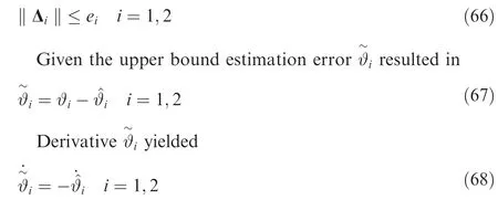
Combining the Eq. (58) and the Eq. (62) into the Eq. (68)yielded
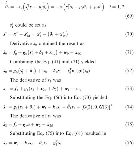
Combining the Eqs. (71), (73), (75), (69) and (65), the closed-loop system with the IGCM method in Eq. (63) could be obtained as
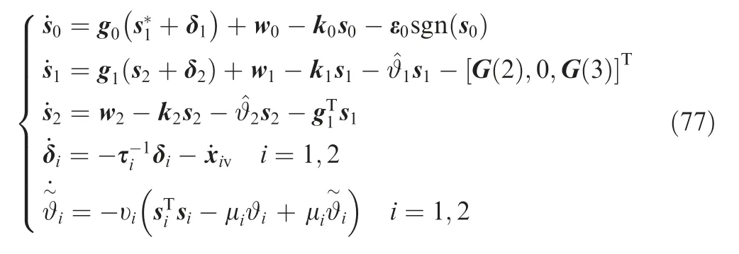
The Lyapunov function was the sum of each subsystem as

The derivative of Lyapunov function with respect to time yielded
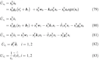
It was acknowledged that

Because ki,i=0,1,2 were the diagonal matrixes, then we can obtain the results as

where kiminwas the minimum value of the diagonal elements in each gain matrix ki. According to the Eq. (34), w0was bounded as

While ϑ0was a positive constant, it could be obtained as

and

The follow inequality existed as

only if

Combining Eqs. (86) and (88), the following inequalities were true

Because

and

Combine the Eq. (85), Eq. (93), Eq. (94) and Eq. (80)yielded

Considering that

Substituting Eq. (85) and Eq. (96) into Eq. (81) yielded
Combine Eq. (65) and Eq. (82) yielded

Combine Eq. (69) and Eq. (83) yielded

Derivative Eq.(92),Eq.(95),Eq.(97),Eq.(98)and Eq.(99)resulted in
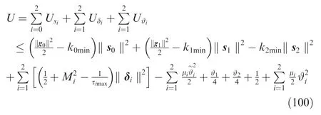
Set a positive constant Ω as

In the I/O models of Eqs. (12) and (25), g0and g1which were the influence matrixes of input variables satisfied the inequalities as

When the parameters in the control law Eq. (63) and Eq.(90) were designed as

where γ was a positive constant. The derivatives of Lyapunov function in Eq. (78) of time satisfied as

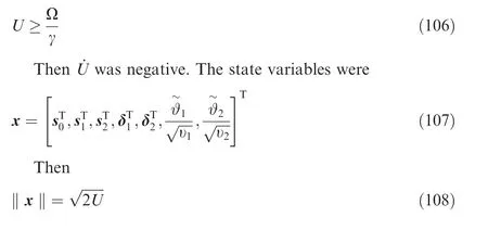
Then the following inequality was proved as

when
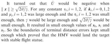
4. Test and analysis
4.1. Effectiveness of IGCM method
The effectiveness of the IGCM method of Eq. was verified by the numerically controlled experiments in glide phase. It was essential to set parallel groups consisted of Hypersonic Morphing Vehicle (HMV) and Hypersonic Un-Morphing Vehicle(HUMV) to identify the effects of morphing technology.Besides,for illustrating the effects of the morphing technology over the large flight envelop, three fight mission with different target positions and initial velocities were set in Table 3.Table 4 presented the initial variables and limited values of HMV and HUMV. Table 5 showed the optimized values of parameters in IGCM method of Eq. (63).
Considering that the response speed of HMV in rotational loop was limited, the commands’ amplitudes, angular rates of the attack angle, the bank angle, the fin deflections and the morphing rate were set in bounded intervals as
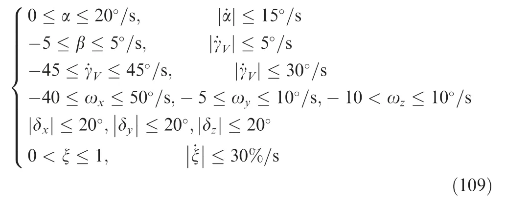
Based on aforementioned assumptions, the parallel controlled experiments have been treated into two groups of HMV and HUMV during three cases. The direct outcome was represented visually by figures below.
The terminal variables values of the six parallel controlled experiments at the landing time in the gliding phase were briefly summarized in Table 6.
In Table 6,Δi,i=x,y,z measured the total amount of three axis fin deflection angles was defined as

From Case 1 to Case 3, the flight ranges were 2984 km,6018.8 km and 8374.9 km respectively, and the altitudes were decreased from 53 km to 50 km, 70 km to 40 km, 60 km to45 km respectively. The three cases represented three gliding modes of different flight ranges and altitudes to verify the effectively of IGCM method in gliding phase over the large flight envelop.
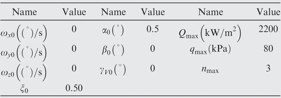
Table 4 The initial variables and limited values of the IGCM.
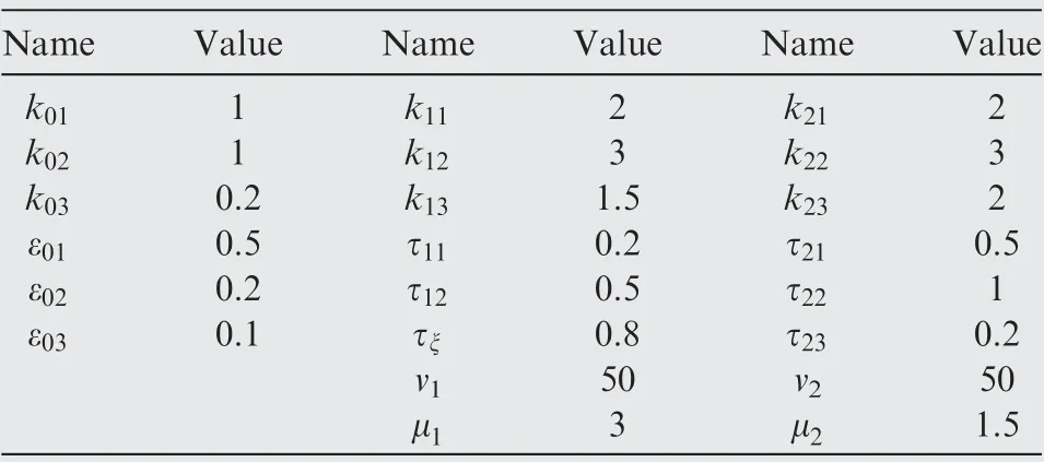
Table 5 Parameter optimization value of IGCM method.
As showed in Figs. 6(a) and (b), both of the HMV and HUMV flied from the starting point to the preset target smoothly in three cases.Fig.6(c)presented that the difference of longitude and latitude between the end point and the preset target point were both very small for HMV and HUMV in three cases. The changes of longitudes, latitudes and altitudes were almost identical for variable and HUMVs. One of the major advantages of the IGCM method designed by adaptive dynamic surface back-stepping method was revealed that it could overcome coordination problem caused by morphing effect on the guidance and control systems so as to complete the stable flight control task with high accuracy in glide phase for HMV.
Besides,it could be seen from Table 6 that the miss distance dm and the landing deviation of HMV was slightly larger than HUMV in three cases. However, the flight time of HMV was less due to the velocity difference between HMV and HUMV.Besides, from Case 1 to Case 3, the time differences increased with the flight ranges.
From the Fig. 6 (d), the morphing rate of HUMV remains unchanged at 0.5 while the morphing rate of the morphing vehicle changes according to the morphing commands of the IGCM method in three cases. It was apparent from the Fig. 6 (d) that the morphing rate decreases from 0.5 to 0 in the beginning.In this state,the attack angle and morphing rate met the aerodynamic lift coefficient requirements and kept theaerodynamic drag coefficient minimum. As showed in Fig. 4,because the Mach of the vehicle was larger in the initial stage,the span kept to minimum value to result in a smaller drag coefficient. As the Mach decreases gradually, the morphing rate rises from 0 to 1.Because when the Mach declined in three cases,the lift-drag ratio in Fig.4 increased with the increase of the span. As a result, the morphing rate remains the largest and the drag coefficient was the smallest.

Table 3 Initial positions, velocities and target positions in three cases.

Table 6 Definitions and values of terminal variables of parallel experiments in three cases.
Fig. 6 (e) presented that the variation velocity path angle and the velocity yaw angle of HMV and HUMV were almost same in three cases.The commands of velocity path angle and velocity yaw angle were tracked smoothly to satisfy the flight requirements. While the span sharply rose, the lift changed suddenly which resulted in a small oscillation of velocity path angle. But the IGCM method quickly stabilized the velocity path angle in three cases.
The velocity variations of HMV and HUMV were quite different in three cases. Because the IGCM method changed the lift-drag ratio to maximum by the variation of the span of the vehicle according to the flight command, the drag coefficient of the HMV was less than HUMV.From Table 6,the terminal velocities of the HMV and HUMV was 3365 m/s and 2922 m/s in Case 1, 2267.6 m/s and 2007.2 m/s in Case 2,1925.9 m/s and 1452.9 m/s in Case 3. It showed clearly that the morphing characteristic reduced the velocity loss of the MHV by 15.16%, 12.9% and 32.8% than HUMV in three Cases respectively. The HMV greatly increased the terminal flight velocity which depicted a larger range and larger terminal attack energy under the same conditions.
Fig. 6 (f) showed that the attack angle increased slowly to satisfy the lift command in whole process of gliding flight with HMV and HUMV because the dynamic pressure decreases gradually with the decrease of velocity in three cases.The variation of attack angle of HMV was gentler than HUMV because the variant of lift command was accomplished by both the span variant and the change of attack angle. In the latter flight, the lift changes suddenly due to the sharply increase of the span which lead to a concussion of the attack angle change. Because of the BTT turning mode, the variation of sideslip angle was keeping zero almost all the time in the cases of HMV and HUMV. A similar trend was observed in bank angle. Since the azimuth error at the initial time, the bank angle in the initial stage showed a sharp fluctuation. Fortunately, the IGCM method designed for HMV showed a quick response to the bank angle in three cases.
From Figs.6(g)and(h),there was no difference in the variation of angular rates between HMV and HUMV in three cases and the angular rates was nearly always maintained at 0 which result in the small change of fin deflections of rolling and yawing. According to Table 6, the use amount of rolling fin deflection and yawing fin deflection was small. However,the pitching fin deflection increases slowly for maintaining stable flight. After the sharp increase of the span, the usage amount of pitching fin deflection angle of HMV was larger than HMV. Because the increase of the span increased the pitching moment coefficient of the HMV, then a larger pitching fin deflection angle was needed to maintain the longitudinal moment balance in three cases.
The above figures lead us to the conclusion that the IGCM method solved the two questions proposed in the Section 1.The two parallel controlled experiments of hypersonic HMV and hypersonic HUMV revealed that the morphing characteristic could be treated as control input to reduce the energy loss and flight time to obtain a larger range and terminal attack energy. Besides, the IGCM method designed was effective for HMV over the large flight envelop in gliding phase with overcoming the coupling difficulties caused by the guidance system, attitude control system and morphing system.
4.2. Robustness of IGCM method
The robustness of the IGCM method must be tested under aerodynamic uncertainties for HMV in glide phase. The Monte Carlo experiments were carried out in two parallel controlled experiments that was identical to Section 4.1 and consisted of HMV and HUMV by adding deviations to the aerodynamic coefficient and the atmospheric density in the motion models. The distributions were set as

where v was the uncertainty parameter vector defined as

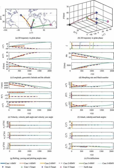
Fig. 6 Variations of the motion variables of HMV and HUMV in glide phase with three cases.
The initial conditions and parameter values were as same as Case 1 in Tables 3, 4 and 5. After 250 simulations, the results were described in Fig. 7 of HMV and Fig. 8 of HUMVs.
The simulation results of Monte Carlo experiments of the two groups were summarized in Table 7.
As it can be seen from Table 7,μ and σ were the mean value and standard deviation respectively. CEP denoted the radius of the circle which center was target point and the vehicle has a 50% probability to land into the circle.
From Fig. 7 to Fig. 8, the IGCM method showed a strong robustness with meeting requirements of guidance system and control system with deviation uncertainties of the aerodynamic coefficient and the atmospheric density.
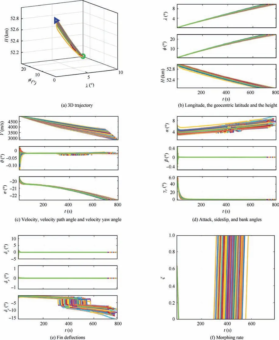
Fig. 7 Variations of the motion variables of HMV in Monte Carlo experiments.
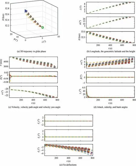
Fig. 8 Variations of the motion variables of HMV in Monte Carlo experiments.

Table 7 Results of landing point in Monte Carlo experiments.
The designed IGCM method maintained the stability of HMV in gliding phase. The standard deviation and CEP values of HMV landing point were larger than the HUMV.Because the influence of the span variation on the guidance and control loop at the same time, it seemed that the variable span weakened the robustness for the uncertainties but it still presented strong robust to parameter uncertainties under morphing technology.Fig.7 showed the significant differences difference of morphing rates of HMV which indicated that the span can be adaptively adjusted under uncertainties. According to Fig. 9 and Table 7, the mean value of velocity at the end point was larger than the HUMV while the standard deviation was smaller than the HUMV. It demonstrated that the morphing characteristics still reduced the velocity loss of MHV and showed a better robustness under uncertainties
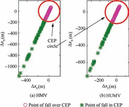
Fig. 9 Variations of landing point distribution in Monte Carlo experiments.
From the above analysis, the effectiveness and robustness of IGCM method was verified by the simulation experiments with two parallel groups in three cases.The results proved that the morphing technology reduced the energy loss for HMV in gliding phase and the IGCM method was effective and robust to reject the disturbance of the guidance and attitude control system caused by the morphing technology.
5. Discussion
The original design intention of HMV was proposed to improve the flight performance by changing the shape to adjust aerodynamic characteristics under different flight conditions. However, the morphing laws under different flight state and disturbance reduction caused by the morphing to the guidance and attitude control system were always the two crucial problems of the HMV. In this paper, through the IGCM method of HMV, the morphing spans were taken as a new extra control input to reduce the loss of velocity loop. The morphing rate was determined by current flight state and the disturbance caused by the morphing systems was rejected by the IGCM method. Therefore, the IGCM method developed in this paper was the first study about the two crucial problems of HMV by integrated designing of guidance, attitude control and morphing system in glide phase.
Despite the aforementioned great advantages there were also some pitfalls.It should be noted that this study has examined only the flight control algorithm in gliding phase for HMV, so the results of the study cannot be taken as evidence for other morphing vehicles or hypersonic vehicles. We had not addressed all feasibility of design and manufacturing of HMV models. A further study could develop a full picture of MHV’s flight control, so additional studies need to be undertaken. For example, it was necessary to examine other flight phases such dive phase and build up more precise geometric models, aerodynamic models and control algorithms.
6. Conclusions
(1) The IGCM method for HMV in gliding phase was proposed in the paper.On the basis of the IGCM models in glide phase, the IGCM method was designed by adaptive block dynamic surface back-stepping method.Besides, the closed loop stability of IGCM method was proved with Lyapunov stableness theory.
(2) The parallel controlled experiments consisted of HMV and HUMV demonstrated that the IGCM method was effective in accomplishing the control task of HMV in glide phase with a very small terminal landing deviation.The most obvious finding to emerge from the results was the terminal velocity of HMV was clearly reduced by 32.8%than HUMV which meant larger flight range,less flight time and larger terminal attack energy for MHV in gliding phase.
(3) Through Monte Carlo experiments, the robustness of the IGCM method was analyzed under the condition of large deviation of aerodynamic parameters and atmospheric density. The results indicated that the IGCM method was much robust with aerodynamic uncertainties.
(4) It had satisfactorily come to the conclusion the that the IGCM method played a role of morphing characteristic in improving the flight performance of HMV in gliding phase and showed effective and robust for flight control system composed of the guidance, attitude control and morphing systems.
(5) The paper provided a deeper insight for the flight control system of HMV. Furthermore, the insight gained from the result would be of assistance to the conceptual development of HMV.
Declaration of Competing Interest
The authors declare that they have no known competing financial interests or personal relationships that could have appeared to influence the work reported in this paper.
Appendix A.(1) Fgcould be expressed in the ballistic coordinate system as

where μ denoted the gravity constant, J=1.5J2was the zonal gravitational coefficient. aewas the semimajor axis of the earth.
(2)Fωecould be expressed in the ballistic coordinate system as

where ωewas the earth’s rotation rate.
(3) Fkcould be expressed in the ballistic coordinate system as
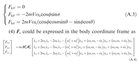
where HVwas the transformation matrixes of the velocity coordinate frame to the ballistic coordinate.BVwas the transformation matrixes of the velocity coordinate frame to the body coordinate.
(5) Mscould be expressed in the body coordinate frame as
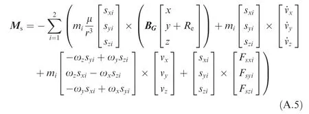
where BGwas the transformation matrix of the launch coordinate frame to the body coordinate frame. [x,y,z]Twere the three components in the launch coordinate frame of the Earth’s radial diameter r,which was expressed as r= [x,y,z]T.
 CHINESE JOURNAL OF AERONAUTICS2021年5期
- CHINESE JOURNAL OF AERONAUTICS的其它文章
- Ferrofluid moving thin films for active flow control
- Preliminary study on heat flux measurement data of TT-0 flight test
- An analysis and enhanced proposal of atmospheric boundary layer wind modelling techniques for automation of air traffic management
- Jet sweeping angle control by fluidic oscillators with master-slave designs
- Hot deformation behavior and microstructure evolution of the laser solid formed TC4 titanium alloy
- Electrochemical trepanning with an auxiliary electrode
