Core reinforcement design for improving flexural energy-absorption of corrugated sandwich composite structure
Yiru REN, Yabin DENG, Hongyong JIANG,*
a State Key Laboratory of Advanced Design and Manufacturing for Vehicle Body, Hunan University, Changsha 410082, China b College of Mechanical and Vehicle Engineering, Hunan University, Changsha 410082, China
KEYWORDS Energy absorption;Finite element;Reinforcement;Sandwich structure
Abstract To strengthen Specific Energy-Absorption (SEA) behavior of Sandwich Composite Structure (SCS), a kind of light-weight vertical stiffener is proposed for the corrugated core. The vertical stiffener, embedded in the corrugated core, can not only absorb part of energy but also simultaneously enhance Energy-Absorption(EA)of other components.The Hashin damage model considering the shear stress and ductile damage model is adopted to predict the failure of carbon fiber face-sheets and aluminum-core, respectively. The perfect bonding is modeled for interfaces between the face-sheet and core due to little realistic debonding.The finite element model is verified by available data of conventional SCS.To obtain more design ideas,several stiffeners with different thicknesses, numbers, and positions are investigated. From the predicted results, both the flexural load and deformation of SCS correlate well with experimental results.It is highlighted that the SCSs with different vertical stiffeners exhibit 9.74%-58.48%higher SEA than the SCS without stiffener.The complex reinforcement mechanisms are extensively revealed by underlying coupling EA and deformation mechanisms.Structural parameter analysis shows that the thickness and number have significant effects on the flexural behavior and SEA of reinforced SCS.
1. Introduction
Sandwich Composite Structures (SCSs) generally consist of two high-strength face-sheets and a light-weight core. It enables sandwich composite structures to have higher specific strength/stiffness, energy-absorption, and designability.1-6Therefore,SCSs have been widely applied in various engineering fields such as aerospace,vehicle,and marine.7-14Although the SCSs have a good application prospect, the most major limitations for more extensive applications are (A) sensitivity of mechanical properties to structural deformation/damage and(B)mechanical property mismatch between adjacent components. Hence, it is of significance to obtain an insight into damage mechanisms of core and reinforce the conventional core to improve the damage resistance and alleviate the mismatch.
Numerous experimental and numerical studies on sandwich composite structures with different cores have been conducted to reveal typical damage modes and mechanisms.15,16For instance,Refs.15-19studied the impact,compressive and indentation behavior of a sandwich structure with the honeycomb core,foam core,and corrugated core.From the recorded damage discoveries, it was shown that under any loading conditions, the face-sheet presented damage preferentially. Before these main damage modes including fiber breakage, matrix cracking, and interlaminar delamination occurred, the maximum carrying limitation could be identified. However, there are a lot of differences after the first peak in the loaddisplacement curve due to different types of core.For the foam core, the main damage modes were summarized as foam densification, foam shearing, foam crushing, and foam crack.16,20The axial crushing and buckling,and honeycomb densification were revealed for the honeycomb core.6,9,15For others, the metal core characterized by different topological structures such as corrugated,grid,X-frame,Y-frame,etc.,typically presented large amounts of plastic hinges, local buckling modes,etc.13,21-25It was found that the plastic deformation greatly contributed to structural energy-dissipation. Therefore, the stable energy-absorption for any sandwich after the peak load can be determined by the main core damage modes.Due to the importance of core damage,Jiang et al.24inserted a simple and effective stiffener into the core sandwich and changed the core damage process to enhance the Specific Energy-Absorption(SEA) efficiency. From the point of view of structural design,it is thus enlightened that some typical core configurations can be redesigned and reinforced to change or induce expected damage modes. This may be more effective to improve the energy-absorption of sandwich with limited weight, thereby lowering the cost of materials. So, it is of significance to conduct extensive investigations into structural reinforcement design.
Up to now,there has reported many reinforcement designs of the core to further improve the mechanical performance of SCSs.24,26-31Thereinto, a common reinforcement design method at the structural-scale has been frequently adopted,which is that the additional material or stiffener is introduced into appropriate and weak positions in the core. For instance,Wang et al.28proposed a honeycomb structure embedded with the inclined cells at a certain angle, where the different honeycombs exhibited different mechanical behavior. Lei et al.29designed a multi-layer graded sinusoidal corrugated core.From the result of the experiment and simulation,it effectively enhanced the energy absorption capability of the sandwich structure. Ma et al.30reported that a high damping layer was inserted into the middle layers of the corrugated-core sandwich panel so that the increased stiffness and high damping capacity were obtained.Sun et al.22and Shi et al.25studied the compressive and flexural behavior of honeycomb sandwich composite structure reinforced by a grid stiffener. It was found that the energy-absorption of the sandwich was significantly improved not only for compressive load but also for the flexural load.Meanwhile, the temperature also has a great effect on the bending resistance of carbon fiber reinforced polymer composites. Lei et al.31found that the cryogenic temperature affected the toughness of the matrix and the laminates’ failure mode.As the temperature decreased,the bending properties had over 50% increment.
As previously studied, most researches mainly focused on the improvement of structural mechanical properties through the introduction of additional structure/mass. However, (A)there were few studies involving the enhancement of specific performances such as specific stiffness, specific strength,specific energy-absorption, etc., which are very important for aerospace and electric vehicle. On the other hand, (B) a large mechanical property mismatch between hard and stiff carbon-fiber face-sheet and compliant metal core may affect the structural integrity during the damage process. Hence, it is greatly necessary to carry out prospective follow-up investigations into the reinforcement design of the core in a sandwich.
In general, the core of sandwich, such as corrugated, Xframe, and Y-frame, has numerous hollow areas, where thus these hollow areas can be fully utilized to reinforce the core.In view of our previous study,24although the SEA with an increase of 23.83% has been obtained by introducing a stiffener into the corrugated core, the total mass still increased by about 13.1%. Therefore, the present work redesigns the stiffener to reduce the increased structural mass and simultaneously improve the SEA as much as possible. Then, based on the redesigned vertical stiffener, the effects of the structural parameters including the stiffener thickness,number,and position are analyzed by numerical model. According to comprehensive comparisons, differences between the one with stiffener and without stiffener, the coupling deformation modes and coupling energy-absorption are deeply studied to reveal the reinforcement mechanisms. Finally, these obtained conclusions could be used as valuable guidelines for the reinforcement design purposes in sandwich energy-absorbing devices.
2. Core reinforcement design
2.1. Conventional corrugated core
Fig.1 shows the configuration of conventional corrugated core in sandwich.The sandwich composite structure is composed of the corrugated core and two composite face-sheets. Both the top and bottom face-sheets are fabricated by unidirectional carbon fiber/epoxy(T700/3234)materials,19where their stacking sequences are [0°/90°/0°/90°]s. The core, made by a 2A12-T4 aluminum sheet,19has 3-unit cells with trapezoid.The total length L and width W of the conventional corrugated core are respectively 300 mm and 96 mm, and t=1 mm. W1=7 mm,W2=24 mm, W3=32 mm, H=12.85 mm and θ=55°.According to Ref.19, the referenced values of material parameters are listed in Table 1.19,32The flexural behavior of the conventional corrugated core sandwich is selected as control data.
2.2. Reinforced corrugated core

Fig. 1 Geometrical configuration and dimension of conventional corrugated core in sandwich.
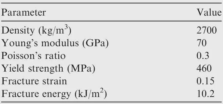
Table 1 Numerical material parameters of aluminum alloy sheets (2A12-T4).19,32
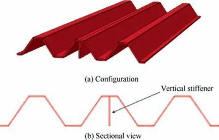
Fig. 2 Geometrical configuration of corrugated core reinforced by a vertical stiffener.
The conventional corrugated core is reinforced by a stiffener that is vertically embedded in the conventional corrugated core, as shown in Fig. 2. The length and height of the vertical stiffener are 300 mm and 12.85 mm, respectively, which are in accord with the sizes of the conventional core. The stiffener presently has the same material properties as the conventional corrugated core. This type of stiffener not only is simple and effective in manufacture, but also only introduces relatively low structural weight to contribute to SEA.
Due to the introduction of additional structures, the SCS reinforced by a vertical stiffener may exhibit more complicated deformation, failure, and dynamic behavior. To reveal the reinforcement and deformation mechanisms, several vertical stiffeners are designed,which include different thicknesses,different numbers, and different positions, as shown in Fig. 3.These parameters of similar stiffeners have been proved to have significant influences on the flexural behavior of sandwiches.24This is because the increases of thickness and number can increase the total weight of the sandwich. Hence, the related sensitivity analysis aimed at lighter vertical stiffener is conducted in this work.Here,four types of thickness including 0.25 mm, 0.50 mm, 1.00 mm, and 2.00 mm are considered(Fig. 3(a)), while three different numbers including one, three,and five stiffeners are considered (Fig. 3(b)). Three positions including position I, II, and III are considered (Fig. 3(c)), in which the structural weight is constant for the change of position.
3. Numerical modeling
3.1. Finite element model
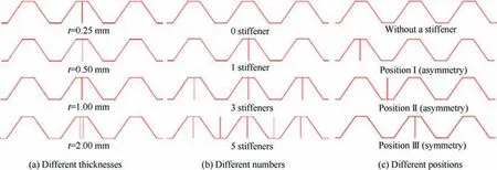
Fig. 3 Configurations for core reinforced by vertical stiffener with different thicknesses, numbers, and positions.
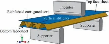
Fig. 4 FEM of corrugated sandwich composite structure subjected to three-point bending.
The Finite Element Model(FEM)of the corrugated sandwich composite structure under three-point bending is composed of the reinforced corrugated core, two face-sheets, one indenter,and two supports, as shown in Fig. 4. Due to little deformation, the indenter and supports are regarded as rigid bodies that are modeled with 4-node 3D bilinear rigid quadrilateral elements (R3D4). According to testing, the three-point bending is implemented with the constant loading speed,19,33,34and the strain-rate sensitivity is neglected due to the quasistatic loading. Six degrees of freedom of supporters are restricted, while the indenter only has one degree of freedom in the loading direction. For deformed bodies, both of facesheets and reinforced corrugated core are modeled with shell elements (S4R). S4R represents 4-node reduced integration thick shell with the hourglass control, which can not only reduce the computation cost but also meet the accuracy requirement. The pure corrugated core (without a stiffener)is meshed with 4400 S4R elements while each face-sheet is meshed with 2500 S4R elements. Each vertical stiffener has a similar mesh density as the pure corrugated core.The materials of deformed parts can refer to Tables 119,32and 2,19,34,35respectively.For the interaction,the general contact algorithm is adopted in the whole model, which simulates the friction interaction. The friction coefficient is defined as 0.2. Based on He et al.’s experimental failure modes,19little interfaces debonding was reported, in which they simplistically modeled the interface with the perfect bonding. The perfect bonding is considered by employing the surface-based tie constraints at the interfaces. Hence, the interfaces between the core and face-sheets are also defined with the perfect bonding in this work. The flexural response of the corrugated sandwich composite structure under three-point bending is simulated through the commercial software ABAQUS/Explicit.
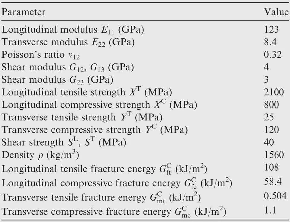
Table 2 Numerical material parameters of carbon fiber facesheets (T700/3234).19,34,35
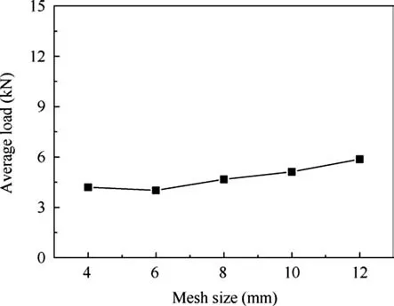
Fig. 5 Mesh convergence analysis for conventional core case:average load.
3.2. Mesh convergence analysis
Mesh size has a significant effect on the calculation efficiency and accuracy. Thus, it is necessary to carry out the mesh convergence analysis. Five types of mesh sizes (4.0 mm, 6.0 mm,8.0 mm, 10.0 mm, 12.0 mm) are chosen to evaluate the effect of the mesh size. Taking the SCS without a vertical stiffener as an example, the average loads are compared among the cases with five mesh sizes in Fig. 5. It is shown that the model with large mesh sizes presents relatively higher average load.When the mesh size decreases to 6.0 mm, the average load tends to be stable.
3.3. Modeling of mechanical characteristics
3.3.1. Aluminum core
The corrugated core and stiffeners, fabricated by aluminum,can be regarded as an isotropic elastic-plastic material, which exhibits the metal plastic deformation during the flexural process. To capture accurate initial damage and evolution of mechanical performance, the ductile damage model, being a phenomenological model, is adopted.36,37The value of the state variable ωDis used to represent the initiation of metal damage.When ωD=1,the metal damage is immediately activated. ωDis calculated as
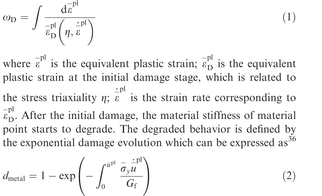
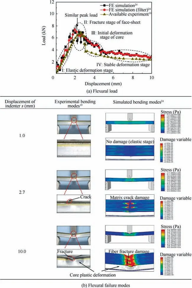
Fig. 6 Comparison of the flexural responses of conventional corrugated core SCS between experiment19 and previous simulation.24
where dmetalis the damage variable of metal, describing the degree of degradation, ranging from 0 to 1; u-plis the relative plastic displacement; σ-yis the equivalent yield stress;=, where Lcis the characteristic element length; Gfis the fracture energy dissipation. Once dmetal=1, the failure elements will be deleted. The material parameters used for numerical simulation are listed in Table 1.19,32
3.3.2. Carbon fiber face-sheets
Four main failure modes of carbon fiber face-sheets are fiber tensile failure, fiber compression failure, matrix tensile failure and matrix compressive failure.Hence,the 2D Hashin damage criteria considering the shear contributions is adopted38,39to capture main failure modes, which is given by
Tensile fiber mode:

Compressive fiber mode:

Tensile matrix mode:

Compressive matrix mode:
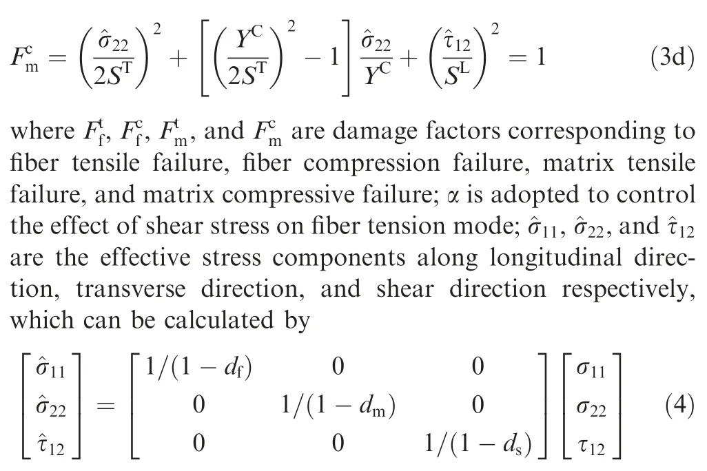
where df, dm, and dsare fiber, matrix, and shear damage variables respectively; σ11, σ22, and τ12are the true stress components along longitudinal direction, transverse direction, and shear direction respectively.Once any Hashin criterion is satisfied, further loading will cause the degradation of material stiffness. In this model, a linear damage evolution combined with fracture energy method is adopted,36,40which are expressed as
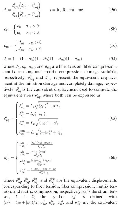

3.4. Validation of FEM model
Comparisons of the flexural responses of the conventional corrugated core SCS between experiment and simulation are used to validate the FEM,as shown in Fig.6.The simulated results are obtained from our previous study24and the experimental results are obtained from Ref.19. Obviously, it is shown from Fig. 6(a) that the simulated flexural load responses, such as peak load and stable load, are basically consistent with experimental results but with minor fluctuations.Both the simulated and experimental curves are divided into four stages,including(I) elastic deformation stage, (II) fracture stage of fiber facesheet, (III) initial deformation stage of core, and (IV) stable deformation stage.24From Fig. 6(b), it is shown that the simulated results also correlate well with experimental observations. When the displacement of the indenter is 1.0 mm,there is no damage occurring, which can be seen in the results of the experiment and simulation.With the increase of the displacement, the failure models such as matrix crack damage,fiber fracture damage,and core plastic deformation have gradually appeared. Therefore, it is proved that the FEM model can be used to predict the flexural behavior of reinforced corrugated core sandwich composite structures.
4. Comparison of reinforced and conventional SCS
4.1. Flexural load-displacement response
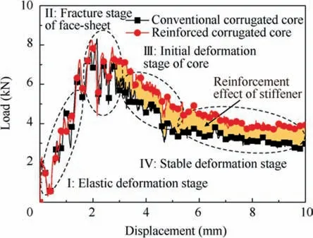
Fig. 7 Comparison of flexural load-displacement response between conventional core and reinforced core.
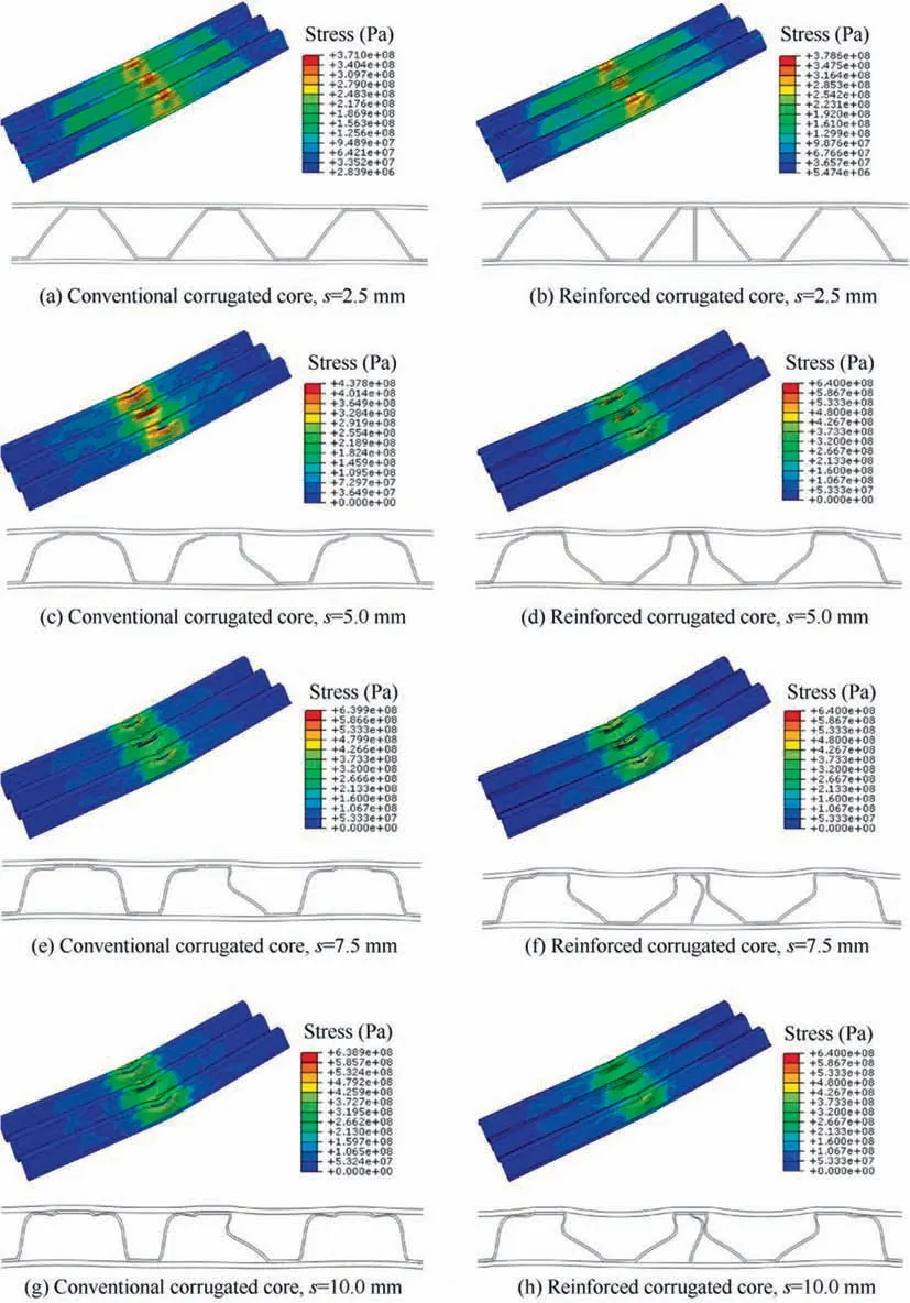
Fig. 8 Deformed processes of SCS conventional corrugated core and reinforced corrugated core.
A comparison of the flexural load-displacement response between the conventional core and reinforced core is shown in Fig. 7. It is shown that both curves have similar variation trends which also include four stages mentioned in 3.4 section.At first,both curves almost coincide at the elastic deformation stage and the face-sheet damage stage. Before the top facesheet is damaged, there is no damage occurring in the core.This is because the top face-sheet with the thickness of 1 mm is too thin. Hence, the initial flexural response of SCS mainly depends on the carrying of the top face-sheet.During the damage process of the top face-sheet,the matrix cracking and fiber fracture progressively occur, leading to large fluctuations.After that, the corrugated core presents the plastic deformation. Expectedly, it is found that the flexural load for reinforced core is higher than that of conventional core during the displacement from 3 mm to 10 mm. The increased load can be seen from the orange shadow in Fig.7.This is obviously due to the reinforcement effect of the vertical stiffener. Interestingly, during the core deformation, the load curve of the reinforced core seems to be parallelly moved up from the original curve. It is thus illustrated that the vertical stiffener exhibits an outstanding reinforcement capacity.
4.2. Reinforcement and coupling deformation
As analyzed above, the flexural carrying-capacity of the SCS has great improvement when only a simple vertical stiffener is embedded. However, the stiffener complicates the deformation mode of core. To understand the strengthening mechanism, the deformed processes of SCS with conventional and reinforced corrugated core are compared in Fig. 8. When s=2.5 mm, both SCSs present little deformation. When deforming from s=5.0 mm to s=10.0 mm, several plastic hinges appear, but their deformation modes are different.Fig. 9 details the analysis of core deformation, taking s=10.0 mm as an example. From Fig. 9(a), the core without the vertical stiffener can be divided into deformation region A(the middle of the core) and deformation region B (the right side of the core).For the deformation region A,the right oblique planes of the core are inward-concave and the plastichinge rotation angle is θ1, while the left side is outwardconvex. For the deformation region B, both oblique planes of core are outward-convex and plastic-hinge rotation angle is θ2, both of which gradually increase with further the displacement δ2. This phenomenon can be also observed from the experiment.41For the reinforced core (Fig. 9(b)), it can be divided into deformation region C (there is a stiffener)and deformation region D(there is no stiffener).For the deformation region C, both oblique planes of core are inwardconcave with a plastic-hinge rotation angle θ3. As compared with the outward-convex mode (Fig. 9(a)), the inwardconcave leads to a larger plastic-hinge rotation angle θ3≈θ1>θ2. Hence, the reinforced core can dissipate the energy through the plastic-hinges. In addition to that, the deformation mode of stiffener is a large buckling mode which directly determines the reinforcement of SCS. Further, during the flexural process, the curving stiffener contacts one oblique plane of core and affects the deformation of core. This also leads to the reinforcement of carrying-capacity of core. For the deformation region D, there is also an inward-concave oblique plane, thereby absorbing more energy.
4.3. Coupling energy-absorption mechanisms
The total energy absorption of the SCS with conventional core and reinforced core is compared in Fig. 10. It is found that before the displacement of 3 mm, the stiffener does not have obvious effect on the EA of SCS.However,after that,the stiffener starts to play a reinforced role,causing that SCS with the vertical stiffener presents higher EA than the conventional core. Further, the differences of EA between them gradually increase. When the displacement is 10 mm, an increase of 18.58% in EA is recorded for the reinforced core. Therefore,it is proved that the SCS reinforced by a vertical stiffener has higher EA capacity.
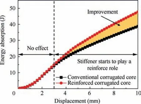
Fig. 10 Comparison of total energy absorption between conventional and reinforced corrugated core.
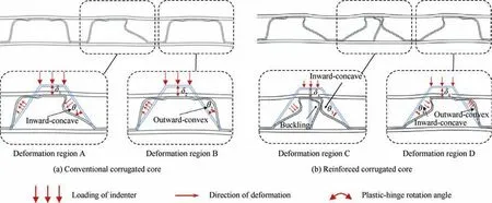
Fig. 9 Analysis of reinforcement and coupling deformation mechanisms, taking s=10.0 mm as an example.
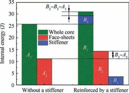
Fig. 11 Internal energy of each component in SCS with and without a stiffener(An and Bn represent the value of IE of different components).
Further, the improvement of EA can be explained by the underlying coupling mechanisms, as shown in Fig. 11. The Internal Energy (IE) of each component in the SCS with and without a stiffener are presented in Fig. 11, where the IE mainly represents the energy caused by damage. Compared with the conventional core,both the whole reinforced core and its adjacent face-sheets present higher IE, which has the relation of B1>A1and B2>A2. As shown by the blue area, it represents the IE of pure stiffener when using the reinforced core.It is illustrated that the vertical stiffener itself can absorb a part of energy B3. By comparison, there are two relations:B1-A1>B3and B2>A2. It can be explained that the introduction of stiffener can cause pure core and face-sheets to absorb more energy, which is attributed to the coupling energy-absorption. Under the role of coupling EA, the values of increased EA of the pure core and face-sheets are B1-B3-A1and B2-A2respectively.
4.4. Specific energy absorption
The SEA is the most critical parameter to measure the energyabsorption capacity of the structure, which is also the present design purpose. Table 3 lists the total EA, mass, and SEA of SCS with and without stiffener.From Table 4,it is shown that the EA for the reinforced SCS improves by about 18.58%.Particularly, it is noted that, when the stiffener is introduced, the increased total mass is only about 0.005 kg,being 3.44%of the original total mass. The increased mass in this design is lower than that of Jiang et al.’s design,24which showed an increase of 13.1% in mass. Because of the large increase of EA but little increase in mass, the SEA of SCS can be improved by about 14.44%. Thus, it is meaningful to design such a vertical stiffener to reinforce the flexural energy-absorption capacity of SCS. Due to the high sensitivity of structural parameters on the flexural behavior,24the structural parameters of the vertical stiffener are studied in the following.
5. Discussion
5.1. Structural parameter analysis
Although the stiffener can greatly reinforce the SCS, typical structural parameters of stiffener have significant influences on the flexural behavior of SCS. To identify higher EA and SEA, the thickness, number and position of the vertical stiffener are deeply studied. Fig. 12 shows the effects of typical parameters of the stiffener, including thickness, number, and position, on the load response and internal energy of each component.Fig.13 shows deformation modes of SCS with different thicknesses, numbers and positions.
For the thickness of stiffener, Jiang et al.24have reported that increasing the horizontal stiffener can improve the EA of SCS but reduce the SEA due to higher structural weight.They concluded that the relatively thin stiffener presented higher SEA than the thick stiffener. However, it is different from the present vertical stiffener. It can be shown from Fig. 12(a) that the thickness of stiffener presents little effect on the flexural load of SCS before the deformation of core.Nevertheless,the stiffener can greatly increase the flexural load of SCS with the increase of thickness when the core starts to deform. As concluded above, the stiffener can improve the EA of other components. Hence, it is also observed in Fig. 12(a) that the increase of thickness can increase the EA of face-sheets, whole core, and stiffener, but the EA of whole core and stiffener tend to be stable or slightly decreasing.This can be explained by the deformation modes as shown in Fig. 13(a), indicating that 0.25 mm, 0.50 mm, and 1.00 mm thick stiffeners present large buckling deformation. However,there is not obviously buckling occurring in the stiffener with the thickness of 2.00 mm. Therefore, it illustrates that the thicker stiffener has higher carrying capacity, being also responsible for the increasing trend in terms of load.

Table 3 Total EA, mass and SEA of SCS with and without stiffener.

Table 4 Total energy absorption, mass, and specific energy absorption for all cases.
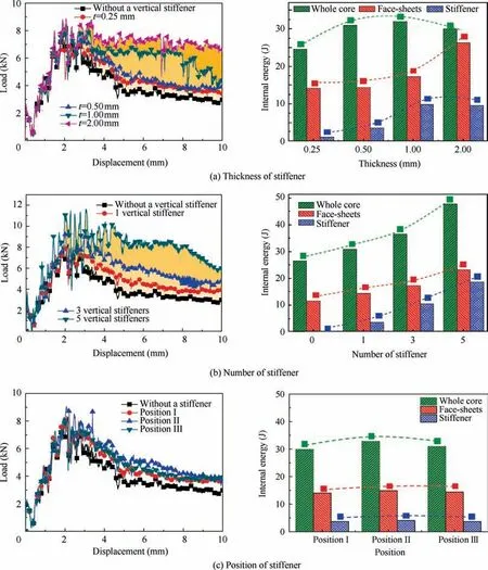
Fig.12 Effects of typical parameters of stiffener including thickness,number,and position on the load response and internal energy of each component.
For the number of stiffeners,it can be shown from Fig.12(b)that the increase of stiffener numbers can significantly increase the flexural load and EA of SCS during the whole process.This is mainly due to the fact that more vertical stiffeners make the core exhibit higher axial carrying capacity. Differently, there are lots of large fluctuations in curves during the elastic stage and the fracture stage of face-sheets. The reason is attributed to too stiff core when using five stiffeners.Due to the coupling EA,increasing the number of stiffeners can increase lots of EA of whole core, face-sheets, and stiffener, which greatly contributes to the total EA. By computation, it is shown that the reinforced SCS with five stiffeners presents 58.48% higher SEA.In terms of deformation modes,it is shown in Fig.13(b)that different numbers of stiffener present similar buckling deformation mode.The number of deformed stiffeners can obviously affect the energy dissipated by plastic deformation.
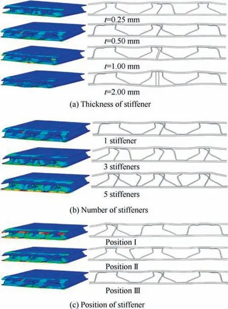
Fig. 13 Deformation modes of SCS with different thicknesses,numbers and positions.
For the position of stiffener, it is found in Fig. 12(c) that,despite the asymmetric positions, the stiffeners vertically placed at any position can improve the flexural load of SCS.However, the position of stiffener has relatively less effect on the flexural load and EA of each component than the thickness and number. Three different vertical positions present similar flexural load, where the position close to center shows a slightly higher flexural load. For the horizontal stiffener, the previous study24reported that the symmetric position showed higher and more stable flexural load than asymmetric positions. This is due to the fact that the deformation of the horizontal stiffener is highly coupled to that of the core, and different positions have a great effect on the flexural behavior of the core. However, according to the final deformation(Fig. 13(c)), it is shown that the present vertical stiffeners placed at any position present similar buckling deformation.Thus, it is indicated that the symmetric and asymmetric positions have similar effects on the deformation of the core, but the position close to the center may be better.
5.2. Comprehensive evaluation and design suggestion
The total energy absorption and specific energy absorption of SCSs are concluded to evaluate the energy absorption capacity of reinforced SCS with different parameters.Table 4 lists total energy absorption,mass,and specific energy absorption for all cases. According to the evaluations, some design suggestions are given as follows.
The increase of number is, in fact, equal to the increase of thickness, so the thickness is important for the design. It is shown that the structural mass is greatly increased, such as 14.48% and 17.93%, when increasing the thickness and number of stiffeners. Hence, the thin vertical stiffener and fewer numbers are recommended to improve the SEA of SCS if pursuing the increase of EA but simultaneously considering lower mass. Otherwise, increasing the thickness and number of stiffeners may be the better method to improve the energyabsorption capacity. However, the light weight and high strength are the focus of the design in engineering applications,especially for aircraft and electric vehicle.42,43Further,various thin-walled structures have been in the spotlight all the time due to their outstanding specific stiffness/strength and SEA.According to most of studies,most of the thicknesses are lower than 1.00 mm for thin-walled metal structures13,19and 2.00 mm for thin-walled composite structures.44-46Therefore,0.50 mm and 1.00 mm metal stiffeners, presenting the SEA increase of 14.44% and 35.02% respectively, may be more appropriate.Finally,based on the results of the SEA,the position of stiffener is suggested to be better placed close to the center of the corrugated core.
6. Conclusions
(1) This work designed a simple and effective stiffener to reinforce the corrugated core sandwich composite structure with the purpose of improving the SEA.By making use of the axial crushing capacity of plate structure, a stiffener is vertically embedded in the conventional corrugated core. Through the buckling plastic deformation of the stiffener, more energy is dissipated. Hence, it is found that the reinforced core presents 14.44% higher SEA than the conventional core but only increasing the mass by 3.44%.
(2) The reinforcement mechanism is revealed as the higher axial crushing capacity of stiffener and coupling deformation, which can affect the deformation of other components and thus improve the EA of each. To reveal dynamic behavior, sensitivities of main parameters of stiffener were studied. It is concluded that thickness and number of stiffeners have great effects,but the position has relatively slight effect on the EA and SEA of SCS. Notably, the thickness and number greatly increase the structural mass. Due to much improvement in EA, the SEA of SCS still increases with the increase of thickness and number, where the SEA can be here improved by 58.48% maximally.According to specific requirements, designs of the present vertical stiffener and previous horizontal stiffener24with befitting parameters can be used to provide some ideas for the enhancement design of the sandwich.
Declaration of Competing Interest
The authors declare that they have no known competing financial interests or personal relationships that could have appeared to influence the work reported in this paper.
Acknowledgements
This study was supported by the Foundation for Innovative Research Groups of the National Natural Science Foundation of China(No.51621004),the National Natural Science Foundation of China (No. 11402011) and Hunan Provincial Innovation Foundation for Postgraduate, China (No.CX2018B204).
 CHINESE JOURNAL OF AERONAUTICS2021年5期
- CHINESE JOURNAL OF AERONAUTICS的其它文章
- Ferrofluid moving thin films for active flow control
- Preliminary study on heat flux measurement data of TT-0 flight test
- An analysis and enhanced proposal of atmospheric boundary layer wind modelling techniques for automation of air traffic management
- Jet sweeping angle control by fluidic oscillators with master-slave designs
- Hot deformation behavior and microstructure evolution of the laser solid formed TC4 titanium alloy
- Electrochemical trepanning with an auxiliary electrode
