Scaling effects on combustion modes in a single-side expansion kerosene-fueled scramjet combustor
KeywordsCavity;Combustion;Combustion stabilized mode;Scaling effect;Scramjet;Supersonic
Abstract The combustion modes in two different scramjet combustors with the mass flow rates of 1.8 kg/s and 3.6 kg/s are experimentally investigated to explore the scaling effects on supersonic combustion with a Mach number 2.0 inflow. It is found that the scramjet combustor with a larger scale can broaden the flame rich blowout limit. As the Equivalence Ratio(ER) increases, the combustion in the small-scale combustor maintains in the cavity-stabilized mode, and the flamebase moves downstream along the cavity shear layer;however,the combustion in the large-scale combustor gradually transfers from the cavity-stabilized mode to the jet-wake-stabilized mode.The differences in the cavity residence time, the ignition delay time and the Damkohler number caused by different scales of the scramjet combustor are likely to account for the scaling effects on the combustion modes.
1. Introduction
Scramjet engine is a potential air-breathing propulsion system that can be applied to hypersonic aircraft in the future, and it has attracted increasing attention in recent decades.1-4Combustion characteristics and combustion modes in the scramjet combustor have become more and more attractive in experimental and computational studies.5-14Micka and Driscoll15observed in the experiment that the combustion is in the cavity-stabilized mode when the inflow stagnation temperature is low, and the combustion is in the jet-wake-stabilized mode when the inflow stagnation temperature is high. Le et al.16defined two modes of flame stabilization according to the location of the strongest heat release region, namely the cavity shear layer stabilized mode and the recirculation zone stabilized mode. Wang et al.17found that there exist three distinct combustion modes for the cavity assisted combustion. The most unstable and robust combustion mode are the jet-wakestabilized mode and the combined cavity shear layer/recirculation stabilized mode, respectively. Another mode is the cavity shear-layer-stabilized mode. Cai et al.18concluded that the combustion is more difficult to be in the jet-wake-stabilized mode in the rear-wall-expansion cavity than the conventional cavity. Yokev et al.19concluded that the fuel flow rate and injection distribution have great influence on the combustion stabilized modes, and the relatively high-pressure fluctuations occur for the cases of flame stabilization in the jet wake.
In the design of scramjet engines, different combustion characteristics usually appear when the experimental model is geometrical proportionally scaled up or shrunk. Many nonlinear factors can lead to scaling effects such as heat release and transfer,vortex interference,and so on.In this study,combustion stabilization modes in the scramjet combustors before and after proportional amplification are experimentally investigated to explore the scaling effect on supersonic combustion.
2. Experimental setup
The experiments were carried out in the direct-connected test facility at the National University of Defense Technology.17,18Two different direct-connected test facilities with the mass flow rates of 1.8 kg/s and 3.6 kg/s are employed in the experiment.For 1.8 kg/s and 3.6 kg/s facilities, the high-enthalpy vitiated airflow with a total temperature of 900±40 K and a total pressure of 0.98±0.05 MPa generated by an air heater, is accelerated to Mach number 2.0 by a converging-diverging nozzle.

Fig. 1 Schematic of model scramjet combustor.
The model scramjet combustor with a rear-wall-expansion used in the experiment is shown in Fig. 1. The configuration of the model scramjet combustor with the mass flow of 3.6 kg/s is geometrically similar to that of 1.8 kg/s, but all physical parameter sizes of 3.6 kg/s facility aretimes bigger than those of 1.8 kg/s facility. And the configuration parameters of different model scramjet combustors are shown in Table 1. For the 1.8 kg/s facility, the entrance section of the combustor is a rectangle, and its height and width are 40 mm and 53.6 mm respectively. Three arrays of kerosene injectors are located on the upstream wall of the cavity,which are 35 mm (dI1), 21 mm (dI2) and 7 mm (dI3) from the front edge of the cavity, respectively. Each array consists of three holes evenly spaced in a spanwise direction and the diameter of each hole (d) is 0.46 mm. A Photron FASTCAM SA-X2 digital camera is employed to observe the flame propagation during combustion. The frame rate and shutter time of highspeed camera are 10000 frame/s and 1/20000 s, respectively.
In this study, 8 different cases are arranged, as shown in Table 2.The jet stagnation pressure(Pi)is manually regulated,and the uncertainty corresponding to the pressure transducer is±0.5% FS (Full Scale). The jet stagnation temperature stays room temperature of 300 K. Each case was conducted five times for repeatability. For the sake of simplicity, the label‘‘1.8 kg/s-ER0.3” is used to indicate the case where the global fuel-air equivalence ratio(denoted as ER)is 0.3 and the 1.8 kg/s test facility is used.In the experiment,when the ER is 0.3 and 0.4,a dual-injector scheme (I1 and I2)is used;when the ER is 0.5 and 0.6,a three-injector scheme(I1,I2 and I3)is used in the experiment.
3. Results and discussion
The combustion state of each case is also listed in Table 2.The sign ‘represents that the stable combustion can be achieved.The sign‘‘×”represents that the flame can be ignited successfully, but the flame will be blown out after a period of combustion,which means that the stable flame is unable to be kept. It can be found that the stable combustion can be achieved in all 3.6 kg/s cases. For the 1.8 kg/s facility, the unstable combustion phenomenon occurs when the ER increases to 0.6. It indicates that the scramjet combustor with a larger scale has stronger flame stabilization ability.It is noted that the experimental data before the blowout is used in the following analysis for the unstable combustion case (case 1.8 kg/s-ER0.6).
The characteristics of the flame distribution can be captured directly through high-speed photography. Fig. 2 shows the time-averaged high-speed photographs of flame luminosity for different experimental cases. They are post-processed by 10000 instantaneous images which represent 1 s from the stable combustion period.In the study,the flame distribution zone is focused on to study different combustion modes, and there is no overexposure in the images. Thus these images are displayed in false-color in order to provide a good contrast.The flame brightness is also dimensionless in the high-speed photographs. The white iso-luminosity line is used to characterize the outer edge of the combustion zone. It can be seen that the change of stable flame position shows different trends as the ER increases for the 1.8 kg/s cases and 3.6 kg/s cases.Although the observed zone is limited, it can be reasonably concluded that the combustion zone of the 1.8 kg/s cases is mainly located near the cavity shear layer as well as the down-stream expansion wall. As the ER increases, the combustion reaction zone tends to move further downstream the cavity shear layer. It indicates that the combustion is mainly in the cavity-stabilized mode. However, for the 3.6 kg/s cases, the combustion reaction zone tends to move further upstream the cavity shear layer as the ER increases. When the ER is high, the flame even propagates upstream of the front edge of the cavity, especially when the ER is 0.6. This means that the combustion gradually transfers from the cavity-stabilized mode to the jet-wake-stabilized mode.

Table 1 Configuration parameters of model scramjet combustors.

Table 2 Experimental cases.
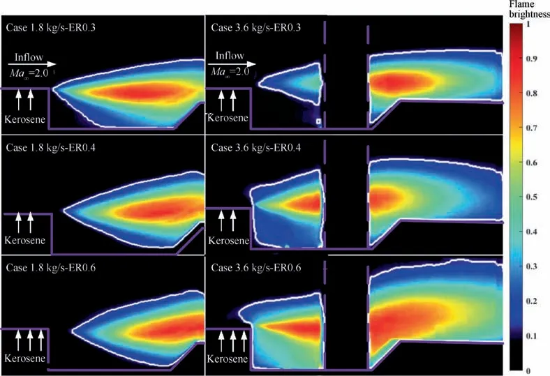
Fig. 2 Average high-speed photographs of flame distribution for different cases.
Fig. 3(a) shows the flamebase oscillations in 1.8 kg/s and 3.6 kg/s cases at ER0.3 and 0.6. The flamebase is defined as the axial position of the flame leading edge.20When the ER is 0.3, the flamebase for 1.8 kg/s case and 3.6 kg/s case can hardly cross the cavity leading edge during the combustion process. It indicates that when the ER is low, the combustion is mainly in the cavity-stabilized mode for both cases. Compared with the case 1.8 kg/s-ER0.3, the oscillation amplitude of the case 3.6 kg/s-ER0.3 is larger, which is also shown in Fig. 3(b). That is because the combustion zone of the case 3.6 kg/s-ER0.3 in Fig.2 is closer to the rearward of the cavity,resulting in a stronger combustion instability.When the ER is 0.6, the flamebase of the 1.8 kg/s case moves downstream along the cavity shear layer obviously, and a stronger flamebase oscillation also occurs. However, the flamebase of the 3.6 kg/s case is located upstream of the cavity and it is difficult to cross the cavity leading edge. It can be concluded that the combustion is mainly in the jet wake mode for 3.6 kg/s case when the equivalence is high.
In order to further study different combustion characteristics for 1.8 kg/s cases and 3.6 kg/s cases, the position changes of the flamebase for all cases during the entire combustion process (about 1 s) are counted, as shown in Fig. 3(b). The horizontal line of each case represents the position range of flamebase oscillation, and the sign in the figure represents the average position of the flamebase. The average position of the flamebase can reflect the overall change of the flamebase during the combustion process. The flamebase can be stabilized in a transverse position in the combustor, where the velocity of the flamebase is equal to the convection velocity of the main stream.21Driscoll and Rasmussen concluded that the propagation speed of flamebase depends on the temperature of the unburned gas upstream of the flamebase, and the unburned gas is heated by the hot gases in the recirculation zone.22As the fuel flow rate increases, the combustion heat release leads to an increase in the temperature of the recirculation zone. However, the increased cold fuel flow rate into the cavity will suppress the temperature rise in the recirculation zone. For the 1.8 kg/s cases, as the ER increases, the average X-axis position of the flamebase tends to move downstream along the shear layer. A possible reason is that the heating effect of the combustion heat release is less than the cooling effect of the cold fuel flow entering the cavity on the recirculation zone,and the temperature of the recirculation zone in the cavity decreases. It results in a decrease in the unburned gas temperature just upstream of the flamebase. The flamebase speed also decreases accordingly, and so the flamebase moves downstream along the cavity shear layer until the flamebase speed equals the convection speed again to achieve a new balance. However, for the 3.6 kg/s cases, as the ER increases, the average X-axis position of the flamebase tends to move upstream along the shear layer. It means that the combustion heat release is intense,and the heating effect of the combustion heat release is larger than the cooling effect of the cold fuel flow entering the cavity on the recirculation zone. Moreover,compared with the flame blowout phenomenon in the case 1.8 kg/s-ER0.6, the stable combustion can be achieved in all 3.6 kg/s cases.It indicates that the 3.6 kg/s facility can broaden the flame rich blowout limit.
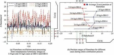
Fig. 3 Flamebase oscillations of all cases (position of cavity leading edge is coordinate origin of flamebase oscillation and oscillating position is dimensionless with injection diameter d).
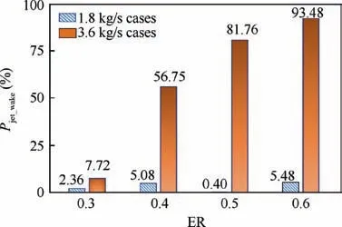
Fig.4 Percentages of combustion in jet-wake-stabilized mode to total combustion time.
Fig. 4 shows the percentages of the combustion in the jetwake-stabilized mode (Pjet_wake) to the total combustion time.20Pjet_wakeof all the 1.8 kg/s cases does not exceed 5.48%,which indicates that the ER has a minor effect on combustion mode transitions. The flame can be stabilized in the cavity shear layer and the downstream expansion wall. However, for the 3.6 kg/s cases, Pjet_wakegradually increases from 7.72% in the case 3.6 kg/s-ER0.3 to 93.48% in the case 3.6 kg/s-ER0.6. This corresponds to the gradual transfer of combustion from the cavity-stabilized mode to the jet-wakestabilized mode. The different changes of Pjet_wakeverify the existence of the scaling effects on combustion modes in the scramjet combustor.
The above-mentioned analysis indicates that as the ER increases, the combustion of the 1.8 kg/s cases can maintain in the cavity-stabilized mode, while the combustion mode of the 3.6 kg/s cases can transfer from the cavity-stabilized mode to the jet-wake-stabilized mode. And the 3.6 kg/s facility can broaden the flame rich blowout limit. To further study the scaling effects of the scramjet combustor, the cavity residence time τr, the ignition delay time τiand the Damkohler number Da are investigated. The Damkohler number Da is a key nondimensional scaling parameter in the research of flame blowout limits and flame stability.22,23It reflects the ratio of flow characteristic time scale to chemical reaction characteristic time scale. In the study, the cavity residence time τris considered as the flow characteristic time and the ignition delay time τiis considered as the chemical reaction characteristic time for the combustion zone, so Da can be expressed as

Based on the detailed kerosene reaction mechanism constructed by Xu et al.24the auto-ignition delay time range of the fuel in the combustor is 50-65 ms when the range of ER is 0.3-0.6 by using CHEMKIN during the initial ignition process. Under the supersonic inflow condition of Mach number 2, the required auto-ignition distance is about 40-52 m, which is much larger than the size of the scramjet combustor.Therefore,the forced ignition must be carried out with the aid of an external ignition source (e.g. spark plug). During the combustion process,the cavity plays an important role in maintaining the stable combustion because the combustion cannot be stabilized without the cavity in our experiments. The shear layer can promote the fuel/air mixing and the exchange of momentum and energy, and the thermal products in the cavity recirculation zone can continuously ignite the fuel entering the shear layer and the cavity.25From the cavity-assisted flame stabilization mechanism, it can be concluded that during the combustion process, the ignition delay time τilargely depends on the temperature of the thermal product in the cavity recirculation zone. Generally speaking, the ignition delay time τiis inversely proportional to the temperature of the thermal product.
The cavity residence time has an important influence on the flame stabilization performance of the cavity. Davis et al.26proposed the concept of cavity residence time τrbased on the Perfectly Stirred Reactor (PSR) model and the conventional cavity (shown in Fig. 5(a)). In the cavity, it can be assumed that the mass flow rate into and out of the cavity is completely determined by the mass flow in the shear layer.They concluded that the cavity residence time can be written as26

Fig. 5 Schematic of cavity for residence time estimation.

where mcavis the mass in the cavity and mcav=ρcavDWL for the conventional cavity. ρcavis the average density of fluid in cavity; D, L and W are the depth, length and width of the cavity, respectively. ˙m is the mass flow rate into the cavity through the shear layer, and ˙m was given by Davis et al. as26

where σ is an empirical constant with a value range of 13-30,determined by the convective Mach number.ρ∞and U∞are the density and velocity of the fluid above the shear layer, respectively. The fluid in the cavity is assumed to be stagnant, and thus one may write:

where Ma∞is the Mach number of the fluid above the shear layer and γ is the specific heat ratio.
For the rear-wall-expansion cavity used in current study(shown in Fig. 5(b)), the mass in the cavity mcavcan be written as

And the mass flow rate into the cavity through the shear layer ˙m is

Based on Eqs. (2)-(6), the cavity residence time for rearwall-expansion cavity used in the current study can be expressed as
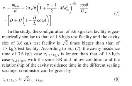
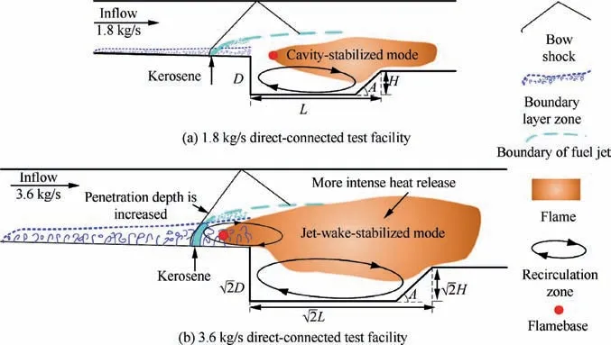
Fig. 6 Schematic of combustion states of cases in 1.8 kg/s and 3.6 kg/s facilities with a high equivalence ratio.
The increase of residence time leads to more favorable flow field conditions for flame holding and spread.17The combustion in the 3.6 kg/s test facility is more intense than that in the 1.8 kg/s test facility. It can be concluded that the thermal product in the cavity recirculation zone of the 3.6 kg/s test facility is higher than that of the 1.8 kg/s test facility. Due to the fact that the ignition delay time τiis inversely proportional to the temperature of the thermal product, one may write:

Based on Eqs. (1), (8) and (9), the Damkohler numbers of the combustor before and after proportional amplification(Da3.6kg/sand Da1.8kg/s) can be written as

Eq. (10) indicates that the combustor of the 3.6 kg/s facility can maintain stable combustion in a wider range of equivalence ratio than the combustor of the 1.8 kg/s facility,which is consistent with the experimental results shown in Table 2.
The schematic of the flow field of different test facilities is given in Fig.6 to further investigate the scaling effects of combustion modes. When the ER is high, compared with the 1.8 kg/s facility, the more intense combustion heat release in the 3.6 kg/s facility leads to transfer from the cavity stabilized flame to the jet-wake-stabilized flame in two ways: first, the more intense heat release can broaden the flame rich blowout limit, which can be confirmed by Eq. (10). And it can restrain the flamebase from moving downstream along the cavity shear layer, which can be confirmed by the analysis in Fig. 3; second, a larger boundary layer separation occurs between the fuel jet and the cavity leading edge because of the heat release.The penetration depth of the jet is further enhanced, so a flow field suitable for combustion is formed upstream of the front edge of the cavity.Finally,combustion occurs upstream of the cavity leading edge and the flamebase propagates upstream to the jet wake, which leads to the transfer from the cavitystabilized mode to the jet-wake-stabilized mode. For the 1.8 kg/s cases, as the ER increases, the flamebase tends to move downstream along the shear layer.Therefore, the flamebase is difficult to propagate to the boundary layer upstream of the cavity to form the jet-wake-stabilized mode, which enables the combustion to be kept in the cavity-stabilized mode.
4. Conclusions
In conclusion, the scaling effects on combustion modes are investigated in a single-side expansion kerosene-fueled scramjet combustor. Two different scale combustors with the mass flow rates of 1.8 kg/s and 3.6 kg/s are compared in the experiment. As the combustor scale changes, the flame distribution and propagation show different characteristics.
Two different combustion stabilized modes are observed in the experiments, i.e., the jet-wake-stabilized mode and the cavity-stabilized mode. For the 1.8 kg/s cases, the ER has a minor effect on combustion mode transitions. As the ER increases, the combustion maintains in the cavity-stabilized mode, and the flamebase moves downstream along the cavity shear layer. When the ER increases to 0.6, the flame blowout occurs. However, as the ER increases, the combustion of the 3.6 kg/s cases gradually transfers from the cavity-stabilized mode to the jet-wake-stabilized mode.And the stable combustion can be achieved in all 3.6 kg/s cases. It is found that the differences in the ignition delay time,the cavity residence time and the Damkohler number caused by different combustor scales play an important role in determining the scaling effects on combustion modes in a single-side expansion kerosenefueled scramjet combustor.
Declaration of Competing Interest
The authors declare that they have no known competing financial interests or personal relationships that could have appeared to influence the work reported in this paper.
Acknowledgements
This work was supported by the National Natural Science Foundation of China (Nos. 11925207, 11902353 and 91741205) and the Foundation of Innovation-oriented Province Construction of Hunan (No. 2019RS2028).
 CHINESE JOURNAL OF AERONAUTICS2021年5期
- CHINESE JOURNAL OF AERONAUTICS的其它文章
- Ferrofluid moving thin films for active flow control
- Preliminary study on heat flux measurement data of TT-0 flight test
- An analysis and enhanced proposal of atmospheric boundary layer wind modelling techniques for automation of air traffic management
- Jet sweeping angle control by fluidic oscillators with master-slave designs
- Hot deformation behavior and microstructure evolution of the laser solid formed TC4 titanium alloy
- Electrochemical trepanning with an auxiliary electrode
