Numerical investigation of full scale coaxial main rotor aerodynamics in hover and vertical descent
Pavel V. MAKEEV, Yuri M. IGNATKIN, Alexander I. SHOMOV
Department of Helicopter Design, Moscow Aviation Institute (National Research University), Moscow 125993, Russia
KEYWORDS Aerodynamic characteristics;Coaxial rotor;Free wake model;Hover and vertical descent;Vortex ring state mode
Abstract The original free vortex wake model was used for numerical investigation.Calculation of the aerodynamic characteristics in hover and vertical descent modes in the range of vertical descent speed of 0-30 m/s including the Vortex Ring State (VRS) area was performed. The calculations were carried out under the condition of variable blade pitch angle values providing a fixed timeaverage thrust value. Visualization data of free vortex wake shapes, flow structures, and velocity fields were obtained and analyzed. The time-dependences of the rotor’s thrust and torque coefficients were obtained and analyzed. The obtained data allows determining the boundaries of the VRS area by various criteria such as rotor thrust and torque pulsations,growth of rotor power consumption relative to the hover,growth of rotor induced velocities relative to the hover,and growth of the required rotor blade pitch angles values. The results of the study are compared with experimental and calculated data of other authors and can significantly supplement the available results of experimental and computational studies in this area.
1. Introduction
The study of the aerodynamic characteristics of a helicopter’s main rotor in vertical and steep descent modes is one of the most important tasks of rotor aerodynamics. This is due to the existence of a special Vortex Ring State(VRS)modes that are directly related to helicopter flight safety. The boundaries of the VRS modes expressed in the coordinates of the horizontal flight and the vertical descent speed (Vx-Vy) are usually included in the helicopter flight manual as a special dangerous area for flights.
The VRS area is determined and analyzed by a number of special features.This is primarily an increase in the power consumed by the rotor with a constant thrust.This is the pulsation of the thrust and torque of the rotor,causing vibrations,shaking,throwing the helicopter on the course,pitch and roll.This is also a special flow picture around the rotor,a point only for the VRS modes.
Studies of the aerodynamic characteristics of a rotor in the VRS modes are carried out in different ways.
Flight tests of VRS modes present significant complexity and potential danger and are therefore limited. However, the flight experiment allows to solve practical problems,for example,to work out the tactics of the pilot’s behavior in the event of a helicopter falling into the VRS mode.An example of such research is shown in the latest work of the Vuichard Recovery Aviation Safety Foundation (VRASF),1presented in 2017.The work of VRASF is of particular interest in its successful attempt to visualize the flow of the rotor in the VRS mode(see Fig. 1(a)).
Model tests of rotors on VRS modes in wind tunnels and on various experimental devices are often associated with great technical difficulties, especially when trying to study largescale models. Let’s mention these difficulties: the difficulty of ensuring low speeds of blowing the rotor in the wind tunnel,the problem of excluding the influence of flow boundaries on the operation of the rotor, the difficulty of ensuring undisturbed flow in the wind tunnel etc.
The first experimental studies of VRS modes for propellers had been conducted in the late 1920 s before the first production helicopters appeared.Glauert2and Lock3are well-known authors focused on this subject.Early results include the work of Drees and Hendal (1951).4This work made it possible, in particular, to obtain a unique quality picture of the smoke visualization of the flow around the rotor in the VRS mode.This illustration(see Fig.1(b))is used as an example in almost all subsequent works connected with the study of VRS modes.During the next 70 years, a number of experimental works have been performed to study the VRS modes of a helicopter rotor.5-15
The specificity of experimental studies of VRS modes is that not the whole set of features related to this phenomenon is usually considered,but individual issues,based on the capabilities of a particular experiment.
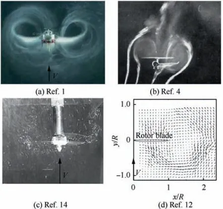
Fig. 1 Results of rotor flow visualizations in VRS mode in several experiments.1,4,12,14
Visualization of the flow of the rotor in the VRS modes by classical methods, such as smoke, is extremely difficult and rarely allows scientists to get a good result. Sometimes they resort to modeling the flow of a rotor in the water tunnel, as in the work of Stack et al. (2005),14where visualization was performed by injecting air into the rotor blade tip vortex cores.The results of this visualization from14are shown in Fig. 1(c).Recently,there has been significant progress in the experimental study of velocity fields around the rotor based on modern Particle Image Velocimetry (PIV) technology. As an example,let’s mention the work of Green et al.(2005).12In their paper,the study of velocity fields around the model(R=7.5 cm)of a three-bladed rotor in the VRS mode in the wind tunnel using PIV technology was carried out. A typical example of the velocity field obtained in Ref. 12 around the rotor in the VRS mode is shown in Fig. 1(d).
Most of the experimental studies of VRS mode focus on the analysis of aerodynamic loads on the rotor since this is of practical interest for helicopter flight. As noted above, the drop in thrust,the increase in torque on the rotor,and their pulsations over time are the main criteria that determine these modes and their danger.Among the works that investigated aerodynamic loads on the rotor in the VRS modes, the following experiments are widely known: Castles and Gray (1951);5Washizu et al. (1966);7Empey and Ormiston (1974);8Xin and Gao(1996);9Caradonna (1999);13Stack et al. (2005).14
Experimental work on the study of VRS modes is characterized by a wide variety of approaches and types of experimental devices. For example, the work by Castles and Gray(1951)5mentioned above was carried out for a 1.8 m rotor in the wind tunnel.The work by Azuma et al.(1966)7was carried out for a rotor with a diameter of 1.1 m, mounted on a movable trolley. The work by Empey and Ormiston (1974)8was carried out for the main and tail rotor models of the AH-1G helicopter on the 1/8 scale also in the wind tunnel. The work by Xin and Gao(1996)9is known by the use of a special rotating stand,where a model of a two-bladed rotor with a diameter of 1.1 m was installed at the end of a rotating beam.The work by Stack et al.(2005)14was performed using a water tank with a model of a three-blade rotor with a radius of 12.7 cm. In Russia, at TsAGI in the 1970s, V. F. Antropov conducted experiments to study the VRS modes on a model of a 5-blade rotor with a radius of 1.32 m, mounted on a movable trolley on rails above the water surface in a 200 m hydro channel.Some results of these studies of Antropov are given in Ref.15. Interpretation of the obtained Antropov’s data later became the basis for a number of approximate computational models of VRS modes. At the same time, TsAGI conducted experimental studies of the model of the coaxial rotor in the wind tunnel in VRS modes using a fixed blade pitch angles approach. The area of the VRS modes was determined by the criterion of rotor thrust drop in comparison with the hovering mode.
It is important to note that the comparison of various results of studies of the aerodynamic characteristics of the rotor in the VRS modes, given in the work by Jonson(2005),16shows their significant differences. Differences in the obtained aerodynamic characteristics lead to different boundaries of the VRS mode area itself. This is obviously due to different rotor geometries and test conditions. Therefore, it is especially important to develop methods that stimulate detailed and comprehensive studies of each specific screw on the vortex ring modes,taking into account the peculiarities of its geometric and kinematic characteristics.
An alternative to experimental research and an addition to it has always been computational research based on mathematical models of varying complexity. Previously, due to the lack of computing resources, not all modes of operation of the helicopter’s rotor were available for creating and applying models with sufficient accuracy.Currently,there are almost no such restrictions.However,it should be noted that the problem of modeling the VRS modes of the helicopter’s main rotor by numerical methods is still the most difficult.This is due,among other things, to the need to model with great accuracy a nonlinear, unsteady vortex wake behind the blades over a large number of revolutions of a rotor.To determine the boundaries of VRS with sufficient accuracy, calculations of several dozen modes may be required. It is clear that those numerical methods that require too many computational resources will not be able to implement such studies in practice.
Numerical methods for modeling aerodynamics, also known as Computational Fluid Dynamics (CFD) methods,are currently represented by a few directions used in the helicopter rotor aerodynamics area.
Vortex methods for calculating the aerodynamic characteristics of a helicopter rotor are widely used.Vortex methods are distinguished by relatively small requirements for computing resources (a personal computer is enough). At the same time,modern free vortex wake models accurately simulate the field of inductive velocities around a rotor. They make it possible to calculate the aerodynamic loads on the rotor:total and distributed along the blade.Modern vortex methods represent the vortex wake behind the rotor blades in an unsteady form.They are successfully used to simulate various modes of operation of helicopter main and tail rotors. Examples of using vortex methods for modeling the VRS modes include Leishman et al. (2002),17Celi and Ribera (2007),18Bailly (2010)19and Shcheglova (2012).20Ref. 17 and Ref. 18 are based on the free-vortex wake model by J. G. Leishman. In Ref. 17, the results of numerical modeling of the aerodynamic characteristics of the main rotors in various operating modes, including the VRS area are presented; a conventional single rotor and two rotors schemes (tandem and tiltrotor) are considered;the coaxial rotor scheme is not considered;the vertical descent of a single rotor with different fixed rate of descent are studied in detail; visualization of the vortex wake shapes were performed; in the VRS modes, significant unsteady pulsations of the rotor thrust and torque were obtained; based on the analysis of these data, the boundaries of the VRS area were determined.In Ref.18,based on the Leishman’s model as a part of the rotor-fuselage dynamic model, a numerical simulation of the vertical descent of a single main rotor helicopter with passage through the VRS area was performed; significant unsteadiness of the rotor flow in the VRS modes and asymmetry of the vortex wake shapes are observed. Ref. 19 is focused on using two computational models developed by Eurocopter and French national aerospace research centre ONERA(Office National d’Etudes et de Recherches Aerospatiales);the research was based on flight test data of the Dauphin helicopter in the VRS modes; it should be noted that the highquality visualization of the rotor flow with the help of airflow lines was performed; obtained data shows extremely complex nature of the rotor flow in the VRS modes.Ref.20 is based on a free vortex wake model developed at TsAGI. A good agreement was obtained with the data of above-mentioned experimental studies of the VRS modes conducted at TsAGI by Antropov.15
In all research described above, performed on the basis of various vortex models, unsteady pulsations of the rotor thrust in the VRS modes were obtained.As noted,pulsations of aerodynamic loads are one of the main criteria for analyzing the VRS area.
In recent years, powerful supercomputers have become commonly used. CFD methods based on the numerical solution of the Navier-Stokes equations using the Finite Volume Method (FVM) and various turbulence models are becoming extremely popular for modeling the aerodynamics of the helicopter rotor. Reynolds-Averaged Navier Stokes equations(RANS)/unsteady RANS approaches are often used to model helicopter rotor aerodynamics. Currently, CFD models based on the FVM method are widely used for modeling the hovering and horizontal flight modes of helicopter rotors but they remain too resource-intensive for modeling the VRS modes,especially in the unsteady settings. Simplified models can be also used to model the VRS modes,where the rotor is replaced by the ‘‘active disk” model, as was done for example at Surmacz (2014)21work. When modeling a rotor with real blades,significantly large computational resources are required. For simplification, a stationary RANS solution can be used, and for axial modes,the features of the axial symmetry of the rotor flow can be also used. For example, Ignatkin et al. (2012)22performed a numerical simulation of the VRS modes under axial descent for a three-bladed MIL Mi-2 helicopter by the RANS method. Time-averaged aerodynamic characteristics of the rotor were obtained.In the work by Mohd and Barakos(2017),23based on the unsteady RANS method use, the axial flow modes of the two-blade rotor from the experimental work by Caradonna,13and the three-blade rotor from the work by Washizu,7including the VRS modes, are investigated. The time dependences of the rotor aerodynamic loads and the visualization of the rotor wake are obtained.
Also, it is necessary to mention the Vorticity Transport Model (VTM) calculation model, set by Brown and Line(2004).24On the basis of this model, numerical studies of the VRS models were performed,presented in the works of Brown et al. (2002),25Ahlin and Brown (2009).26Ref. 25 presents comparative studies of the aerodynamics of a single rotor with two blade twist values 8°and 35°based on the Brown’s VTM24and the Leishman’s free vortex wake models;17the extreme complexity and unsteadiness of the vortex wake and aerodynamic loads pulsations in the VRS modes are shown; it is noted that at the same modes with the same rotor thrust value,the rotor with a large blade twist has a more complex structure of the vortex wake.There are also differences in the VRS area analyzed by the criterion of thrust pulsations. In Ref. 26, an example of calculating a single-bladed rotor based on the VTM method with the high-resolution is given; threedimensional visualization of the rotor wake structure in the VRS are obtained, which are impressive in their complexity and detail.
It is important to note that almost all the experimental and computational studies of the VRS modes described above were performed for the conventional rotor (single main rotor helicopter) or the tiltrotor. However, coaxial counter-rotating rotors are also widely used in helicopters including concepts of high-speed helicopters, developed according to the Advanced Blade Concept (ABC) scheme.27This circumstance increases the relevance of studying the aerodynamics of coaxial propellers, including in the VRS modes.
Experimental studies of the aerodynamics of coaxial rotors consider primarily the modes of hovering and horizontal flight,as in the Refs.28-31There are also works concentrated on modeling of coaxial rotors based on CFD(FVM)and hybrid methods,31,32vortex methods,33-35and by the VTM method.36However,these works also consider only the hovering and horizontal flight modes of the coaxial rotors. But recently there are works that consider not only horizontal flight and hovering for coaxial rotors, but also descent modes and the ground effect during landing. Two such papers have recently been published using CFD methods (with FVM approach). The work by Su et al. (2019)37is concentrated on modeling the landing of a coaxial helicopter on the deck of a ship of various configurations (with an open and closed hangar), the velocity fields around the helicopter and the influence of the environment (ship’s deck, etc.) on the rotor thrust were studied. The work by Kinze et al. (2019)38contains the results of RANSmethod studies of the coaxial rotor at vertical descent, including vortex ring modes, which considers a model of a coaxial four-bladed rotor (with a radius of 0.7 m) of the unmanned aerial vehicle;a preliminary study of the thrust reduction effect at the vertical descent has been made; a conclusion about a smaller thrust reduction and power increase for the coaxial rotor compared to the conventional rotor with the same geometry has been made.
Based on the review of existing works, it can be concluded that there is not enough work dedicated to studies of the aerodynamic characteristics of the coaxial rotors (especially helicopter main rotors) in the VRS modes by both experimental and computational methods.
This article is about numerical studies of the aerodynamic characteristics of the full scale KAMOV Ka-32 coaxial rotor39,40in hovering and vertical descent modes, including the VRS area. The free vortex wake model developed by the authors41is used. Previously, this model was widely used for modeling the VRS modes of the conventional main rotor of a single-rotor helicopter. The results of these studies are presented in the Ref. 42 and Ref. 43.
2. Method and object
2.1. Free wake model
The free wake model of the rotor41developed at the ‘‘Helicopter Design” department of Moscow Aviation Institute is based on the lifting line theory and the blade element theory.Each blade element is modeled by an attached vortex segment located on a quarter of the blade element chord c (see Fig. 2)with the control point in the center of the segment. In each time step Δt a quadrangular contour consisting of vortex segments with a constant circulation Γ,equal to the attached vortex circulation, descends from the blade element. The circulation of the attached vortex changes along the blade radius and depends on the blade azimuthal position. The system of vortex contours creates a free vortex wake in the form of a grid of longitudinal and transverse vortex segments (see Fig. 2). The vortex wake grid is deformed at each calculated step under the influence of external and induced velocity fields.
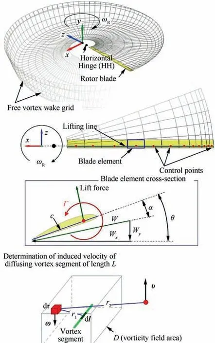
Fig. 2 Free wake model.41
The circulation of the attached vortex of the blade element is calculated with coupling equation:

where CLis the coefficient of the lift force; W is flow velocity.
The coefficients of the lift force CLand the drag force CDof the blade element are determined at the found angle of attack of the blade element α and the total flow velocity W based on airfoil test data in wind tunnel. Determination of the attached vortex circulation is implemented through an iterative method.
Experiments44prove that the distribution of induced velocity close to the vortex axis is different from the analytical expressions of Biot-Savart44(where induced velocity value on the axis equal to infinity) or Rankine44(with a linear law of velocity inside the vortex core). Formulas that describe more accurately the velocity distribution inside the vortex core are also proposed by Scully44and Vatistas44.
The described model uses an approach that allows to determine the vorticity field from the vortex segment and the induced velocity from this vorticity field on the basis of an exact solution of the vortex source diffusion.41
Vorticity of the vortex segment of length L taking into account its diffusion is determined by

where ν is coefficient of kinematic viscosity;r1is distance from the center of the vortex segment;t is diffusion time(see Fig.2).
Knowing the vorticity field, the induced velocity υ of the vortex segment length L can be determined by the equation:

where D is the area where the vorticity field is calculated;dτ is the elementary three-dimensional volume; r2is the distance from the velocity calculation point to the point in the vorticity field.
Integral Eq. (2) does not have an analytical solution in finite limits.The numerical solution of integral Eq.(3)will lead to a large computing resources costs. In order to reduce the calculation time, pre-calculated tables of induced velocities from a normalized vortex segment are used, depending on the length of the segment L, the degree of its diffusion (time t), and the distance r from the segment to the point.
In this model,the rotor blade is modeled as absolutely rigid beam but it can make a flapping motions relative to the rotor hub Horizontal Hinge (HH).
To determine the angle of the blade flapping β at the current calculation step i the Taylor series expansion up to the second derivative is used:

The angular blade flapping velocity is also determined through a Taylor series expansion up to the second derivative.
The angular acceleration of the blade flapping is defined as

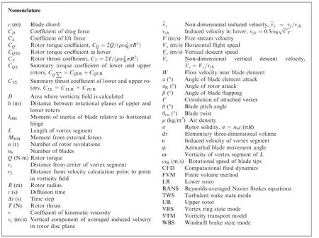
where IHHis the moment of inertia of the blade relative to horizontal hinge; MHHis the moment from external forces (aerodynamic force, gravity, and centrifugal force).
The free wake model developed by the authors has been tested and validated.41The model provide to the determination of the aerodynamic characteristics of both single rotor and various multi-rotor configurations, taking into account the aerodynamic interference.
2.2. Calculation model of coaxial rotor
As an object of research used the coaxial main rotor of the KAMOV Ka-32 helicopter, the characteristics of which are given in Ref. 39 and Ref. 40, and are presented in Table 1.
The scheme of the calculation model of the coaxial rotor is shown in Fig.3.The upper and lower rotor rotates in different directions and each has three blades. The rotational direction of the upper rotor is clockwise (from the top view) and the lower rotor is counterclockwise.
The rotor blade is absolutely rigid, but the calculation model takes into account blade flapping motion relative to the horizontal hinge.
To make the results of the research clearer, the following color data representation system has been chosen, and this has been used in pictures, graphs, and diagrams (see Fig. 3).The data for the upper rotor is blue colored, and the data for the lower rotor is brown colored. The total coaxial rotorcharacteristics are green colored.It is important to note that in the free wake visualization pictures shown below, not all elements of the wake grid are shown, but only the end vortices,as shown in Fig. 3 (blue and brown bold lines).
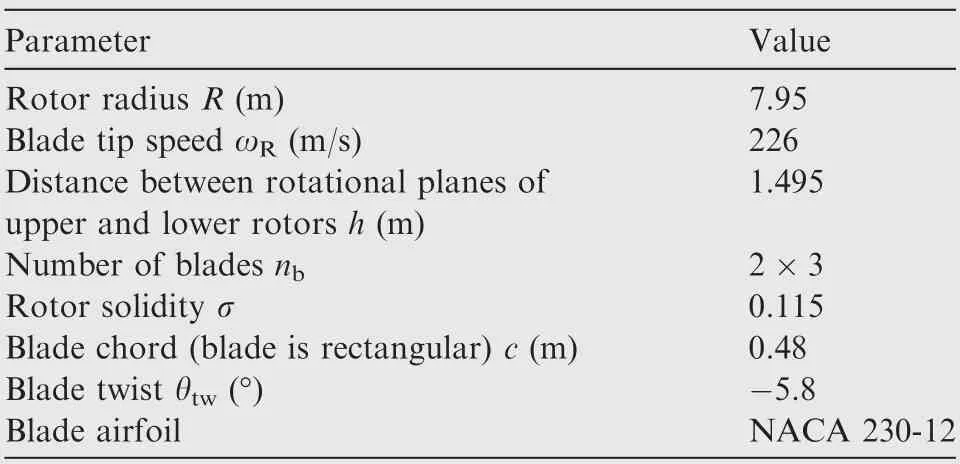
Table 1 Basic characteristics of coaxial rotor under study.39,40
The time step used in the calculations has been corresponding to the rotation of the rotor at an azimuthally angle of 6°.Calculations of each operating mode of the rotor were performed for the number of revolutions of the rotor equal to n=120 r. The time spent on calculating a single regime was about 100 h. We have used a high-performance personal computer equipped with a processor with 8 computing cores (16 threads). Several computers were used simultaneously to perform parallel calculations of several calculation modes.
2.3. Parameters of calculated regimes
When studying the VRS modes of a rotor,two approaches can be used.
In the first approach, the rotor is tested at a fixed blade pitch angles and different free stream velocities. This way is used for almost all experimental studies and most of the numerical simulations. In this case, there is a characteristic decrease in the rotor thrust and unsteady aerodynamic loads pulsations in the VRS area. By studying these and other data,it is possible to analyze the features of rotor aerodynamics in the VRS modes and obtain their boundaries.
In another approach, the average thrust of a rotor has a fixed value, this is achieved by selecting the appropriate blade pitch angles for all considering modes. In this case, the VRS mode’s main feature is increasing the required blade pitch angle and the power consumed. With this approach, it is necessary to perform a large number of calculations to determine the required blade pitch angles, which requires high performance of the applied calculation model.
The free wake model41used in this study has sufficient performance which allowed, as in previous works,42,43to apply the second approach. Therefore, all calculated modes of vertical descent of the coaxial rotor were studied under the condition of constant time-averaged total thrust.
The first part of the paper considers the hovering mode of the coaxial rotor.The calculations of the aerodynamic characteristics at different values of the upper θURand lower θLRrotor blade pitch angles were performed. Selected rotor blade pitch values θURand θLRhave also provided the rotor torque balancing about a vertical rotation axis OY: CQUR=CQLR.
In the second part of the paper, vertical descent modes(αR=90°)are considered in the range of Vy=0-30 m/s.Calculations of the descent modes were performed for constant time-averaged rotor thrust(taking into account possible thrust pulsations). The value of the thrust coefficient was CTΣ≈0.015=const, provided by the selection of the appropriate values of pitch angles θURand θLR.
The obtained diagrams of the upper and lower rotor blade pitch angles are shown in Fig. 4.
At the vertical descent from Vy=0 (hover) to Vy=12 m/s,the coaxial rotor was balanced about the vertical rotary axis OY(CQUR=CQLR).At the vertical descent from Vy=12 m/s to Vy=18 m/s, the condition of CQUR=CQLRwas also done. However, in this range of descent, the same blade pitch angles for both rotors are needed(θUR=θLR).At high speeds of vertical descent(Vy>18 m/s),upper and lower rotors were not balanced to the torque values.This is due to the inability to balance the coaxial rotor close to the autorotation mode. The upper and lower rotor blade pitch angles at Vy>18 m/s were adopted as equal (θUR=θLR).
3. Coaxial rotor aerodynamics analysis in hover
Hovering modes is the base point for analyzing of VRS modes.In addition, the hovering modes considering the coaxial rotor has a number of data presented in works39,40that allowed validation of the applied computational model.
Let’s consider the results of calculations of the coaxial rotor in hover.
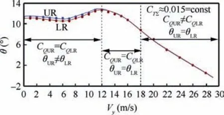
Fig. 4 Upper and lower rotor blade pitch angles used for calculation.
3.1. Aerodynamic characteristics of a coaxial rotor in hover
Fig. 5 shows the calculated hover performance diagram of the coaxial rotor. Fig. 6 shows the comparison of calculated and experimental39diagrams of the Figure of Merit (FoM). There is a satisfactory agreement between the calculation results and the experiment data.
A feature of the coaxial rotor is aerodynamic interference between the upper and the lower rotor. This interaction depends on time and is related to the mutual location of the blades. The result of this aerodynamic interference is the pulsations of aerodynamic loads of rotor, in all operational modes, including hover. Thrust pulsations for a coaxial 8-blade rotor in hover were analyzed by calculation in the works of Deng et al.,31Singh and Friedmann.34Below there are the results of calculating the unsteady pulsations of the rotor thrust and torque coefficients in the hovering mode for the considering coaxial rotor. Fig. 7(a) shows a diagram of the thrust of the coaxial rotor thrust on the number of revolutions of the rotor for the hovering mode(0.015).The dependences of the instantaneous and averaged thrust of the upper and lower rotors separately,as well as their sum,are shown.To analyze a single period of thrust fluctuations,Fig.7(b)shows a fragment of Fig.7(a). Here,for the characteristic points,illustrations of the mutual location of the rotors blades are given. It is clearly seen that the average values of the rotor thrust corresponding to the positions of the upper and lower rotor blades when they are above each other (points ‘‘a” and ‘‘e”), or are equidistant from each other (point ‘‘c”). Rotor thrust is minimal when the blades move from each other (point ‘‘b”) and maximum when the blades move to each other (point ‘‘d”). The amplitude of pulsations of the total thrust is ΔCTΣ/2=4% of the time-averaged thrust value (CTΣ=0.015). The pulsation of the upper rotor thrust is less than that of the lower one. The frequency of thrust pulsations is approximately 27 Hz.

Fig. 5 Rotor performance in hover.
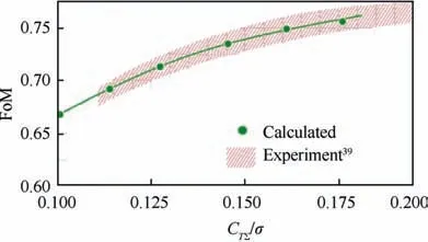
Fig. 6 Figure of Merit in hover.
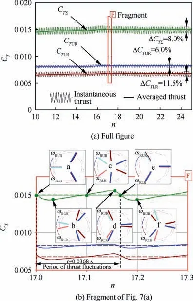
Fig. 7 Instantaneous and averaged thrust coefficient values of coaxial rotor in hover (CTΣ=0.015).
The feature of the coaxial rotor aerodynamics is the difference between a thrust of the upper and lower rotors that observed due to mutual aerodynamic interference. Fig. 8 shows a calculated diagram of the difference between the thrust of the upper and lower rotors depending on the value of CTΣ/σ. The thrust of the lower rotor is taken as 100%.The thrust of the upper rotor is represented in percentage relative to the lower rotor thrust. The results are obtained for a torque-balanced coaxial rotor. It can be seen that the upper rotor has a thrust 15%-22% higher than the lower one. For example, for a value of CTΣ/σ ≈0.132, the upper rotor has a thrust of CTUR≈1.22CTLR, which is in good agreement with the test results presented in Ref. 39.
3.2. Wake structures and flow pictures of coaxial rotor in hover
An important issue in the study of the aerodynamic characteristics of a rotor is the analysis of its wake structures,flow structures, and induced velocity fields. Below we consider and analyze the results of calculations obtained and compared with data from other sources.

Fig. 8 Ratio of upper and lower rotor thrust.
Fig. 9 and Fig. 10 show the results of visualization of the vortex wake of the KAMOV Ka-32 helicopter in hover. In Fig. 10 the tip vortex from the blades of the upper and lower rotor are visualized in a natural way, due to the condensation process in the vortex cores.Here it is seen a clear picture of the vortex visualization behind each of the blades for the azimuthal blade movement angle ψ=0-120°.It can be seen that the trajectories of the tip vortex are initially regular-shaped helical line. However, due to the mutual induced influence of their trajectories quickly begin to deform. Fig. 11 shows a photo of the vortex wake visualization obtained in a flight experiment using smoke40. In general, these results repeat the features noted above, although they are less clear.
Fig. 11 shows the calculated vortex wake shape visualizations for considered coaxial rotor in hover for two values of thrust coefficients CTΣ=0.010 (Fig. 11(a)) and CTΣ=0.015(Fig. 11(b)). Wake shapes are presented in two projections:side and isometric.The characteristic compression of the wake behind the rotor can be seen.There is also the instability of the blade tip vortex trajectories, which is deformed due to mutual wake influence. At the top view, it is clearly shown that the vortex wake is more deformed for a thrust coefficient of CTΣ=0.015 than for CTΣ=0.010.
From the side projection of the vortex wake presented in Fig.11,it is visible that the blade tip vortex of the upper rotor has a 2-3 times greater step of the‘‘helix”than the lower rotor.The value of the‘‘helix”step also increases with the increase in the rotor thrust. This feature of the vortex wake of a coaxial rotor is described in many experimental and computational studies. For example, in the Nagashima and Nakanishi experiment,29Kim and Brown calculations based on the VTM model,36Yana and Rand calculations35and Fernandes research45based on vortex model.
At Fig. 12(a) there are presented results of visualization of the flow around the rotor using airflow lines. In addition, the flow picture contains the induced velocities profiles, constructed for the different distances under the rotor and marked with maximum velocity values. Flow picture and velocity profiles in the Fig.12(a)were constructed for a fixed time moment in the YOZ plane. These results of flow visualization explain the differences between the axial movement speeds of the tip vortex of the upper and lower rotor. It is seen that the blade tip vortex of the upper rotor moves in the flow under significantly higher values of induced velocities than the blade tip vortex of the lower rotor.
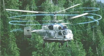
Fig. 9 Natural visualization of vortex wake of Ka-32 coaxial rotor in hover.45

Fig. 10 Smoke visualization of vortex wake of coaxial rotor helicopter while hovering in a flight experiment.40
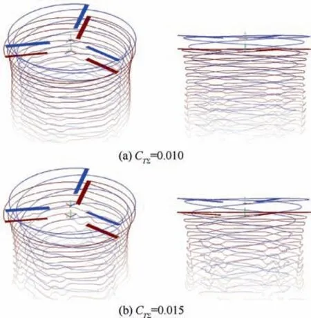
Fig. 11 Calculated visualization of coaxial rotor vortex wake in hover.
As shown in Fig. 12(a) airflow lines can also determine the compression of the flow behind the rotor. Here the flow from the upper rotor is compressed to relative radius r/R ≈0.72,and the flow from the lower rotor to r/R ≈0.87. Due to the compression of the upper rotor flow, the coaxial rotor has an actual disk area greater than that of an equivalent conventional rotor with the same radius and solidity. A well-known result of this feature is higher values of the efficiency (FoM)of the coaxial rotor in the hover.Fig.12(b)has shown the rotational component of induced velocities of the flow behind the coaxial rotor is presented. These velocity profiles are constructed at a distance of r/R=-0.5 (in the B plane, see Fig. 12(a)) from the middle plane of rotation of the rotors.The diagrams illustrate the features of the flow twist characteristic of the coaxial rotor. Earlier in the Ref. 46 the authors noted that the coaxial rotor had a lower rotational component of induced velocities than the equivalent conventional rotor.This is also one of the reasons for the higher efficiency values of the coaxial rotor in hover.
Fig. 13 show graphs with calculated trajectories of the tip vortex of the upper and lower rotor blades for the values of CTΣ=0.010 (Fig. 13(a)) and CTΣ=0.015 (Fig. 13(b)). The comparison with experimental and calculated data of other authors obtained for the same values of the thrust coefficient is given.
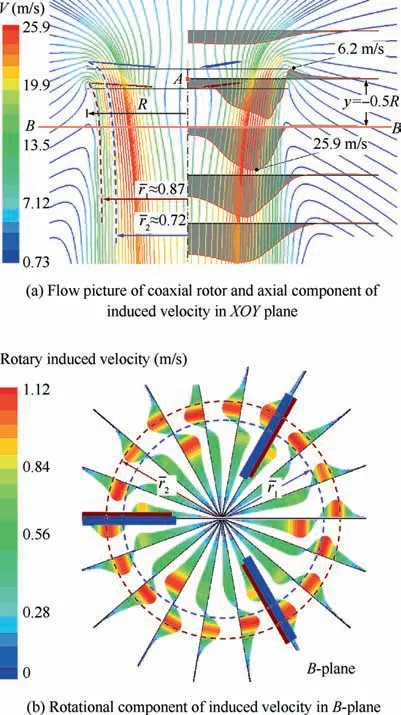
Fig. 12 Flow of coaxial rotor by airflow lines and induced velocity profiles in XOY plane (thrust coefficient is CTΣ=0.015).
For the thrust coefficient CTΣ=0.010 (Fig. 13(a)) the calculated results are compared with data from the experiment of Nagashima and Nakanishi,29Kim and Brown calculation.36The results of Nagashima and Nakanishi,29Kim and Brown36show a significant difference between the axial movement speeds of the blade tip vortex of the upper and lower rotor.In general,there is a satisfactory coincidence of the calculation results with the data provided in the work by Nagashima and Nakanishi,29Kim and Brown.36The existing differences can be attributed to differences in the parameters of the rotors and test conditions.
For CTΣ=0.015 (Fig. 13(b)) the results of calculations of the trajectories of the blade tip vortex are compared with the data on the compression of the flow obtained by analyzing the airflow lines (see Fig. 12). Also calculated data have been compared with the result of analyzing smoke visualization pictures in the flight experiment given in Ref.40(Fig.10).There is no coincidence with the experiment here. However, it should be noted that when analyzing the smoke visualization in the flight experiment,40the vortex trajectories have been obtained only for the azimuthal blade movement angle ψ=0°-120°.
4. Coaxial rotor aerodynamics analysis in vertical descent
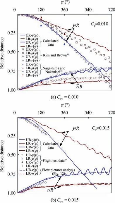
Fig. 13 Comparison of relative tip vortex trajectories of upper and lower rotor with data of Refs. 29, 36, 39.
Below there are the results of the calculations of the coaxial rotor aerodynamic characteristics of the Ka-32 helicopter39,40in vertical descent modes (αR=90°). Descent speed values of Vy=1-30 m/s with a step of 1-2 m/s were considered.Calculations of each mode performed with a blade pitch angles of the upper and lower rotors are presented in Fig. 4. These values of the blade pitch angles have provided a constant value of time-averaged thrust coefficient of coaxial rotor CTΣ=0.015 (with taking into account of possible thrust pulsations). In total, 25 calculation modes were calculated, each for n=120 r.
It is known,that for the steep descent modes,we can distinguish a number of characteristic modes. Among these modes there are the upper border of the VRS area, the ‘‘peak” of VRS, an area of the ‘‘Turbulent Wake State” (TWS) modes,‘‘autorotation” mode, and the ‘‘Windmill Brake State”(WBS)modes.Each of these modes has its own features.There are fully presented and analyzed the results for 5 specific modes. The results of other calculated modes appear in the final results at the end.
4.1.Wake structures analysis of coaxial rotor in vertical descent
Fig. 14 shows the results of visualization of the vortex wake shapes of the coaxial rotor on the most characteristic modes.Shapes of the rotor wake on the descent modes, especially in the VRS are characterized by great complexity and unsteadiness. At Fig. 14, the wake shapes of each mode are given for the moment of time corresponding to the thrust value equal to the average value,which is CTΣ=0.015.Note that the vortex wake is not shown as a full calculation grid,but only as the trajectories of the tip vortex of each blade. Thus the picture becomes clearer for visual analysis.
Fig.14(a)shows the hovering mode,which was discussed in detail in Section 3.2,and is presented here for ease of comparative analysis.
Fig. 14(b) shows a vortex wake for the vertical descent mode with a speed of Vy=7 m/s. At this descent speed rotor is entering the area of the VRS. It can be seen that the vortex wake collapses into a specific toroidal body - a vortex ring.This vortex ring is located at some distance under the rotor.As the rate of descent increases, the vortex wake moves upward.
At the most intensive VRS modes, the vortex wake is located near the rotational plane of the rotor. An example of this is shown on Fig. 14(c) and corresponds to the descent speed of Vy=12 m/s.It can be seen that the vortex ring loses its axial symmetry.This loss of symmetry is the most specific of a coaxial rotor. This is connected with the existence of the coaxial rotor specific azimuths, where the blades of the upper and lower rotor are meeting. In the Ref. 42 performed by the authors for a single rotor,such effect of loss of axial symmetry of the vortex wake in the VRS has not been observed.
When the speed increases further, the vortex wake moves higher (see Fig. 14(d)). There is ‘‘turbulent wake state” modes area characterized by high instability and pulsations of the flow (vortex wake) behind the rotor. An example of these modes is Vy=18 m/s and is shown on Fig. 14(d). Here the axial asymmetry of the wake is higher and better visible.
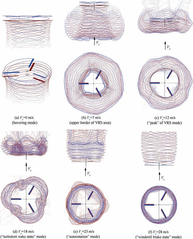
Fig. 14 Free vortex wake shapes of coaxial rotor for different vertical descent rates (αR=90°).
The ‘‘autorotation” mode for the studied coaxial rotor,when the total torque of the rotor is 0 is observed when the vertical descent speed is Vy=23 m/s(see Fig.14(e)).The axial symmetry of the vortex wake is restored, and its shape becomes more stable.
On ‘‘windmill brake state” modes, for example at Vy=28 m/s (see Fig. 14(f)), blade tip vortex trajectories are close to helical lines again, as in the hovering mode.
When analyzing the vortex wake visualization pictures, the complexity and unsteadiness of its shape were noted in the VRS, including ‘‘turbulent wake state” modes. Also the observed effect of significant axial asymmetry of the vortex wake is of great interest. And this is obviously a feature of the coaxial rotor. Fig.15 shows the shapes of the vortex wake for Vy=12 m/s for different time moments(numbers of revolutions of a rotor). When analyzing changes in the shape of a wake over time, the features described above are particularly visible.It is important because the unsteady effects of the vortex wake in the VRS modes are directly related to the rotor aerodynamic loads pulsations. In turn, the pulsations of aerodynamic characteristics are one of the main features of the VRS modes.
4.2.Flow analysis around coaxial rotor in vertical descent modes
Fig. 16 shows the results of visualization of the flow around a rotor, corresponding to the vortex wake visualization pictures shown in Fig. 15. Velocity fields and airflow lines have been constructed for each of the calculated modes in the XOY plane for a fixed moment of time.The presented pictures of flow are constructed for the moments of time corresponding to the rotor thrust value CTΣ=0.015 (like a wake picture at the Fig. 14).
Fig. 16(b) presents a vertical descent with a speed of Vy=7 m/s. The characteristic ‘‘air body” formation around the rotor is observed. This process is also observed in experiments (see Fig. 1). The ‘‘air body” is formed by a boundary where the induced flow from the rotor becomes equal to the free stream. Before the ‘‘air body” there is a zone of braking with zero flow velocities.Inside the‘‘air body”there is a circulation flow with a clearly defined core.This core is the core of a toroidal vortex ring formed by a rotor wake, as described above (see Fig. 14(b)). At the same time, it can be seen that the flow next to the rotor is similar to its structure in hover.It should be noted that the size of the ‘‘air body” is almost 2.5 size of the rotor diameter. This fact enforces special requirements on the wind tunnel size during experiments in the VRS modes.
As the rate of descent increases the ‘‘air body” moves upward. At the descent speed of Vy=12 m/s (Fig. 16(c)) the‘‘air body” is located near the rotation plane of the rotor. In this case, the ‘‘air body” is significantly smaller than at Vy=7 m/s, especially in height. The circulation flow inside the ‘‘air body” becomes more intense. It is important that the ‘‘air body” in these modes is unstable in time. Following the vortex wake of the rotor,the‘‘air body”constantly makes vertical movements and, in addition, changes its shape. This phenomenon is the cause of pulsations of aerodynamic loads on the rotor, which will be described below.
In the‘‘turbulent wake state”mode at Vy=18 m/s(Fig.16(d))the lower boundary of the‘‘air body” is located almost in the plane of rotation of the rotor. In these modes, the upper part of the vortex ring begins to blur, and the flow behind the rotor is particularly unstable.
The ‘‘autorotation” mode for this case occurs when Vy=23 m/s (see Fig. 16(e)). In this case, the flow is slowed down in the plane of rotation of the rotors(except for the central part of a rotor). The ‘‘air body” around the rotor is no longer observed.
Fig.16(f)shows the‘‘windmill brake state”mode,in which the flow moves through the rotational plane.However the flow is significantly slowed down, and the flow energy is partially converted into the rotation of the rotor.
4.3. Aerodynamic characteristics of coaxial rotor analysis in vertical descent modes
Fig.17 presents diagrams of the thrust and torque coefficients of the coaxial rotor versus the time (number of revolutions of the rotor). A diagram contains the data for a number of characteristic modes under study (see Figs. 14 and 16). The values of the thrust and torque coefficients for the upper and lower rotor and their summary values are shown. The coefficients for the lower and upper rotors are represented by averaged values curves (instantaneous values are not shown). The total thrust and torque values are shown as both averaged values curves and instantaneous values curves with high-frequency pulsations (they merge into solid areas in Fig. 17).
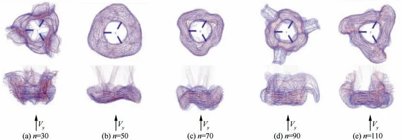
Fig.15 Free vortex wake shapes of coaxial rotor at VRS mode(Vy=12 m/s)for different moments in time(number of revolutions of a rotor).
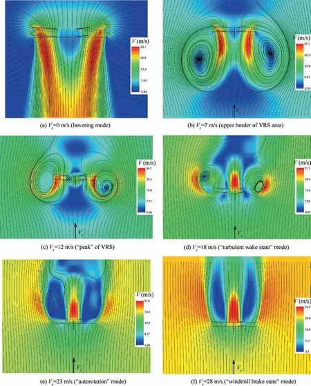
Fig. 16 Flow around coaxial rotor for different vertical descent rates (αR=90°).
The thrust and torque diagrams for hovering mode are shown on Fig. 17(a) were analyzed earlier in Section 3.1.
Fig. 17(b) shows diagrams for the speed of descent Vy=7 m/s.The diagrams show the differences in the averaged thrust and torque values from their values in hovering mode.These pulsations with a very long period are associated with changes in the shape and position of the vortex wake over time. At this speed of descent the rotor enters into the VRS area.Based on a comprehensive analysis of rotor aerodynamic characteristics, it is recognized that this mode is close to the upper border of VRS.But the vortex wake is located at a long distance from the rotor rotational plane.That’s why the thrust and torque pulsations are still not too significant.From Fig.17(a) it is also seen that the torque coefficient decreases relative to its value at hovering mode by 8%.This indicates a decrease in the power consumption of the rotor. The descent speed at which this phenomenon is observed depends on the rotor disc loading. A similar result (adjusted for a smaller amount of rotor disc loading) was obtained in the flight tests on the Mi-8 helicopter, which has been mentioned in Ref. 40.
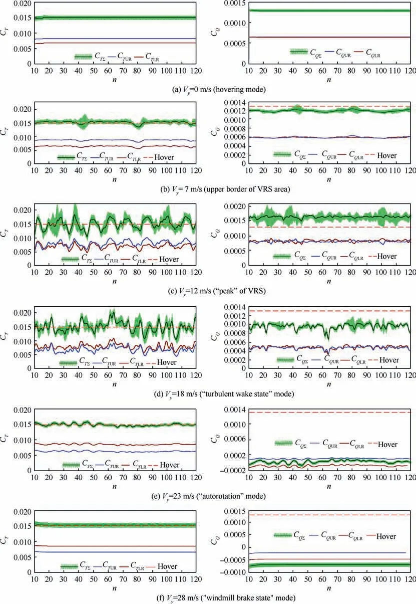
Fig.17 Diagrams of dependence of thrust and torque coefficients vs.number of revolutions of rotor for different vertical descent speed(αR=90°).
At a speed of Vy=12 m/s (Fig. 17(c)) the rotor torque value increases compared to hovering mode by 22%. This is the maximum obtained power growth value of all the considered modes of descent. That’s why this mode is called the‘‘peak” mode of VRS. The observed pulsations of the rotor thrust at this mode are significant; their amplitude reaches 35% of the average (CTΣ=0.015) value. The average thrust pulsations are quite regular; their period is approximately 10-15 r of the rotor.Similar results were obtained in the work of Stack et al.14As it has been mentioned above,these periodic pulsations of the averaged thrust are associated with periodic large changes in the shape of the vortex wake and its movements up and down relative to the plane of rotation of the rotor.
High-frequency pulsations of instantaneous thrust and torque in the VRS area (presented of light green solid areas in Fig. 17) are more significant compare to hovering mode.
When hovering, pulsations of the instantaneous thrust and torque are regular and are related to the interference of the upper and lower rotor blades (see Fig. 17(a) and Section 3.1).In VRS modes,pulsations of the instantaneous thrust and torque are significantly amplified and become irregular with a time-varying amplitude. From the analysis of the given vortex wake shapes (see Fig. 15) and velocity fields, we can conclude that the cause of such aperiodic pulsations is the unsteady shape of the vortex wake and its induced velocity fields near the rotational planes of the rotor blades. The analysis shows that sometimes the vortex wake and the velocity field have a significant axial asymmetry. Thus, in some cases, pulsations associated with the rotation of the blade in a complex variable induced velocity fields are added to the thrust pulsations caused by the interference of the blades. As a result, in these modes, the total pulsations of instantaneous thrust can have much larger amplitude than in hovering or ‘‘windmill brake state” modes.
An important conclusion can be made from the averaged thrust curves of the upper and lower rotor (Fig. 17(c)). It can be seen that the thrust of the upper and lower rotor increases or decreases simultaneously. This means that the described phenomena have the same effect on both rotors at once.
At the ‘‘turbulent wake state” mode (Vy=18 m/s, see Fig. 17(d)) significantly pulsations in the aerodynamic characteristics of the rotor are also observed.The average thrust pulsations become irregular. It is difficult to distinguish any period of pulsation here. The average torque value of this mode is lower than that in hovering mode, so this mode is not included in the area of VRS modes according to this criterion.Shown in Fig.17(d)instantaneous pulsations of the total thrust and torque of the rotor are special interest because of irregularity of their amplitude. We can see areas (for different values of n) with the high differences in the amplitude of instantaneous pulsations.
On Fig.17(e)there is presented the rotor thrust and torque coefficients diagram for ‘‘autorotation” mode (Vy=23 m/s).The total rotor torque coefficient is 0. In this case, the upper and lower rotor cannot be balanced on the torque. Small pulsations of the average thrust are observed. The amplitude of the instantaneous total thrust of the rotor becomes almost constant in time, as in the hovering mode.
Fig.17(f)shows the‘‘windmill brake state”mode.The total torque coefficient is becoming negative here. This indicates that the rotor does not consume power, but produces it under the influence of the free stream. There are no fluctuations in the average thrust or torque.Instantaneous pulsations are regular and similar to hovering mode.
5.Summary diagrams of aerodynamic characteristics of coaxial rotor in hover and vertical descent
Let’s consider the final diagrams of calculated coaxial rotor aerodynamic characteristics in hovering and vertical descent modes. The analysis of the diagrams below makes it possible to determine the area of the VRS modes of the coaxial rotor using various criteria.
Fig. 18 shows diagrams of the dependence of the timeaveraged thrust and torque coefficients on the speed of vertical descent. Fig. 18 includes the total thrust and torque of the coaxial rotor and the thrust and torque of the upper and lower rotors separately.
In Section 3.1, it was shown that in hovering mode the upper rotor has higher thrust values than the lower rotor(for the equal rotor’s torque). For example, the upper rotor thrust was 22%higher for CTΣ=0.015.From Fig.18(a)it follows that at a certain speed of descent, the distribution of thrust between the rotors changes its sign. As a result, the‘‘windmill brake state” mode (for example, Vy=28 m/s) has 22% more thrust of the lower rotor. Meanwhile as it follows from Fig. 18(a), there is a mode of operation of the coaxial rotor where the thrust of the upper and lower rotors are equal.In considering case, this is the speed of vertical descent of Vy=14 m/s. At this point, the mutual interference of the rotors on each other is balanced and then changes its sign.
Fig.18(b)shows the time-averaged torque coefficient versus the descent speed. As it has been noted earlier, the coaxial rotor was balanced on torque due to the selection of blade pitch angles up to the descent speed of Vy=18 m/s. At low speeds of descent (Vy=5-7 m/s), the total coaxial rotor torque coefficient is reduced by 8%relative to the hovering mode.Maximum torque values are observed in the ‘‘peak” modes of the VRS at Vy=11-12 m/s. Here, the rotor torque increases by 22%. The growth of the rotor torque relative to the hovering mode, that is, the growth of the rotor consumed power, is one of the main criteria of the VRS area boundaries. Data of Fig. 18(b) shows that ‘‘autorotation” mode, arise first on the lower rotor (time-averaged CQLR=0, Vy≈22 m/s) and then on the upper rotor (averaged CQUR=0, Vy≈24 m/s). The autorotation mode of the coaxial rotor corresponding with zero value of the total torque (time-averaged CQΣ=0) is observed at the vertical descent speed is Vy≈23 m/s.
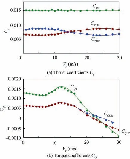
Fig. 18 Dependences of time-averaged values of thrust and torque coefficients of coaxial rotor vs. speed of vertical descent.
It may be noted that the curve of total torque coefficient values CQΣ(Fig. 18(b)) is consistent with the curve of the required values of the blade pitch angles θ (Fig. 4). To maintain a constant rotor thrust in the VRS area (Vy=8-15 m/s), it is necessary to increase the rotor power. That is why,the value of the rotor torque increases in these regimes. This in turn requires increasing of the blade pitch angles. Conversely, at high speeds of descent (Vy>16 m/s), when the rotor begins to use the incoming flow energy for its rotation,the required blade pitch angles rapidly fall. For example,hovering mode requires blade pitch angle of 11.5° but the autorotation mode (Vy=23 m/s) requires of 4° (Fig. 4).
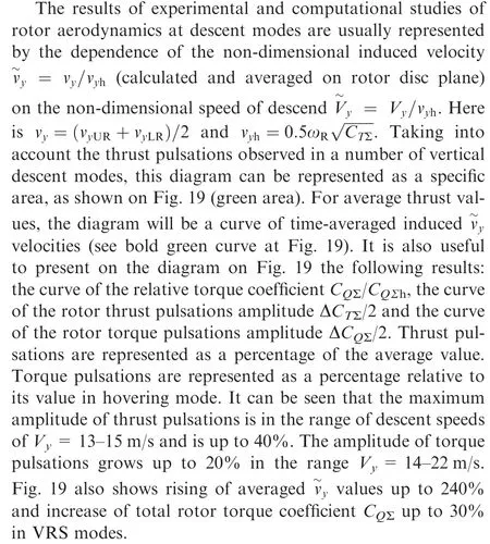
The presented universal diagram contains almost the whole set of rotor’s aerodynamic characteristics. Having formed the criteria for evaluating these characteristics, it is possible to determine the boundaries of the VRS mode area. Usually,there are several criteria that have their own boundary: thrust pulsations amplitude, torque pulsations amplitude, the increase in power (the rotor torque increase) consumed by the rotor, the increase in the average induced velocities and the increase in the required blade pitch angles (for constant rotor thrust).
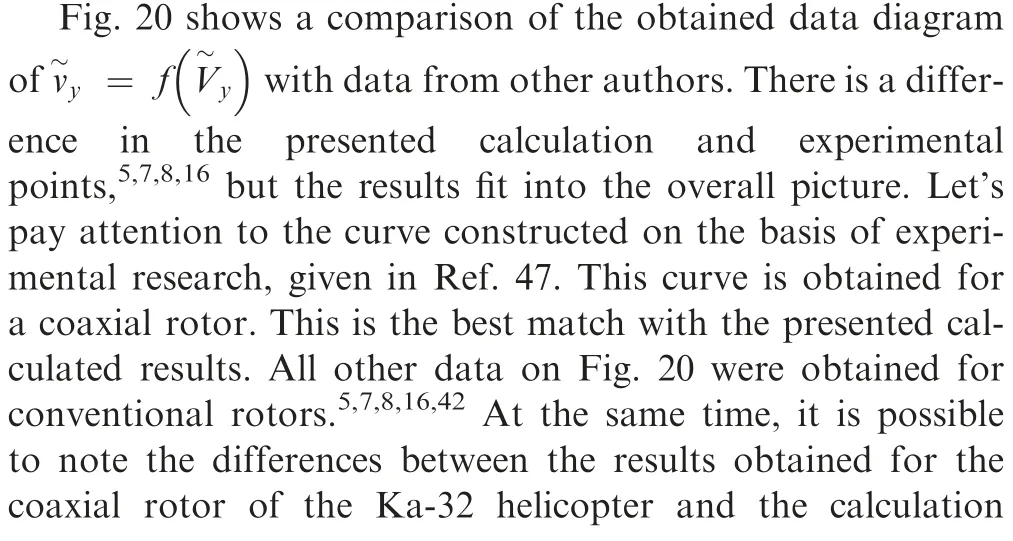
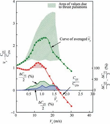
Fig.19 Total diagrams of aerodynamic characteristics of coaxial rotor in hovering and vertical descent modes.

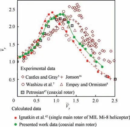
Fig. 20 Comparison of dependencies of =f() obtained in calculations and experiments.
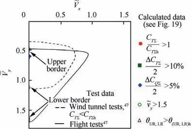
Fig.21 Comparison of calculated and experimental47 borders of VRS modes area of coaxial rotor.
Fig.21 shows the borders of the VRS area in dimensionless velocity coordinates given in Ref. 47. These results were obtained on the basis of experimental and flight tests of the coaxial main rotors.47The first area was determined basing on the analysis of experimental studies of the coaxial rotor model in VRS modes in the wind tunnel at a fixed rotor blade pitch angle. In this case, the area of the VRS was constructed according to the criterion of reducing the rotor thrust relative to the hovering mode. According to this criterion, the VRS borders are in the range of dimensionless descent rates of=0.35-1.13.This result is close to the VRS borders defined by the criterion of increasing the calculated relative rotor torque coefficient CQΣ/CQΣh>1 (see Fig. 19) and growth of the required blade pitch angles θ(UR,LR)>θ(UR,LR)h(see Fig. 4).The second border of the VRS mode is based on the analysis of helicopter behavior in the flight experiment.47Here the VRS area is larger and lies in the range of dimensionless descent rates of=0.45-1.70.These data coincide with the criterion obtained from the analysis of the calculated rotor thrust pulsation amplitude value ΔCTΣ/2 >10%; amplitude of torque pulsations ΔCQΣ/2 >5% and increase in time-averaged induced velocity values relative to the hovering mode>1.5 (see Fig. 19).
6. Conclusions
(1) On the basis of a free wake model developed at Moscow Aviation Institute,numerical studies of the aerodynamic characteristics of the six-blade coaxial main rotor of the Ka-32 helicopter were performed.The hovering and vertical descent modes at the range of Vy=1-30 m/s,including the area of the VRS modes, were considered.All calculations have been performed at a constant time-averaged total thrust coefficient CTΣ=0.015, taking into account thrust pulsations.For this purpose,the corresponding angles of the upper and lower rotor blades pitch angle were selected. In the descent speed range of Vy=0-18 m/s, the coaxial rotor was also balanced by the torque value (CQUR=CQLR).
(2) For the hovering mode,the rotor performance and FoM diagrams are obtained.FoM diagrams have good agreements with experimental data of Bourtsev et al.39The ratio of thrust between the upper and lower rotors has been analyzed. For CTΣ=0.015 found that the upper rotor thrust exceeds the lower rotor thrust to 22%,which is confirmed by data of the flight experiment of Bourtsev et al.39The analysis of the relationship between thrust and torque pulsations and the aerodynamic interaction of the upper and lower rotor blades is presented.The relationship between instantaneous thrust and torque values and relative position of the upper and lower rotor blades during rotation of the coaxial rotor is shown.The results obtained are consistent with the computational data demonstrated in the work of Singh and Friedmann34for an eight-blade coaxial rotor.
(3) For the values of the thrust coefficient CTΣ=0.010 and CTΣ=0.015, examples of calculating tip vortex trajectories are given and the flow behind the rotor is analyzed. A satisfactory match of vortex wake geometry was obtained with the results of experiments29and calculations.36
(4) The aerodynamic characteristics of the coaxial rotor are obtained for the considered vertical descent modes, the flow around the rotor has been investigated, and the shape of the vortex wake is presented.
(5) The dependence of the thrust and torque of the upper and lower rotors, as well as their total values on the number of revolutions of the rotor, is presented. The relationship between the features of the rotor flow and its aerodynamic characteristics in different vertical descent modes is shown. The pulsations of the rotor thrust are analyzed.It is shown that in the VRS and‘‘turbulent wake state”modes,in contrast to hovering or‘‘windmill brake state” modes, the pulsations of the aerodynamic characteristics of the rotor are essentially unsteady with a non-constant period and amplitude of oscillations.It is established that this is due to the complex and unsteady shape of the vortex wake of the coaxial rotor in these modes, in particular, with the axial asymmetry of the vortex wake.
(6) It is determined that relative to hovering mode on the VRS modes are observed: total rotor thrust pulsations amplitude up to 40%; total rotor torque pulsations amplitude up to 20%; rising of averaged induced velocity values up to 240%; increase of total rotor torque coefficient up to 30%.
(7) A diagram of non-dimensional induced velocity values depending on the non-dimensional rate of descent is obtained. A satisfactory qualitative and quantitative agreement data obtained with the data of other author’s researches are shown.5,7,8,16A good agreement between the calculation results and the data of experimental studies of the coaxial rotor46was obtained.The comparisons of obtained coaxial rotor data and previous data40of the single rotor make it possible to conclude a shift of the VRS modes of the coaxial rotor in the direction of large values speed of descent. This can be caused by specific features of the coaxial rotor itself, as shown in Kinzel et al.,38and confirms the need to study the VRS modes for each specific helicopter rotor,taking into account its features.
(8) The results obtained allow us to determine the border of the VRS modes area at vertical descent by various criteria.Obtained VRS borders by using of these criteria are:
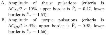
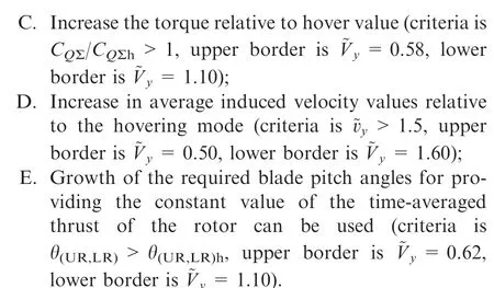
The obtained VRS borders for vertical descent modes coincide well with the boundaries determined on the basis of wind tunnel experiments and flight tests of the coaxial rotor.46
(9) The strengths of the applied model can be attributed to its high performance. This fact is of particular importance for the considered VRS modes. To make a full aerodynamic analysis it must be calculated a very large number of the rotor revolutions. At the same time the applied model is not fully able to take into account and study some effects,such as the pressure distribution on the surface of the blades, or the high-accurate simulation of the blade-vortex interactions. However, the applied free wake model has sufficient capabilities to conduct a comprehensive cross analysis of the aerodynamic characteristics and the physical picture of the rotor flow on the VRS modes.
(10) The results of research on the aerodynamics of a coaxial rotor in vertical descent modes presented can significantly supplement the available data of experimental and computational studies.
(11) In future we are getting to provide a numerical study of the steep descent modes of the coaxial rotor with different angles of a rotor attack αR=80°-30°, which will allow us to obtain and analyze the full area of the VRS modes in the flight speed coordinates ~Vx-~Vy.
Declaration of Competing Interest
The authors declare that they have no known competing financial interests or personal relationships that could have appeared to influence the work reported in this paper.
 CHINESE JOURNAL OF AERONAUTICS2021年5期
- CHINESE JOURNAL OF AERONAUTICS的其它文章
- Ferrofluid moving thin films for active flow control
- Preliminary study on heat flux measurement data of TT-0 flight test
- An analysis and enhanced proposal of atmospheric boundary layer wind modelling techniques for automation of air traffic management
- Jet sweeping angle control by fluidic oscillators with master-slave designs
- Hot deformation behavior and microstructure evolution of the laser solid formed TC4 titanium alloy
- Electrochemical trepanning with an auxiliary electrode
