Influence of shock wave impinging region on supersonic film cooling
Xioki SUN, Hng NI, Wei PENG,*, Peixue JIANG, Yinhi ZHU
a Institute of Nuclear and New Energy Technology, Collaborative Innovation Center of Advanced Nuclear Energy Technology,Key Laboratory of Advanced Reactor Engineering and Safety of Ministry of Education, Tsinghua University, Beijing 100084, China
b China Institute of Nuclear Industry Strategy, 100048, China
c Department of Energy and Power Engineering, Key Laboratory for Thermal Science and Power Engineering of Ministry of Education, Tsinghua University, Beijing 100084, China
KEYWORDS Film cooling;Impinging region;Mach number;Shock wave;Supersonic flow
Abstract Shock waves can significantly affect the film cooling for supersonic flow and shock waves may have different influence when impinging in different regions. The present study numerically compared the results of shock wave impinging in three different regions and analyzed the effect of impinging region. The shock wave generators were located at x/s=5, 25, 45 with 4°, 7° and 10° shock wave incidence. The mainstream Mach number was 3.2 and the coolant Mach number was 1.2 or 1.5. The numerical results illustrated that the shock wave impinged in the further upstream region led to a larger high-pressure region and a larger vortex in the boundary layer.Moreover, placing the shock wave generator upstream resulted in the lower mass fraction of coolant in the downstream region.The velocity in the upstream part of the cooling layer was lower than the midstream and downstream part, which resulted in the less ability to resist the shock wave impingement. Therefore, the upstream impingement deteriorated the cooling performance to a greater extent.The study also manifested that the stronger shock wave had a larger effect on supersonic film cooling. Increasing the coolant inlet Mach number can increase the blowing ratio and reduce the mixing, which was of benefit to improve cooling effect.
1. Introduction
Film cooling can reduce heat load and avoid overheating as a promising cooling method, which introduces cooling gas through holes to protect cooling hole exit and further downstream.1,2Film cooling has a good application prospect in gas turbines.3-8The factors influencing film cooling include geometric parameters such as the shape of the film hole and flow parameters such as the blowing ratio, Reynolds numbers.9-14Film cooling has many advantages, such as adding engine thrust,preventing the separation of boundary layer and reducing skin friction.15,16When the mainstream is supersonic,the system is called supersonic film cooling. For the hot components whether in scramjets or in the hypersonic vehicles and rockets,17-22supersonic film cooling is a key cooling method for consideration.
There is a big difference between supersonic film cooling and subsonic film cooling. The shock wave always occurs in the supersonic flow field, which significantly affects the flow and heat transfer characteristics.
Zuo et al.23used gaseous hydrocarbon fuel as coolant to study the effect of cracking reaction on supersonic film cooling. Their study confirmed that cracking reaction was beneficial to supersonic film cooling, which absorbed heat and reduced the wall temperature. The study of Keller and Kloker24used direct numerical simulations and found wallnormal heat conduction was strengthened and the cooling film was heated more quickly in case of turbulence. Song and Shen25,26experimentally studied backward-facing slot supersonic film cooling by schlieren and shadowgraph visualizations. Their experiments gave a verification that feeding pressure and Mach number had a great impact on the flow field. The experimental investigation of Alzner and Zakkay27compared flows with and without shock waves and showed the phenomena of reversed flow and the boundary layer separation caused by a sharp unfavorable pressure gradient with shock wave impingement. George et al.28used a simple twodimensional flow configuration to do an experimental study.Their results showed that it was the most effective when achieving a match between the coolant pressure and the local boundary layer edge pressure.The experimental and numerical research of Kamath et al.29confirmed that the heat transfer was enhanced by increasing the turbulence on account of shock wave incidence. Juhany et al.30,31investigated the interaction between the cooling film and a two-dimensional shock wave.Their experimental results for the adiabatic wall temperature showed that the lower cooling effectiveness was a consequence of the shock wave impingement and that higher coolant Mach numbers appeared to delay separation, which led to better cooling. Hyde et al.32experimentally investigated the flow profiles for an impinging shock wave.Their study concluded that the impinging shock wave strongly affected the mean-flow profiles by both adding turbulence and thickening the shear layer. Souverein and Debieve33employed an array of vortex generators jets to control a Mach number 2.1 impinging shock wave boundary layer interaction.They reported significant reduction in the separation bubble length and an overall increase in the boundary layer profile fullness. The experimental results of Kanda et al.34,35showed that the deteriorated cooling performance in the impinging region was not caused by mixing of the coolant with the mainstream, but rather by the decreased local Mach number. However, the analysis by Konopka et al.36,37using Large-Eddy Simulations(LES) concluded that the shock wave impingement in the potential-core region changed the laminar boundary layer to turbulence immediately and thus increased mixing degree.Peng and Jiang38numerically investigated shock wave/cooling film interaction and explained the interaction mechanism,mainly because the local Mach number was reduced by the increased local pressure and the strong shock wave increased the mixing significantly. To weaken the shock wave impingement, Peng and Jiang39developed a slotted wall with a cavity with their numerical results showing that the slotted wall structure is beneficial to film cooling. Peng et al.40investigated the three-dimensional effect of shock wave on film cooling, with the result showing that a secondary flow in the boundary layer reduced the film cooling effectiveness.
Generally,the shock wave/cooling film interaction is closely related to the velocity distribution in the boundary layer. In Fig. 1, depending on the velocity distribution, the flow field can be classified as three flow regions, the upstream region,the midstream region and the downstream region. Of which,the region close to the slot and before the mixing layer almost reached the wall is the upstream region, the region where the mixing layer merges with the mainstream boundary layer is the midstream region, and the region where the mainstream and coolant stream still mix, but the time-averaged velocity profiles already possess the shape like a fully developed boundary layer is the downstream region.
For the velocity distribution in different regions are quite different, the shock wave impinging region would have different influence. In general, most previous studies only investigated the cases when impinging in the upstream region of the boundary layer, while in the actual situation, the shock wave may impinge in all supersonic regions, such as the midstream region and the downstream region. However, there has been only few research considering the difference between the three regions. The present study mainly focused on the influence of shock wave impinging region on supersonic film cooling. The influence of the shock wave intensity and the coolant Mach number were also investigated.
2. Model
2.1. Numerical model

Fig. 1 Three flow regions divided in flow field.

Fig. 2 Film cooling model.
Fig.2 showed the schematic diagram of the model.The supersonic high temperature mainstream and the cooling stream entered the section in parallel from their respective inlets.The x direction was parallel to the flow direction, and the y direction was perpendicular to the wall. The mainstream entrance was at x=-0.05 m, the outlet was at x=0.5 m and the height was 0.03 m. The coolant inlet was s=4 mm high and the separating lip was t=0.5 mm thick. A shock wave generator was used, as shown in Fig. 3, which is 20 mm long and the height varied with the angle. The supersonic flow impinged upon the shock wave generator to produce an oblique shock wave after entering from the mainstream inlet. The investigation considered three positions of the shock wave generator at x/s=5,25 and 45,respectively the impinging region was the upstream region, midstream region and the downstream region, as shown in Fig. 4.
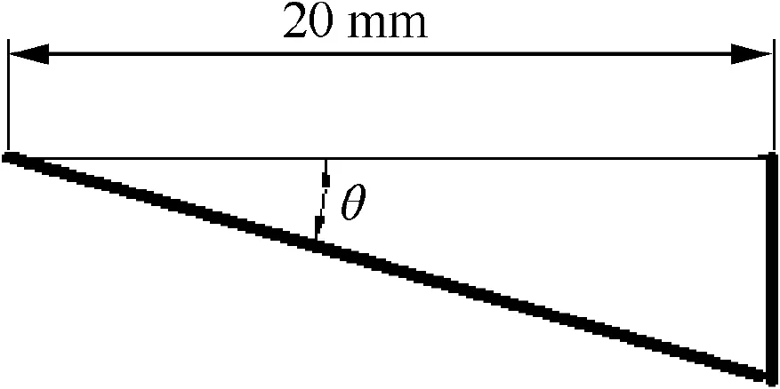
Fig. 3 Shock wave generator.
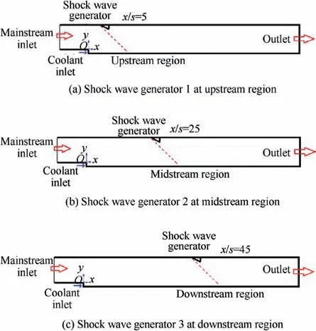
Fig.4 Supersonic film cooling models considering three impinging regions.
2.2. Model validation
For the numerical simulation of supersonic film cooling, the choice of turbulence model is of great importance, which has a great effect on the numerical results. Thus, firstly we have set up a validation experiment, using the results of the validation experiment to help making a suitable choice of turbulence model.
As shown in Fig.5,the air was compressed by the air compressor into the air container, then the flow was divided into two loops after drying by the water filter. For one loop, the air was heated by the electric heater to high temperature required for the experiment, and then flowed through a Laval nozzle to become supersonic at the test section.The other loop was the coolant loop which was injected through a Laval nozzle to form a cooling film layer to protect the wall.The test section was 140 mm long, 30 mm high and 20 mm wide. The coolant nozzle exit slot was s=4 mm high and the thickness of separating lip was t=0.5 mm. The shock wave generator was 20 mm long with the height depended on the angle. The shock wave generator was located at x/s=5,the experimental section was shown in Fig. 6. Different intensity shock waves were formed by changing the shock wave generator angle with larger angles giving stronger shock waves. The thermocouple could measure the total temperature of the mainstream and the cooling stream,the uncertainty was±0.2 K.The protected wall temperature was measured by infrared camera, the uncertainty in the present study was±0.5 K.The cooling wall was made of low thermal conductivity Bakelite,the test section was protected by insulation,so that the wall could be assumed to be nearly adiabatic.In the experiment,the mainstream temperature was 393 K and the cooling stream temperature was 328 K. The total pressure of the mainstream was 485,000 Pa and the static pressure was 9800 Pa,so that the Mach number of the mainstream was 3.2. The static pressure of the cooling stream is the same as that of the mainstream and the coolant Mach number was 1.2.

Fig. 6 Experimental section.

Fig. 5 Experimental system.
Three Reynolds Averaged Navier-Stokes (RANS) models,the realizable k-ε model, Spalart-Allmaras (SA) model, and Shear Stress Transport(SST)k-ω model were used to perform numerical simulation. Fig. 7 showed the comparison of the numerical results and the experimental data, which illustrated that the SST k-ω model predictions gave better accordance to the experimental data than the other models.
The study by Konopka et al.36showed that LES model gave a more correct prediction of the length potential-core region and a better capture of the flow phenomena. As shown in Fig. 8, the difference in the prediction of velocity distributions between the SST k-ω model and the Konopka et al.36was small. In addition, the present study gave a qualitative comparison about the three impinging regions, so the SST k-ω model was applied.
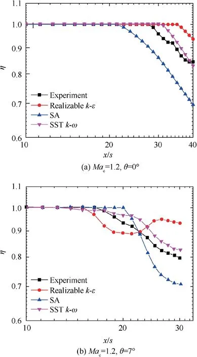
Fig. 7 Turbulence model validation.

Fig. 8 Comparison of numerical results with the data of Konopka et al.
2.3. Governing equations
The general form of the governing equation is as followed and Tables 1 and 2 show the definition and explanation of the defined variables in each equation.

The CFD software Ansys-Fluent 16.0 was used for the present numerical calculation. The numerical simulation used the implicit formulation of the density based solver. The Advection Upstream Splitting Method (AUSM) was used to model the convective flux terms. Central differences were applied for the diffusion and pressure terms in the momentum equation and the divergence terms in the mass continuity equation.The second-order upwind scheme was used to evaluate the convective terms in the momentum, energy, mass transport,turbulent kinetic energy, and specific dissipation equations.The convergence criteria are that the residuals of all variables are less than 10-3.
2.4. Calculation conditions
The calculation conditions remained the same as experimental conditions. The total temperature of the mainstream was 393 K, and the cooling stream was 328 K. The total pressure of the mainstream was 485 kPa with the static pressure of 9800 Pa. The static pressure of the cooling stream was the same as that of the mainstream to avoid the generation of shock wave when the streams met at the coolant inlet. The total pressure of the cooling stream was 23.79 kPa for the Mac=1.2 and 36.0 kPa for the Mac=1.5.
The mainstream inlet Mach number was 3.2 for all the cases, and the cooling stream Mach number was 1.2 or 1.5.The outlet was set as pressure outlet condition and the other walls were set as adiabatic with the no-slip conditions.
The detailed calculation conditions are listed in Table 3.
2.5. Important parameters
The adiabatic supersonic film cooling effectiveness is defined as:


Table 1 Variables for each equation.
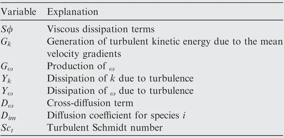
Table 2 Explanation for variables defined in each equation.
where Tawrepresents the temperature of the local adiabatic wall and Tr∞and Trcare the recovery temperature of mainstream and cooling stream defined as:

where γ represents the adiabatic coefficient, r is the recovery factor, which equals to Pr1/3for the cooling stream and the mainstream.
The blowing ratio is defined as:

where ρcand ucdenote the density, velocity of the cooling stream, ρ∞and u∞denote the density, velocity of the mainstream respectively. ρcucand ρ∞u∞represent the momentum of the cooling stream and the mainstream.
2.6. Mesh
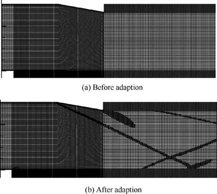
Fig. 9 Calculation mesh before and after adaption.
The grid independence verification indicated that 150,000 elements were suitable for the numerical calculation. The mesh adaption function in Ansys-Fluent was used to adjust the mesh, which could give a better capture of the shock wave.The number of elements after mesh adaption was 160,000 for each case. By comparing the numerical results with the experimental data,it was found that when the y+near the protected wall was refined to less than 5 for most of the cells in the shock wave impinging region and about 30 outside the impinging region, the simulation results were closer to the experimental data.SST k-ω turbulence model was an adaptive model,which could switch automatically from the viscous sublayer formulation to the wall function,depending on the grid.41The meshes before and after the adaption were shown in Fig. 9.
3. Results and discussion
3.1. Influence of the shock wave generator position
The influence of the shock wave generator position on the film cooling effectiveness was shown in Fig. 10, where SG1, SG2 and SG3 referred to the three shock wave generator positions.For the 4° shock wave generator, there were few differencesoutside the shock wave impinging region. However, when the shock wave is stronger, the film cooling effectiveness with the upstream shock wave generator was lower than that with the midstream position or the downstream position. Thus, the upstream shock wave generator had a stronger damaging effect compared to the other two positions.

Table 3 Calculation conditions.
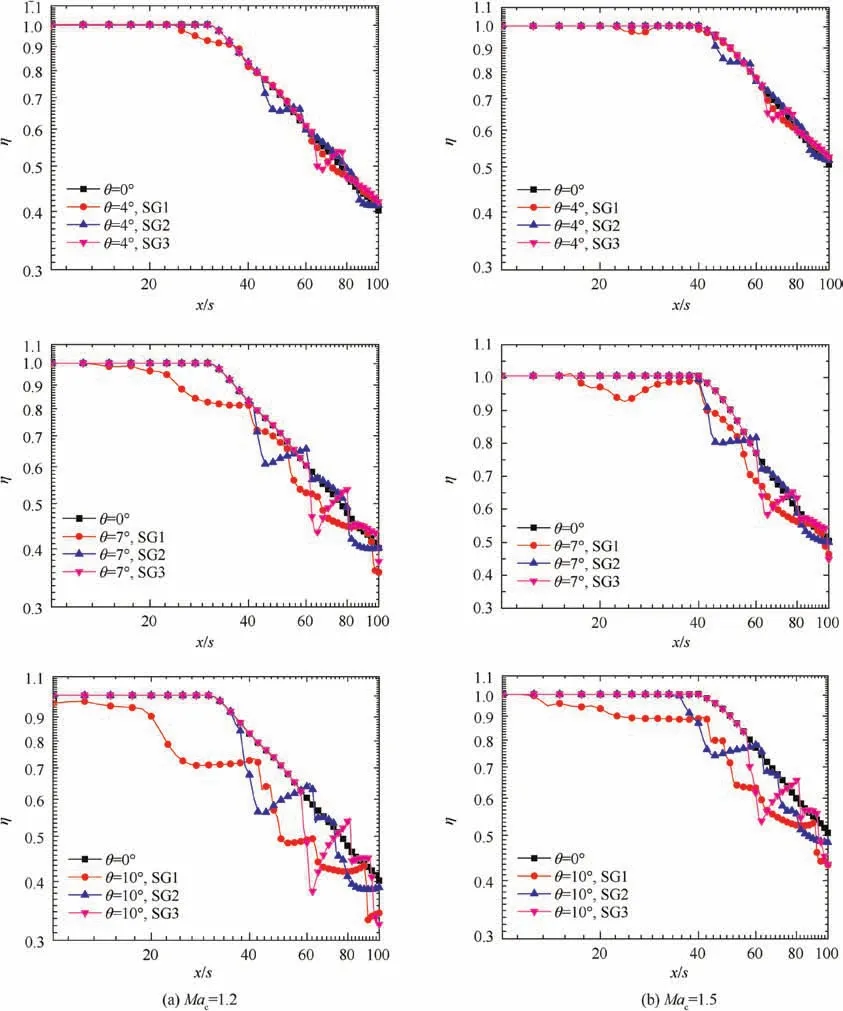
Fig. 10 Film cooling effectiveness distributions for various shock wave generator positions.
The cases of shock wave impinging in the upstream region were used to analyze shock/cooling film interaction. There were two important mechanisms for the interaction between the shock wave and the cooling film. Firstly, the shock wave would form a high-pressure region in the impinging region with the local pressure rapidly increased, as shown in Fig. 11, which led to a rapid decrease in local Mach number shown in Fig.12.For supersonic flow,the adiabatic wall temperature can be given by:

where Toerepresents the fluid total temperature, Ma is the local Mach number. Therefore, from the qualitative analysis,as the local Mach number decreased, the adiabatic wall temperature increased and the film cooling effectiveness decreased.
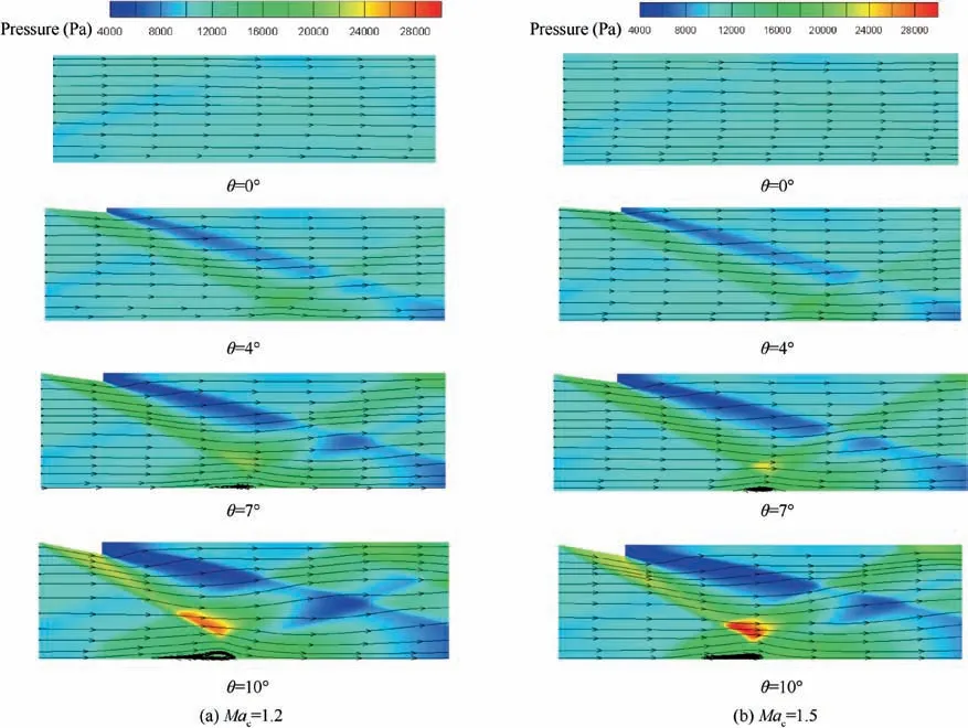
Fig. 11 Pressure distributions and streamlines with the upstream shock wave generator.
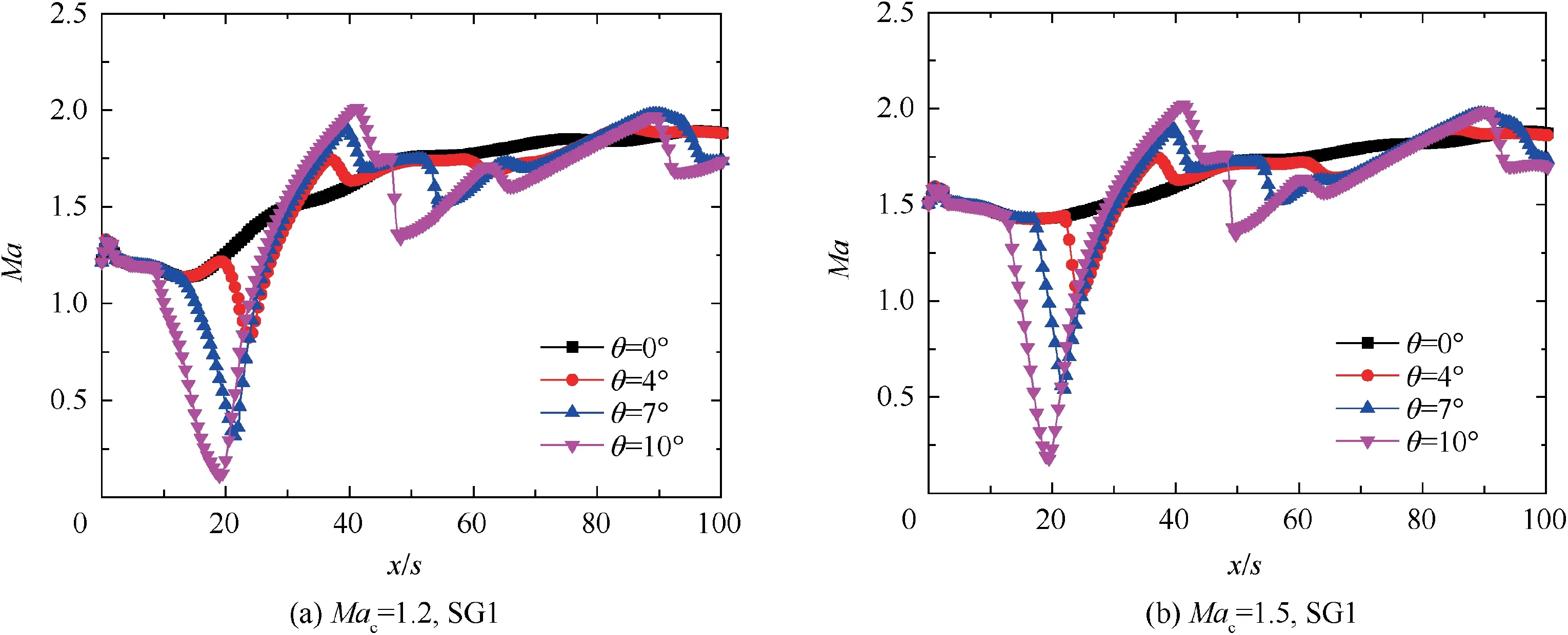
Fig.12 Mach number: 2 mm above the adiabatic wall with the upstream shock wave generator.
Secondly, the shock wave would lead to more intense mixing between the mainstream and the cooling stream.As shown in Fig. 11, the 10° shock wave also created a vortex in the impinging region which lifted the cooling stream and increased the mixing degree. The sharp increase of the turbulent kinetic energy shown in Fig. 13 also indicated that the shock wave enhanced the mixing of the mainstream with the cooling stream, which caused the high-temperature mainstream to enter the cooling film layer and thereby reduced the film cooling effectiveness.
The cases with 10°shock wave incidence were used to compare the three shock wave generator positions. The pressure distributions with streamlines for various positions of the 10°shock wave generator were shown in Fig.14 and the turbulent kinetic energy in the boundary layer 2 mm above the wall was shown in Fig.15.The results showed that when the shock wave impinged in the upstream region, there formed a larger pressure rising region and a larger-size vortex near the protected wall,so the turbulent kinetic energy was larger in the boundary layer. The pressure distribution on the protected wall was shown in Fig. 16. The results manifested that with upstream impingement, although the pressure was lower, the pressure rising region was wider, according to previous study,38larger pressure rising region caused larger damaging effect. The Mach number distribution 2 mm above the wall was shown in Fig. 17. The results showed that the Mach number in the case of upstream impingement was lower than the others,which would weaken the film cooling effectiveness. Thus, the shock wave in the upstream region was more destructive to the film cooling effectiveness.
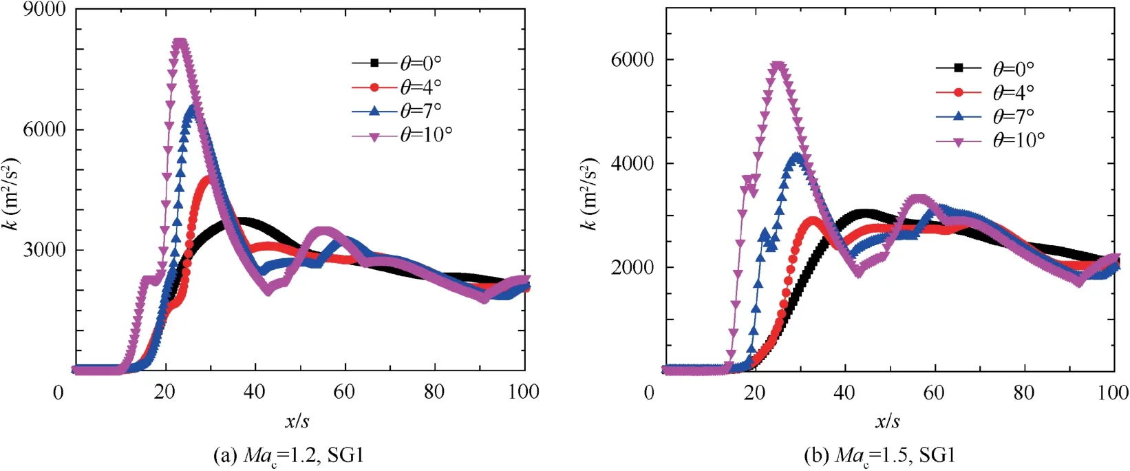
Fig.13 Turbulent kinetic energy: 2 mm above the adiabatic wall with the upstream shock wave generator.
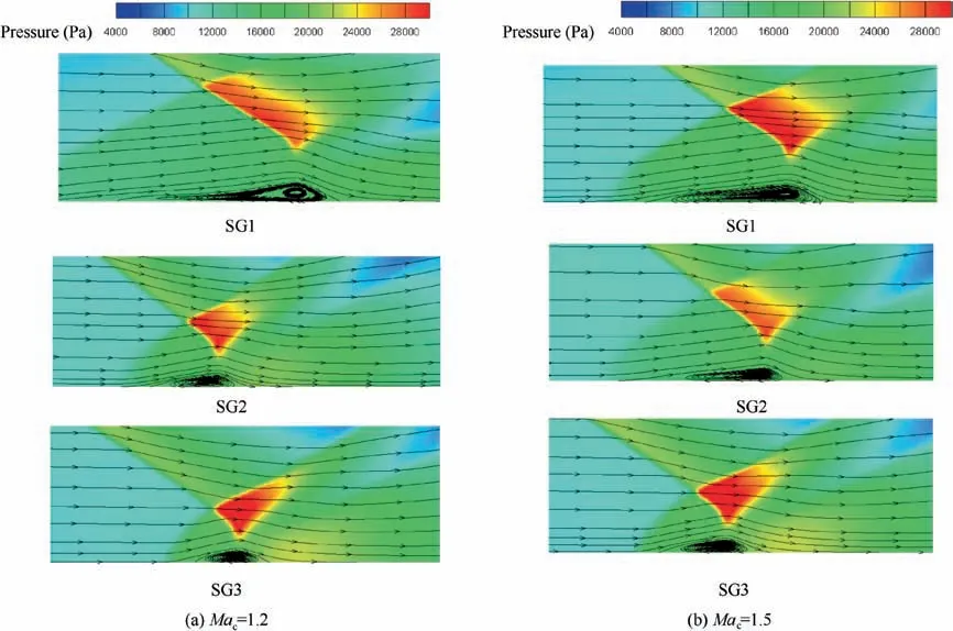
Fig. 14 Pressure distribution and flow streamlines for various positions of the 10° shock wave generator.
The mass fraction of the coolant gas in the boundary layer near the protected wall was shown in Figs. 18 and 19. The results showed that the mass fraction of the coolant gas decreased due to the shock wave impingement, especially for the case of the shock wave generator in the upstream region,the coolant gas mass fraction in the downstream region (x/s >20) was lower than the cases of the shock wave generator in the midstream and downstream region, which meant the shock wave impinging in the upstream region had the largest influence.
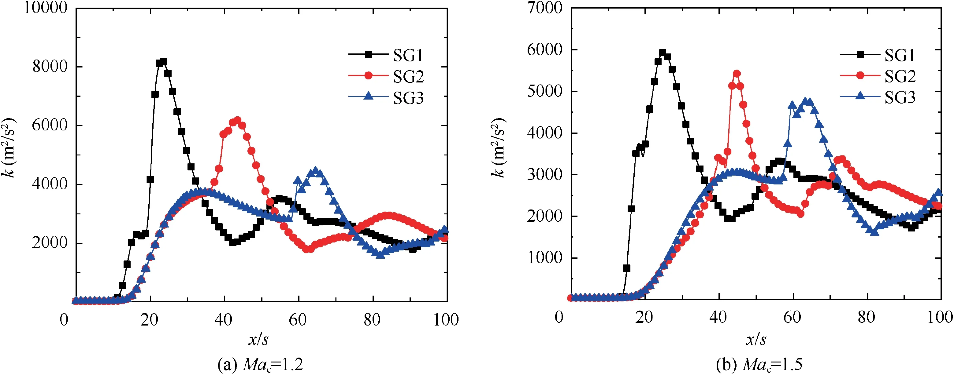
Fig. 15 Turbulent kinetic energy in the boundary layer 2 mm above the wall.

Fig. 16 Pressure distribution on the protected wall.

Fig. 17 Mach number distribution in the boundary layer 2 mm above the wall.
The Mach numbers along the y direction in the boundary layer in the shock wave impinging region were shown in Fig. 20. The coolant injection Mach number was lower than the mainstream Mach number, so the Mach number in the boundary layer increased with the mixing between the mainstream and the cooling stream, which increased the resistance of the cooling film to the shock wave impingement. In the upstream region, the velocity in the boundary layer was relatively low, so the fluid has a low boundary-layer momentum with less ability to resist the impingement of the incident shock wave than in the faster downstream flow,42giving a lower cooling effectiveness.In the downstream region,the velocity in the boundary layer was higher and the shock wave had less influence on the film cooling.
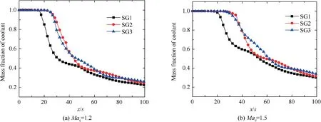
Fig. 18 Mass fraction of coolant flow in the boundary layer near the wall.
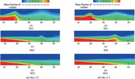
Fig. 19 Mass fraction distribution of coolant for various positions of the 10° shock wave generator.
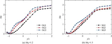
Fig. 20 Mach number in the boundary layer of shock wave impinging region for 10° shock wave generator.
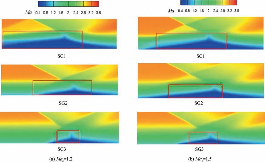
Fig. 21 Mach number distribution for various positions of 10° shock wave generator.
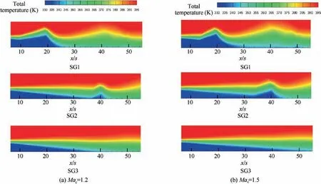
Fig. 22 Total temperature distribution for various positions of 10° shock wave generator.
The distribution of the Mach number in the shock wave impinging region and the total temperature were shown in Figs. 21 and 22. The shock wave impinging in the upstream region not only created a larger vortex shown in Fig. 14, but also formed a larger low Mach number region, so the mixing between the mainstream and the cooling stream was enhanced greatly. Moreover, in the case of shock wave impingement in the upstream region, the mainstream and the cooling stream mixed earlier. The earlier and more intense mixing resulted in a higher temperature of the protected wall in the midstream and downstream region. Therefore, the shock wave impinging in the upstream region deteriorated supersonic film cooling to a larger extent.
3.2.Influence of shock wave intensity and coolant Mach number
The numerical results in Fig. 23 showed that for a given coolant Mach number and shock wave generator position, the stronger shock wave gave rise to the lower film cooling effectiveness.For the shock wave impinging in the upstream region,the difference in film cooling effectiveness for different shock wave intensities was larger.
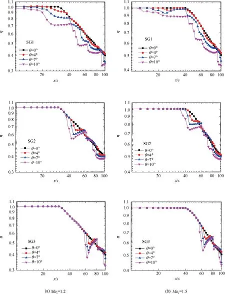
Fig. 23 Predicted film cooling effectiveness distributions.
The case of 10° shock wave generator was again used to analyze the influence of the coolant Mach number with the results shown in Fig. 24. The results illustrated that the larger coolant inlet Mach number was more beneficial to film cooling. As for the reason, the blowing ratio M was an important factor influencing the mixing. The larger blowing ratio M meant that the difference in momentum between the mainstream and the coolant flow was smaller, which could weaken the mixing. The blowing ratio for Mac=1.2 was M=0.267,while for Mac=1.5 was M=0.353. Thus, increasing the coolant inlet Mach number increased the blowing ratio.The turbulent kinetic energy distributions 2 mm above the wall shown in Fig. 25 showed that for the higher coolant Mach number, the turbulent kinetic energy was lower, which meant less mixing of the mainstream with the cooling stream,so the higher coolant Mach number improved the film cooling.
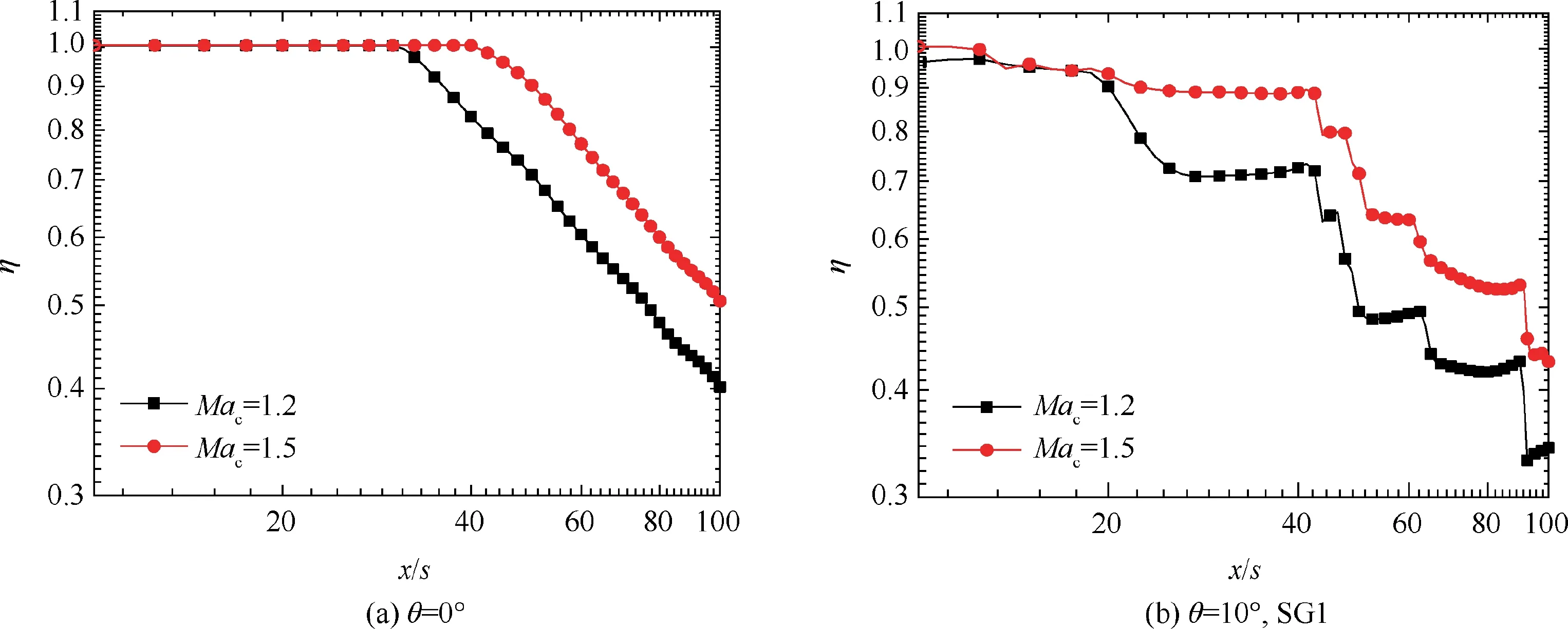
Fig. 24 Film cooling effectiveness distributions for two coolant Mach numbers.
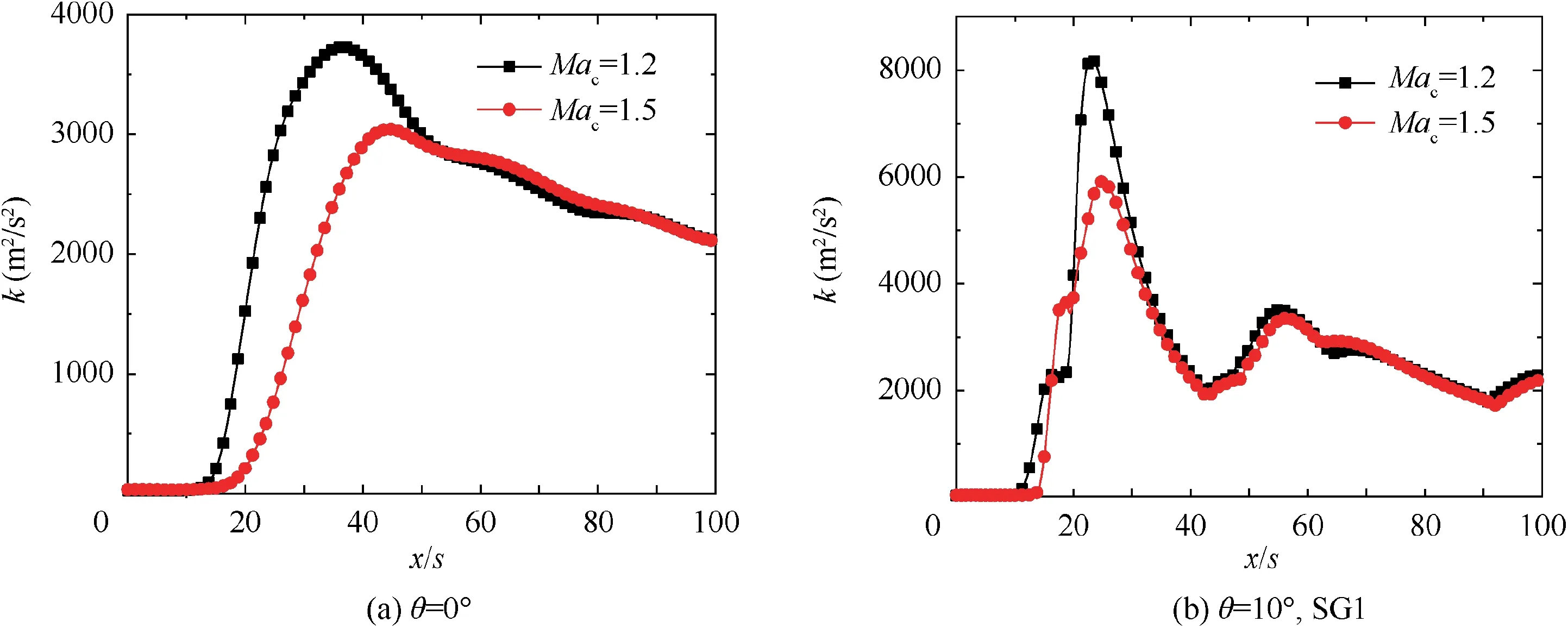
Fig. 25 Turbulent kinetic energy 2 mm above adiabatic wall.
4. Conclusions
The present study numerically compared the results of three impinging regions and analyzed the influence of shock wave impinging region on supersonic film cooling for various shock wave intensities and coolant Mach numbers. The results indicated that:
(1) When the shock wave generator was further upstream,the pressure changing region in the cooling layer was larger which created a larger vortex at the point where the shock wave impinged upon the wall,resulting in a larger decrease of the local Mach number and more intense mixing between the mainstream and cooling stream, so the film cooling effectiveness was lower.
Later in life, I wondered how she could know so much about me that I did not know about myself. She knew even though my marks were average in school, that I was just bored but smart enough. She believed in me even when I made mistakes that caused others to shudder10. She wanted me to be more than she had been, when I thought she was everything I wanted to be.
(2) The velocity in the upstream part of the cooling layer was relatively low,so the cooling layer had less ability to resist the negative effect of the shock wave impingement,which decreased the cooling effectiveness significantly when the shock wave generator was in the upstream position.
(3) The velocity of cooling layer in the midstream and downstream region was higher, which was beneficial to inhibit the shock wave impingement. When the impinging region was closer to the downstream region, the influence of shock wave was smaller.
(4) The impinging shock wave reduced the supersonic film cooling effectiveness with a larger shock wave generator angle leading to a lower film cooling effectiveness. As the coolant Mach number increased, the blowing ratio increased and the difference in momentum between the mainstream and the cooling stream decreased, which reduced the mixing and gave a higher film cooling effectiveness.
Declaration of Competing Interest
The authors declare that they have no known competing financial interests or personal relationships that could have appeared to influence the work reported in this paper.
This project was supported by the the National Science and Technology Major Project of China(No. 2017-III-0003-0027),the Science Fund for Creative Research Groups of the NSFC(No.51621062) and Tsinghua University-Zhang Jiagang Joint Institute for Hydrogen Energy and Lithium-Ion Battery Technology.
 CHINESE JOURNAL OF AERONAUTICS2021年5期
- CHINESE JOURNAL OF AERONAUTICS的其它文章
- Ferrofluid moving thin films for active flow control
- Preliminary study on heat flux measurement data of TT-0 flight test
- An analysis and enhanced proposal of atmospheric boundary layer wind modelling techniques for automation of air traffic management
- Jet sweeping angle control by fluidic oscillators with master-slave designs
- Hot deformation behavior and microstructure evolution of the laser solid formed TC4 titanium alloy
- Electrochemical trepanning with an auxiliary electrode
