Reflection of a moving shock wave over an oblique shock wave
Miaomiao WANG, Ziniu WU
Department of Engineering Mechanics, Tsinghua University, Beijing 100084, China
Keywords: Shock reflection; Triple point; Unsteady shock wave* Corresponding author.
Abstract The reflection of a moving shock wave over a wedge immersed in a still gas and the reflection of a wedge induced steady shock wave over symmetrical and asymmetrical reflecting surfaces have received intensive considerations since more than 70 years ago. Here we consider a different shock reflection problem—reflection of a moving shock wave over an initially steady oblique shock wave induced by a wedge immersed in supersonic flow.For the flow condition we considered,five moving triple points,with each connecting an incident shock wave,a reflected shock wave and a Mach stem,are identified.By using the reference frame co-moving with each triple point,the type of each shock wave of this triple point is clarified.The present study is significant in that it treats a new shock reflection problem leading to a new shock reflection configuration and showing potential applications in supersonic flow with unsteady shock interaction.
1. Problem statement
The problem we consider is schematically displayed in Fig. 1.A supersonic flow with Mach number Ma0impinges a wedge with wedge angle θwso that we initially have a steady oblique shock wave.


Now an incident shock wave moving rightward is generated at the entry.We are interested in how this incident shock wave reflects over the oblique shock wave.This defines a new shock reflection problem, since steady shock reflection, pseudosteady shock reflection and unsteady shock reflection studied previously did not appear to cover this case, see the monograph by Ben-Dor.1
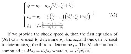
This incident shock wave belongs to the first family of moving shocks.Let this incident shock wave move at speed φ,then the flow status at the left hand side of Eq.(A2)are determined by the moving shock relations as given in Appendix A.1.
In this paper, we only display results for Ma0= 6, ρ0=0.427 kg/m3, p0=30000 Pa, θw=22.5oand φ=1750 m/s.Using other flow conditions may lead to similar or different flow patterns. Using the oblique shock wave relation we get β= 31.21o,Ma1=3.097,p1=3.333×10⁵Pa,ρ1=1.687 kg/m3.Using the moving shock wave relation (A2) provided in Appendix A.1, we get u2=2389.0 m/s, ρ2=0.0888 kg/m3,p2=1289.2 Pa and Ma2=16.8.
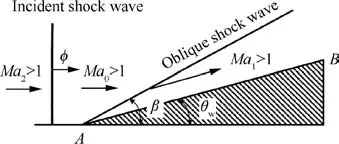
Fig. 1 An incident shock wave going to reflect over a steady oblique shock wave.
A common feature of classical shock reflection is that it involves a single triple point or multiple triple points. A triple point connects three shock waves and a slipline, see Appendix A.1 for more details and for the von Neumann three shock theory to determine the flow parameters in the vicinity of the triple point.
2. Statement of results
We use computational fluid dynamics to obtain the flow and then use shock theory to identify the reflection configuration.The numerical method used is stated in Appendix A.2. The Mach contours at two typical instants τ are displayed in Fig. 2. Here τ is the non-dimensional time defined by τ = V∞t/AB where t is measured from the instant at which the incident shock wave touches A and AB is the length of wedge.It can be seen that the flow structures are similar at different instants. This means that the shock reflection structure is self-similar.
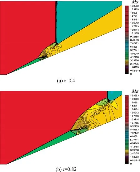
Fig. 2 Mach contours.
The flow structure appears to be more complex than what we know about steady shock reflection2and pseudo steady shock reflection.3As usual,the flow pattern can be understood by identifying the interaction points including triple points and slipline-shock interaction points.Since triple points are moving in the present problem, it is interesting to identify that, for each triple point, which shock wave is the incident one, the reflected one and the Mach stem.This information is very hard to identify from the ground frame, since each triple point is moving and at its own speed and direction, as will be shown later.
In Appendix A.3, we provide a method to resolve such a difficulty. This method consists to update the flow velocity in the frame co-moving with each triple point and redesign the Mach contours and streamlines using the updated velocity.The resulting flow pattern is then compared with a steady triple point to identify the nature of shock waves.
With this method of identifying the triple point structure,we are able to identify the local incident shock wave, local reflected shock wave and local Mach stem for each triple point,and the result is displayed in Fig. 3. We observe five triple points, labeled respectively a, b, c, d and e, plus two sliplineshock intersection points, labelled f and g. Consider for instance the triple point c, shock with label icis the incident shock wave for triple point c,shock with label rcis the reflected shock wave for triple point c and mcis the Mach stem for triple point c.The slipline with label scis the slipline from triple point c.
Now consider the relations between triple points and shock waves. First we note that the shock wave (aP) is a newly generated oblique shock wave with upstream Mach number Ma2= 16.8. Since Ma2>Ma0, its shock angle β2= 27.96ois smaller than that of the original oblique shock wave(β0= 31.21o). The five triple points connect 10 segments of shock waves and 5 sliplines, as displayed in Table 1, where we also give the velocity VT=(uT,vT) of each triple point.
3. Significance of results
The problem considered may have interesting practical applications. For instance, once a supersonic or hypersonic vehicle encounters the shock wave of an upstream vehicle moving more slowly, the shock wave of the latter may reflect over the shock wave of the former.4The complex unsteady shock reflection configuration expanding its extension in time will alters the lift and drag of the vehicle. The evolution of lift and wave drag of such a problem is interesting and will be studied in the future. For supersonic intake the shock reflection may be subjected to disturbance of an upstream disturbance, which defines a problem similar to the present one if the upstream disturbance is a shock wave. Kudryavtsev et al.5considered such a case with focus on transition of the initial regular reflection of the steady shock wave, without clarifying how the moving shock wave reflects over the initially steady shock wave attached to the wedge.
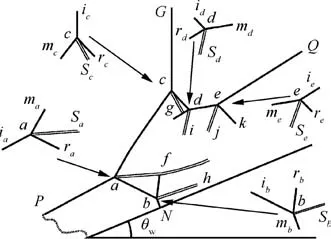
Fig. 3 Shock reflection pattern with five triple points.

Table 1 Triple point information.
The present problem also defines a fully new shock wave reflection pattern. Previously considered symmetrical and asymmetrical shock reflection involves only two triple points,6,7and pseudo-steady shock reflection involves only one to two triple points.2However, the present problem has five triple points, much more complex than problems considered before.
Some of the physical reasons for generation of triple points can be easily explained. Consider for instance triple point a of Fig.3,its reflected shock(ab)reflects again on the wedge,leading to a Mach reflection at point N,which further leads to triple point b. Consider further triple points d and e. It is in fact due to asymmetric Mach reflection between the reflected shock wave (cd)of triple point c and the shock wave (eQ). The most difficult problem is how triple e is formed.
Finally, the present problem leads to a new fundamental question that deserves to be studied. It is well known that for pseudo steady and purely unsteady shock reflection, there is some difficulty to find the physical mechanism by which the velocity of moving triple points can be determined,8,9even though this subject has been studied since more than 40 years ago.10Even for the well studied pseudo steady reflection of a moving shock over a wedge immersed in a still gas, the triple point velocity in case of only one triple point has been determined using assumptions that the Mach stem is perpendicular to the wedge.11The mechanism by which the path or velocity of the five triple points shown in Fig.3 is certainly much more complex than that studied before and may constitute an interesting problem for further study.
Declaration of Competing Interest
The authors declare that they have no known competing financial interests or personal relationships that could have appeared to influence the work reported in this paper.
Acknowledgements
The authors are grateful to all referees for their valuable comments that helped to improve the manuscript. This work was supported partly by the National Key Project (No.GJXM92579)and the National Science and Technology Major Project (No. 2017-II-003-0015).
Appendix A. Method of analysis
A.1. Shock relations and von Neumann three shock theory
The functions fθ(Ma0,β), fp(Ma0,β), fM(Ma0,β) and fρ(Ma0,β) used in steady oblique shock wave relations as required in Section 1 are

For a normal moving shock wave of the first family,applied to the incident shock wave of Fig. 1, the shock relations are given by
Now consider a typical triple point. Fig. A1 displays the typical structure of triple point,the three shock waves are incident shock wave (i), reflected shock wave (r) and Mach stem(m). There is a slipline (s) separating the flow behind the reflected shock wave and Mach stem.

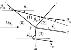
Fig. A1 A triple point.
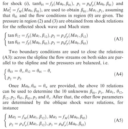
A.2. Numerical method
We use computational fluid dynamics with adaptive grid refinement to solve the Euler equations in gas dynamics. As displayed in Fig.A2(a),supersonic inflow boundary condition is imposed at the entry, first with a Mach number 6 and then with a Mach number 16.8 (more flow parameters are given in Section 1). Supersonic outflow condition is prescribed on the right boundary.The lower boundary is a reflecting surface and the upper boundary is a symmetry.
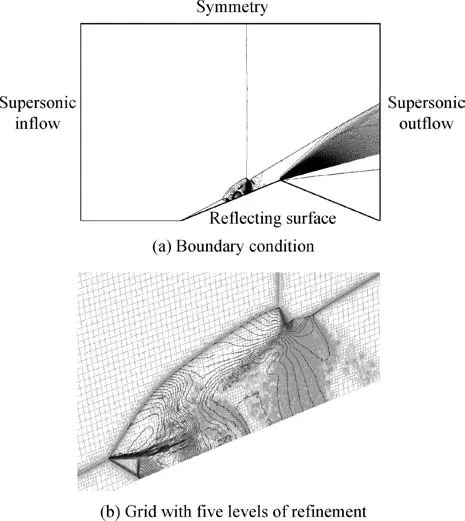
Fig. A2 Boundary condition and grid with five levels of refinement.
Fig.A2(b)displays how the grid is refined locally.This grid refinement allows us to capture correctly the local flow structure.
The AUSM scheme is used to solve the unsteady Euler questions. The grid refinement and the time step are refined until the necessary details of the flow structure are captured.
A.3. Method to identify nature of three shock waves connecting to a moving triple point
To identify the nature of shock waves attached to a moving triple point,we propose to attach the reference frame to the corresponding triple point and redesign the streamlines. Once the flow is thus obtained, the frame is further rotated in such way that the local inflow streamlines are horizontal. We then compare the flow structure with the typical triple point configuration shown in Fig. A1 to determine which shock is incident,reflected or being the Mach stem.
Consider for instance triple point c of Fig. 3. Fig. A3 displays the Mach contours and streamlines, with the flow velocity being measured in the frame co-moving with the triple point (see Table 1 for the velocity of each triple point). With such a process, we are able to identify that shock (cG) is the local incident shock wave, shock (cd) is the local reflected shock wave and shock (ca) is the local Mach stem.
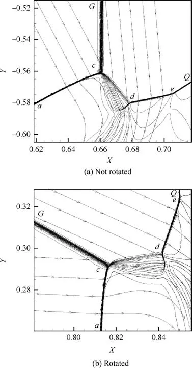
Fig. A3 Mach contours in the frame co-moving with point c.
 CHINESE JOURNAL OF AERONAUTICS2021年5期
- CHINESE JOURNAL OF AERONAUTICS的其它文章
- Ferrofluid moving thin films for active flow control
- Preliminary study on heat flux measurement data of TT-0 flight test
- An analysis and enhanced proposal of atmospheric boundary layer wind modelling techniques for automation of air traffic management
- Jet sweeping angle control by fluidic oscillators with master-slave designs
- Hot deformation behavior and microstructure evolution of the laser solid formed TC4 titanium alloy
- Electrochemical trepanning with an auxiliary electrode
