Multi-scale design and optimization for solid-lattice hybrid structures and their application to aerospace vehicle components
Chung WANG, Jihong ZHU,b,*, Mnqio WU, Jie HOU, Hn ZHOU,Lu MENG, Chenyng LI, Weihong ZHANG
a State IJR Center of Aerospace Design and Additive Manufacturing, Northwestern Polytechnical University, Xi’an 710072, China
b MIIT Lab of Metal Additive Manufacturing and Innovative Design, Northwestern Polytechnical University, Xi’an 710072, China
c Science and Technology on Space Physics Laboratory, China Academy of Launch Vehicle Technology, Beijing 100076, China
KEYWORDS Aerospace vehicle components;Lattice-based optimization;Multi-scale;Solid-lattice hybrid structure;Topology optimization
Abstract By integrating topology optimization and lattice-based optimization,a novel multi-scale design method is proposed to create solid-lattice hybrid structures and thus to improve the mechanical performance as well as reduce the structural weight. To achieve this purpose, a two-step procedure is developed to design and optimize the innovative structures. Initially, the classical topology optimization is utilized to find the optimal material layout and primary load carrying paths.Afterwards,the solid-lattice hybrid structures are reconstructed using the finite element mesh based modeling method. And lattice-based optimization is performed to obtain the optimal crosssection area of the lattice structures. Finally, two typical aerospace structures are optimized to demonstrate the effectiveness of the proposed optimization framework. The numerical results are quite encouraging since the solid-lattice hybrid structures obtained by the presented approach show remarkably improved performance when compared with traditional designs.
1. Introduction
In the fields of aircraft and aerospace vehicle design, lightweight and high-efficiency structures are the eternal pursuit of engineers. Traditionally, size and shape optimizations are the main techniques and have been widely employed.1-3With the emergence and rapid development of topology optimization, this revolutionary technology has already caught numerous scholars’ attention and gained significant progress in both fundamental research and practical application over the last several decades.4-8Generally speaking, topology optimization intends to find an optimal material layout in a given design domain with prescribed boundary conditions and constraints.Recently,widely used in many engineering fields,9-11especially in aircraft and aerospace field,12-15topology optimization has become a highly effective tool to create innovative designs characterized by improved performance and reduced weights.One of the most representative design cases can be found in the study of Krog et al.,13where the wing structure of Airbus A380 was optimized using topology optimization. The final leading-edge ribs design of Airbus A380 was obtained with a significant weight loss while meeting all the design requirements. Additionally, Aage et al.16reported a computational morphogenesis tool to design the internal structure of a fullscale airplane wing using topology optimization.Furthermore,the literature survey17has summarized and highlighted the recent advances and applications of topology optimization in designing aircraft and aerospace structures.
Apart from macroscopic structural design, recent significant advance on multi-scale design methods enables researchers and engineers to consider microscopic structural topologies when pursuing light-weight and high-performance structures.18Generally, due to their flexible designability, multi-scale structures are used to enhance the structural performance,e.g.,stiffness,19energy absorbability,20,21shock resistance22and heat insulation.23-25Especially from the perspective of lightweight design, the principle function of lattice structures is able to reduce weight while keeping the load bearing capability. Consequently, the lattice-based multi-scale structures have been extensively investigated in theory and widely used in engineering applications. Wu et al.26presented a generalized approach for the design of hierarchical lattice structures without assuming scale separation to address the length ratio issue. Watts et al.27provided accurate surrogate models of the homogenized linear elastic response of three-dimensional open truss micro-architectures. Based on these surrogate models, they solved a multi-scale compliance design problem with spatially varying lattice structures. Besides, Wang et al.28developed a novel design method to obtain hierarchical structures with non-uniform lattice microstructures based on Parameterized Interpolation for Lattice Material(PILM)model.Tang et al.29proposed an innovative design method for the creation of periodic lattice structures by defining functional volume and functional surface. In this work, an optimized aircraft engine bracket is fabricated by additive manufacturing, which offers an important basis for the wide application of additive manufacturing in the industry.Furthermore,Zhang et al.30designed a lightweight satellite structure based on lattice sandwich panels. The whole satellite structure was manufactured by direct metal laser melting using aluminum alloy AlSi10Mg.The ratio of structure’s weight to satellite weight is much superior to the traditional satellite structures.
Nevertheless, to our surprise, the stiffness of the lattice structures mentioned above is generally worse than that of solid structures with the same weight. To deal with the issue,Dong et al.31has made efforts to design the solid-lattice hybrid structures for better mechanical performance.Inspired by this,Dong et al.32proposed a novel design method to optimize solid-lattice hybrid structures by the Bidirectional Evolutionary Structural Optimization (BESO) method. Additionally,He et al.33performed topology and lattice optimization to design a hip prosthesis for reducing stress shielding and meeting fatigue requirements. The optimized solid-lattice design reduced stress shielding by 50+%when compared with a conventional generic implant. Boccini et al.11explored a novel approach to optimize a turbine disk by integrating topology optimization and innovative lattice structure. The obtained results clearly demonstrate the superior resonance performance of the solid-lattice design over the traditional solid design. Unexpectedly, despite being a heated topic in recent years, the extraordinary potential of the solid-lattice hybrid structures has not yet been extensively developed to study aerospace vehicle components. Consequently, a systematic and high-efficiency multi-scale design method is still in great demand to enhance the design capability of aerospace vehicle components for better performance and lighter weight.
Based on the above considerations, the multi-scale design method for solid-lattice hybrid structures and their applications to aerospace vehicle components are herein explored.The general goal of the presented method is to generate manufacturable solid-lattice hybrid structures with better performance while meeting all design requirements. To achieve this purpose, a two-step procedure is carried out to design and optimize solid-lattice hybrid structures by the combination of topology optimization and lattice-based optimization. The remainder of this paper is organized as follows.Section 2 provides a detailed description of the modeling and design method for solid-lattice hybrid structures. Thereafter, the sensitivity analysis is presented in Section 3. Two numerical examples for aerospace vehicle components design are implemented in Section 4, which is followed by the concluding remarks in Section 5.
2.Modeling and design method for solid-lattice hybrid structures
In this work,the solid-lattice hybrid structures are obtained by integrating topology optimization and lattice-based optimization. This approach allows implementing a solution using the two-step procedure (Fig. 1). Step 1: Perform a conventional topology optimization based on solid isotropic material with penalty (SIMP) model and then find the optimal material layout. Afterwards, identify the primary load carrying paths according to the high pseudo-density values and reconstruct the solid part of a structure. Step 2: Build the relationships between the element densities and lattice unit cells and then create the lattice part according to the low pseudo-density values. Later on, carry out lattice-based optimization to obtain the optimal cross-section area of the lattice structures under prescribed boundary conditions and constraints. illustrates a systematic design procedure for a solid-lattice hybrid rudder structure. It should be mentioned that the selected case contributes to understanding the main steps to carry out the procedure. The approach presented in this work is generic, and therefore it can be implemented for any other structure.
2.1. Topology optimization based on SIMP model
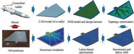
Fig. 1 Systematic procedure of proposed approach.
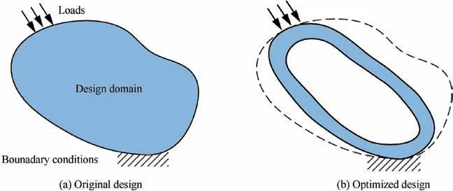
Fig. 2 Illustration of topology optimization design.
As already mentioned in the introduction, topology optimization is a powerful tool to obtain the optimal material layout under the prescribed loading and boundary conditions at the concept design stage, as shown in Fig. 2. As the most popular method of topology optimization, the solid isotropic material with penalization (SIMP) method is applied here due to its simplicity and high efficiency in numerical implementation.The density-based method usually treats the element density,so-called pseudo-density, as the design variable in topology optimization. The value of pseudo-density ranges from 0 to 1,with 0 describing a void element and 1 describing a solid element. Although the pseudo-density can take values between 0 and 1,the intermediate density values have no proper physical interpretations.To ensure good convergence to 0/1 designs,the SIMP interpolation model works by penalizing exponentially isotropic material in terms of pseudo-density variables with a power law scheme
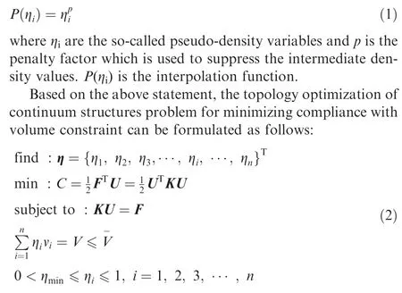
where ηidenotes the pseudo-density of the i-th element and n is the number of elements in the design domain.As the objective function, C represents the overall compliance of the structure.viis the volume of the i-th element and V is the total volume of the design domain with the upper bound ∇. In order to avoid the numerical singularity, ηmin is set as a small positive value as the lower bound of the pseudo-density variable. Based on the assumption of linear elasticity, the compliance minimization problem meets the static equilibrium equation KU=F.U and F denote the nodal displacement vector and the external load vector, respectively. The global stiffness matrix K assembled by the element stiffness matrix kican be written as

where B is the strain matrix, Diis the elastic matrix and Ωidenotes the domain of the i-th element. Using the SIMP model, the elastic matrix Diof the i-th element can be expressed as
where p is the penalty factor of pseudo-density variable and is set as 3 in this paper.
Inevitably, the SIMP-based topology optimization method encounters some numerical difficulties, e.g., checkerboard pattern and mesh dependency. To suppress these numerical instabilities, a so-called sensitivity filtering technique34is applied here by modifying the element sensitivities.
2.2. Lattice generation and lattice-based optimization
In this work, the finite element mesh based modeling method35is applied to generate lattice structures. The general idea of modeling method is given briefly in this section according to the process of lattice generation, as shown in Fig. 3. Firstly, the given geometry, so-called ground structure, needs to be discretized into the finite element mesh.The base mesh can provide the nodes and elements information, e.g., node coordinates and connecting relationships of elements. Then, the edges of elements are converted into boundary bars by connecting the base points along the edges.As a consequence, each element corresponds to a certain lattice unit-cell (so-called primitive lattice cell). Afterwards, in order to enhance the mechanical performance of primitive lattice cell, an extra node (so-called derivative point) is introduced to construct the derivative bars. As shown in Fig. 3,the derivative bar is obtained by connecting the derivative point and base point. For a general hexahedron element,the derivative lattice cell is constructed by twelve boundary bars and eight derivative bars. Table 1 illustrates the primitive and derivative lattice cells for different element types.Finally, the complete lattice structure is obtained by assembling all the derivative lattice cells.
Additionally, this method allows to generate non-uniform lattice structures by defining the relationships between the element densities and derivative unit cells.Elements with different pseudo-density values correspond to certain derivative lattice cells formed by different bars. Generally speaking, the larger the pseudo-density value, the bigger the diameters of corresponding bars. Fig. 4 illustrates the generation process of non-uniform lattice structures for an arc part.
In order to satisfy the mass constraints, lattice-based optimization is subsequently performed to determine the optimal cross-section area of the bar members in the lattice structures.We can formulate the problems of size optimization of lattice structures for minimizing compliance under mass constraint as follows:
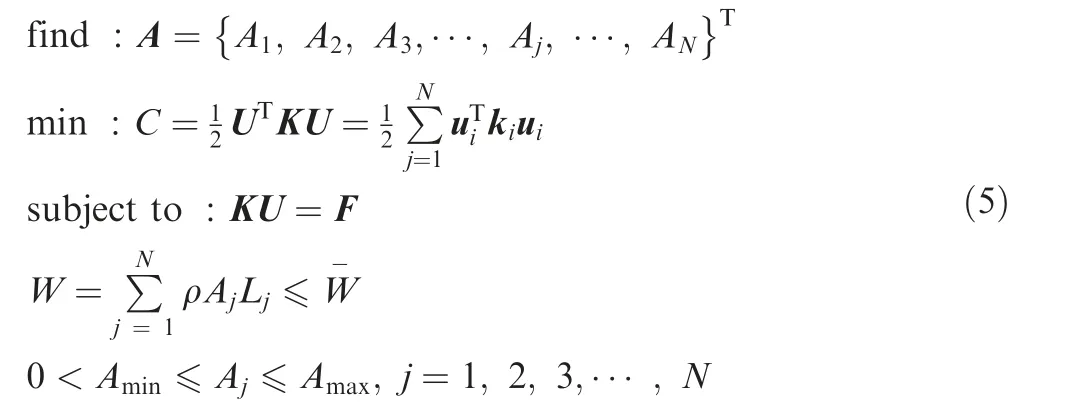

Fig. 3 Illustration of modeling method for lattice generation.
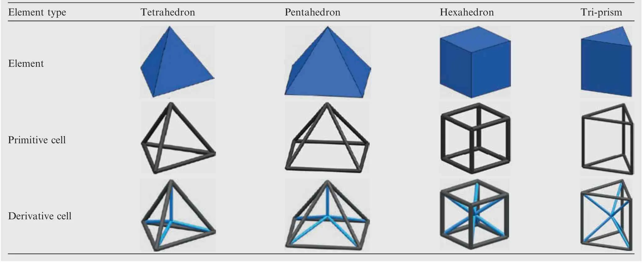
Table 1 Illustration of primitive and derivative lattice cells for different element types.
where Ajand Ljdenote the cross-section area and length of the j-th bar member in the lattice structures, respectively;W is the total weight of all bar members; N is the number of beam elements in the design domain;ρ denotes the density of the material;represents the mass constraint;Amin and Amax are the lower and upper bounds of the design variables Aj, respectively. For a 3D beam element in the local coordinate system,its element stiffness matrix k can be written as
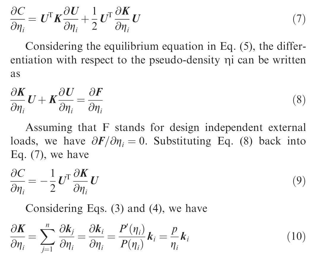
By substituting Eq.(10)back into Eq.(9),the sensitivity of the structural compliance with respect to the pseudo-density ηican be simplified as

where Ceiis the compliance of the i-th element.
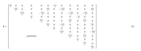
where E and G are the Young’s modulus and shear modulus,respectively; J is the torsional moment of inertia; Iyand Izare the cross-sectional moment of inertia in the xz-plane and xy-plane, respectively.
3. Sensitivity analysis
To solve the optimization problems in Eqs.(2) and (5) using gradient-based optimization algorithms, it is an essential prerequisite to obtain the sensitivities of the objective functions with respect to the design variables.
Considering the overall compliance C,its first-order derivative to the pseudo-density ηican be expressed as
Similarly, the sensitivity of the structural compliance with respect to the cross-section area variable Ajcan be expressed as

where the term ∂kj/∂Ajcan be easily derived from Eq. (6).
The sensitivities of the material volume V with respect to the pseudo-density ηican be expressed as

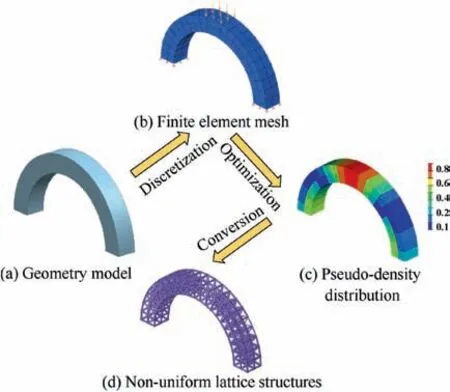
Fig. 4 Illustration of non-uniform lattice structures generation.
Besides,the sensitivities of the structure weight with respect to the cross-section area variable Ajcan be expressed as

Now, we have established mathematical formulations for the multi-scale optimization problem and deduced sensitivity formulas of the objective and constraint functions with respect to the design variables. To facilitate the understanding of the process of numerical implementation, the flowchart of the multi-scale design method developed in this study is shown in Fig. 5.
4. Numerical implementation
4.1. A payload adapter structure design for satellite
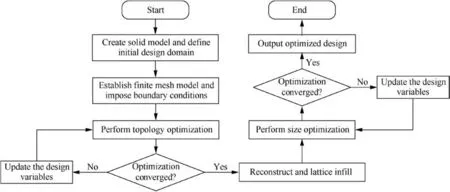
Fig. 5 Flowchart of proposed multi-scale design method for solid-lattice hybrid structures.
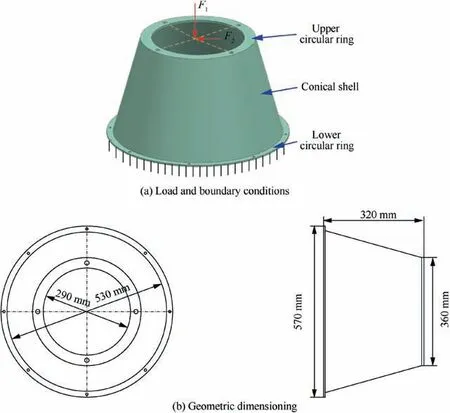
Fig. 6 A payload adapter structure with load and boundary conditions and geometric dimensioning.

Table 2 Properties of selected aluminum alloy.
To verify the proposed problem statement and the two-step optimization framework, the first numerical example considered here is a payload adapter structure,which plays an important role in connecting the satellite and the launch vehicle.The geometric features and dimensions of the payload adapter structure are illustrated in Fig. 6. Additionally, the thickness of the conical shell is 10 mm, and the thicknesses of the upper circular ring and the lower circular ring are 8 mm and 5 mm,respectively.There are four bolt holes with diameter of 12 mm on the upper circular ring and eight bolt holes with diameter of 8 mm on the lower circular ring. To save computational cost and guarantee high-quality grid model, these tiny bolt holes are ignored during the process of establishing the finite element model. The bottom surface of the lower circular ring is clamped, and two concentrated forces F1=16 kN and F2=4 kN are respectively applied at the center of the upper circular ring along vertical and horizontal directions. It is assumed that a common aluminum alloy is used to manufacture the payload adapter structure. The essential properties of the aluminum alloy are listed in Table 2.
Initially,the classical topology optimization is performed to obtain a light-weight and high-performance initial design under a 30% volume fraction constraint. Fig. 7(a) shows the finite element model of the payload adapter structure, which is discretized into a mesh containing 9600 quadrilateral elements and 24240 hexahedron elements. The green part of the model is defined as the design domain and the rest parts are considered as the non-design domains. Afterwards, topology optimization has been carried out to hunt for the optimal material distribution.Fig.7(b)illustrates the optimized results obtained by topology optimization with a cyclic symmetry constraint.
To further obtain a solid-lattice hybrid payload adapter structure with better stiffness performance, the model is artificially divided into the solid part and lattice-infill part according to the distribution of pseudo-density values. High pseudo-density areas (ηi≥0.8) are kept as solid part and low pseudo-density areas (ηi<0.8) are converted into latticeinfill part. Note that the conversion process is not carried on strictly according to pseudo-density values. We also consider the effect of primary load carrying paths and make adjustments to some extend in this design case. Later on, size optimization is performed to obtain the optimal cross-section area of the lattice structures under prescribed load and boundary conditions. To ensure that the final design meets weight requirements, a mass constraint of 4.9 kg is introduced into the size optimization problem. The iteration curves of the objective function and mass constraint are plotted in Fig. 8.As illustrated in the figure, it takes 15 iterations to reach the convergence. Apparently, the total mass of the solid-lattice hybrid payload adapter structure decreases sharply before the first 4 iterations and then keeps declining slowly until it converges to the mass constraint of 4.88 kg. What is noteworthy is that it shaves 16% of the weight at the expense of only 6.1% of the structural stiffness after performing the lattice optimization. The design and optimization process of solidlattice hybrid payload adapter structure is illustrated in Fig. 9 at length.
Afterwards,the rebuilt solid-lattice hybrid payload adapter structure is analyzed under prescribed load and boundary conditions by numerical simulation. Fig. 10 shows the global deformation and von-Mises stress distribution of the payload adapter structure.The maximum deformation of this structure occurs on the inner edge of the upper circular ring as expected with a maximum value of 0.205 mm.From an overall perspective,the stress of the solid-lattice hybrid payload adapter structure is distributed fairly uniformly. The maximum von-Mises stress is 66.71 MPa occurring in the interface between solid elements and beam elements. Besides, the high stress is also located on the bracing pieces of the payload adapter structure,especially in the upper half part.
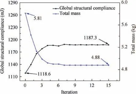
Fig.8 Iteration curves of objective function and mass constraint(of solid-lattice hybrid payload adapter structure).
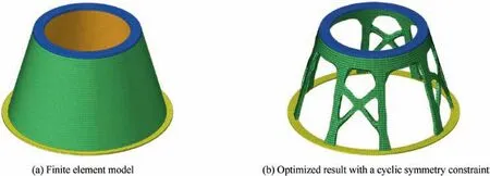
Fig. 7 Topology optimization of payload adapter structure.

Fig. 9 Design and optimization process of solid-lattice hybrid payload adapter structure.
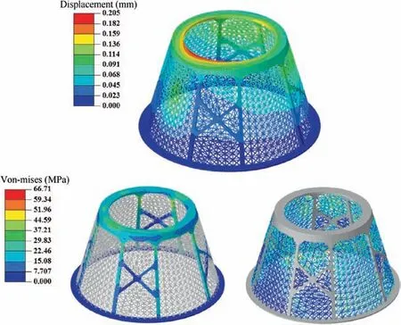
Fig. 10 Global deformation and von-Mises stress distribution of optimized solid-lattice hybrid payload adapter structure.
The solid-lattice hybrid payload adapter structure is further simulated with modal analysis using finite element method.Considering the actual working conditions,the modal analysis is carried out with bottom surface clamped and top surface connected with a satellite, whose weight is about 120 kg. Its first three natural frequencies and vibration modes are presented in Fig.11.It can be seen that the first three natural frequencies are 86.6 Hz, 98.6 Hz and 158.9 Hz, respectively.Apparently, the first two vibration modes of the structure are transverse deformation patterns while the third vibration mode is axial deformation pattern.

Fig 11 Vibration modes of optimized solid-lattice hybrid payload adapter structure.
4.2. A rudder structure design for hypersonic vehicle
To further verify the effectiveness and superiority of the proposed method, a typical trapezoidal rudder structure with a single connecting shaft is taken as the second numerical example. The geometric configuration and boundary dimensions of the rudder structure are illustrated in Fig. 12. The rudder structure is built by sweeping through the cross-section profiles of the front-end face and the aft-end face. Due to the good symmetry in geometric morphology, only half of the rudder structure is considered as the design object.The base thickness of the skin and the width of the frame around the rudder are 1 mm and 8 mm, respectively. The rest part of the rudder structure is considered as the design domain.A uniformly distributed aerodynamic pressure p=0.05 MPa is applied on the surfaces of the rudder structure.The surface of the connecting shaft is fixed as the boundary condition. It is assumed that nickel-based high-temperature alloy is used to manufacture the rudder structures. The material properties are posted in Table 3.
To obtain a light-weight and high-performance initial design,a classical topology optimization based on SIMP interpolation model is performed for minimizing compliance with a 30% volume fraction constraint. Fig. 13 illustrates the optimized result, where the structural topology displays the distribution of the tree-like branches. In order to transform optimized result into practical engineering structure, a standard reconstruction procedure is carried out according to the distribution of the tree-like branches, but tiny details are ignored. The rebuilt solid rudder structure is shown in Fig. 13. And its total weight is 2.226 kg.
Afterwards, the rebuilt solid rudder structure is analyzed under the uniformly distributed aerodynamic pressure. Theglobal deformation and von-Mises stress distribution of the rudder structure are illustrated in Fig. 14. On the whole, the deformation of the trailing edge is slightly larger than that of the leading edge according to the displacement contour, and the maximum displacement is 1.328 mm at the front tip of the trailing edge. It clearly indicates the superior stiffness of the leading-edge part over the trailing-edge part. Consequently, it is essential to balance the stiffness of different regions in further structural optimization. According to the stress contour, the high stress is mainly located at the root of the rudder,and there is less stress on the trailing edge. The maximum von-Mises stress is 215.1 MPa near the connecting shaft.

Table 3 Properties of selected nickel-based high-temperature alloy.
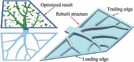
Fig.13 Optimized result obtained by topology optimization and rebuilt solid rudder structure.
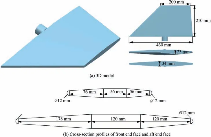
Fig. 12 A trapezoidal rudder structure and its boundary dimensions.

Fig. 15 Vibration modes of optimized solid rudder structure.
The rebuilt solid rudder structure is further simulated with modal analysis using finite element method. Its first three natural frequencies and vibration modes are presented in Fig. 15.It can be seen that the first three natural frequencies are 253.8 Hz, 345.8 Hz and 492.2 Hz, respectively. Additionally,the first two vibration modes are out-plane bending deformation patterns while the third vibration mode is in-plane bending deformation pattern.
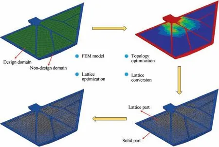
Fig. 16 Design and optimization process of solid-lattice hybrid rudder structure.
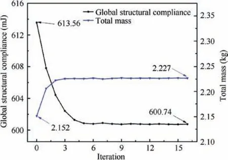
Fig. 17 Iteration curves of objective function and mass constraint (of solid-lattice hybrid rudder structure).
Furthermore, to obtain a solid-lattice hybrid rudder structure with better stiffness performance, the proposed multiscale design method is implemented with the same loads and boundary conditions. The design and optimization process of the solid-lattice hybrid rudder structure is systematically illustrated in Fig. 16. Initially, we identify the primary load carrying paths according to the topologically optimized results shown in Fig.13 and reconstruct the core structures using fine ribs. The skin, the frame and the ribs of the rudder structure are defined as the non-design domain and the rest part is defined as the design domain. And then a classical densitybased topology optimization is carried out to find the optimal material layout.Afterwards,the elements of design domain are converted into the lattice structures according to the distribution of pseudo-density values. Later on, size optimization is performed to obtain the optimal cross-section area of the lattice structures under prescribed load and boundary conditions.To ensure that the final design has identical material volume with the solid rudder structure,a mass constraint is introduced into the size optimization problem.The iteration curves of the objective function and mass constraint are plotted in Fig. 17.As illustrated in the figure, it takes 16 iterations to reach the convergence. Apparently, the global structural compliance decreases sharply before the first 5 iterations and then keeps declining slowly until it converges to 600.74 mJ. Therefore,the stiffness of the rudder structure is enhanced to some extend after lattice optimization. The final solid-lattice hybrid rudder structure is shown in Fig. 16.
Then the optimized solid-lattice hybrid rudder structure is analyzed under the uniformly distributed aerodynamic pressure. Fig. 18 shows the global deformation and von-Mises stress distribution of the rudder structure. The maximum deformation of this structure occurs at the front tip of the trailing edge as expected with a maximum value of 1.058 mm.From an overall perspective, the deformation of the trailing edge is slightly larger than that of the leading edge according to the displacement contour. As with the solid rudder structure, the high stress is also mainly located at the root of the rudder, and there is less stress on the trailing and leading edges.The maximum von-Mises stress is 212.7 MPa occurring on the connecting shaft, which is due to the stress concentration caused by the sharp corner. Nevertheless, the stress in the lattice structure region is distributed fairly uniformly.
Similar as the solid rudder structure, the optimized solidlattice hybrid rudder structure is further simulated with modal analysis using finite element method.Its first three natural frequencies and vibration modes are presented in Fig. 19. It can be seen that the first three natural frequencies are 291.4 Hz,386.4 Hz and 511.4 Hz, respectively. Different from the solid rudder structure, the first three vibration modes of the solidlattice hybrid rudder structure are all out-plane bending deformation patterns.
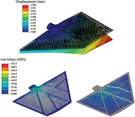
Fig. 18 Global deformation (scale factor is 50) and von-Mises stress distribution of optimized solid-lattice hybrid rudder structure.

Fig. 19 Vibration modes of optimized solid-lattice hybrid rudder structure.

Table 4 Comparison of three different designs for rudder structure.
To have a clearer comparison, three typical designs for the rudder structure and their performance are listed in Table 4.Obviously, the solid-lattice hybrid design has almost identical material volume with the solid design and the lattice design.However,the maximum deformation of the solid-lattice hybrid design is only 1.058 mm, which is 20.3% lower than the solid design and 55.5% lower than the lattice design. The smaller deformation value indicates the more superior stiffness of the structure. The maximum von-Mises stress in the solid-lattice design is subequal to the solid design, while it is 53.6% lower than the lattice design. Meanwhile, the solid-lattice hybrid design has the highest first-order modal frequency, approximately 14.8%and 49.8%higher than the solid design and lattice design, respectively. The significant improvements in the stiffness and first-order modal frequency clearly demonstrate the validity of the proposed multi-scale design method for solid-lattice hybrid structures.
5. Conclusions
This paper presented a new multi-scale design approach for the solid-lattice hybrid structures by integrating topology optimization and lattice-based optimization. The innovative solid-lattice hybrid designs with better performance were obtained by a normalized two-step procedure in this study.Moreover, two practical examples were presented to demonstrate the validity and advantages of the proposed method.Compared with the pure solid design and pure lattice design,the performance of the solid-lattice hybrid design was significantly improved. The maximum deformation of the solidlattice hybrid design is approximately 20.3% lower than that of the solid design and 55.5% lower than that of the lattice design.Meanwhile,the solid-lattice hybrid design has the highest first-order modal frequency, approximately 14.8% and 49.8% higher than the solid design and lattice design, respectively. The experimental results confirm beyond question that the solid-lattice hybrid design can significantly improve the stiffness and natural frequency compared with the pure solid design or pure lattice design.
Generally, structural designers carry out size optimization or topology optimization to improve the structural performance or reduce the structural weight at best. Furthermore,as a means of significant performance enhancement, the proposed multi-scale design method for solid-lattice hybrid structures is expected to provide new opportunities for the development of next-generation light-weight and highperformance aerospace vehicle components.
Declaration of Competing Interest
The authors declare that they have no known competing financial interests or personal relationships that could have appeared to influence the work reported in this paper.
Acknowledgements
This work is supported by National Key Research and Development Program (No. 2017YFB1102800), Key Project of NSFC (Nos. 51790171 and 51761145111) and NSFC for Excellent Young Scholars (No. 11722219).
 CHINESE JOURNAL OF AERONAUTICS2021年5期
- CHINESE JOURNAL OF AERONAUTICS的其它文章
- Ferrofluid moving thin films for active flow control
- Preliminary study on heat flux measurement data of TT-0 flight test
- An analysis and enhanced proposal of atmospheric boundary layer wind modelling techniques for automation of air traffic management
- Jet sweeping angle control by fluidic oscillators with master-slave designs
- Hot deformation behavior and microstructure evolution of the laser solid formed TC4 titanium alloy
- Electrochemical trepanning with an auxiliary electrode
