Integrated design of topology and material for composite morphing trailing edge based compliant mechanism
Xinxing TONG, Wenjie GE, Zhenyi YUAN, Djing GAO, Xinqin GAO
a School of Mechanical and Precision Instrument Engineering, Xi’an University of Technology, Xi’an 710048, China b School of Mechanical Engineering, Northwestern Polytechnical University, Xi’an 710072, China
KEYWORDS Compliant mechanism;Composites laminated plates;Fiber angles optimization;Morphing trailing edge;Topology optimization
Abstract The morphing trailing edge based compliant mechanism is a developing technology which can increase lift-drag ratio for variable flight modes by bending down the trailing edge.Composite material design is integrated into topology optimization for the morphing trailing edge based compliant mechanism in the paper.A two-step optimization strategy is established to solve the integrated design problem. Initially, lamination parameters are introduced and viewed as a bridge between structure stiffness and fiber angles for composite material. Design variables include the lamination parameters and element density.The least-squares between actual and desired displacements at output points along trailing edge is adopted to evaluate the deformed capability of the trailing edge. An integrated optimization model for the composite morphing trailing edge is established with the volume constraints.The optimal topologic shape and lamination parameters are initially obtained. Subsequently, a least-squares optimization between fiber angles and the optimal lamination parameters is implemented to obtain optimal fiber angles.Finally, morphing capability of composites trailing edge based compliant mechanism is investigated by simulation and experiments. The results indicate the composites trailing edge based compliant mechanism can approximately bend down 8 degrees and satisfies the design requirement.
1. Introduction
Morphing camber of trailing edge which can obviously increase lift-drag ratio for variable flight modes with deflexed trailing edge is an important form for the intelligent morphing wing.1-3Generally, the deflexed trailing edge can be implemented using link mechanisms or smart materials. However,more weight and discontinuous wing surface from link mechanisms,small displacement from smart material seriously inhibit the future development for morphing trailing edge.4-6In virtue of self-material elastic deformation,compliant mechanism can achieve the purpose of transmitting the motion,force or energy which have been largely reported.7,8The morphing process of the trailing edge based compliant mechanism is continuous and smooth.9Moreover, lighter weight, simpler structure and no hinge have been attracted attention in intelligent morphing wing.
The Air Force Research Laboratory (AFRL) and FlexSys are leaders in the design and application for morphing camber wings based compliant mechanisms. Compliant mechanism was firstly employed to design the morphing wing by the AFRL in 1998.10The results indicated that morphing wing based compliant mechanism can increase 51% in lift to drag ratio and 25% in lift coefficient at the 6-degree angle of attack by the wind tunnel test. Afterward, Lu et al. and Podugu et al. developed a universal methodology of compliant mechanisms, fabricated and tested morphing leading and trailing edges based compliant mechanism.11-13In 2014,FlexSys achieved adaptive seamless bending flap and tested in the Gulfstream 3 aircraft. The EU proposed the FP7-NOVMOR project for developing intelligent morphing wings based compliant mechanism.14,15According to the bend and aerodynamic force of morphing wing, the capacities of load-carrying and deformation are necessary to design compliant mechanism. However, Yin and Ananthasuresh16indicated that existing compliant mechanisms manufactured with isotropic material have serious contradiction between deformation and stress. In advantage of outstanding anisotropy, light weight and designability, composite material is considered as good candidate and become the hot issues of morphing wing.
Design and optimization of composites trailing edge based compliant mechanism is still in developing stage. Li et al.17proposed a topology optimization method of compliant mechanisms with composite laminated plates using the density method and provided technological base for designing morphing trailing edge. Tong et al.18,19seriously investigated the topology optimization methods for designing compliant mechanisms with laminated plates laid by linear and curve fiber.The results indicated that fiber angles can influence the topologic shapes, displacement and stress. Moreover, authors firstly investigated topology optimization of composite leading edge based compliant mechanism. Experiment indicated that the composite leading edge based compliant mechanism can arrive at the bend shape under external force.20The development of 3D printing has provided manufacturing conditions for the composite leading edge with curvilinear fiber. Xia and Shi proposed the a cascadic multilevel optimization algorithm for the design of composite structures with curvilinear fiber based on Shepard interpolation.21By virtue of the mature technology and low manufacturing cost, composite laminated plates with straight fiber are more favored by engineers. In current reports, topology optimization of composite trailing edges based compliant mechanism are based on a fact that fiber angles are constant and predefined by intuition.As is well known, mechanical performances of composite can be remarkably influenced by fiber angles.How to integrating optimization of fiber angles and topology is a big challenge to design trailing edge based compliant mechanism.22It can further enhance deformation capability of composite trailing edge.
In order to achieve optimal design of composite trailing edge based compliant mechanism,optimization of fiber angles and topology optimization of trailing edge are integrated in the paper. Fiber orientation and density are usually defined as design variables. According to constitutive relations and trigonometric function, structural response to the density is a power function and monotonous, while structural response to the fiber orientation variable is trigonometric function and non-monotonous. Integrated optimization problem involves the monotonous and non-monotonous behaviors simultaneously. Bruyneel et al. indicated that usually directly optimization strategy has poor convergence properties or even fail to solve the integrated problems.23Lamination parameters,which built a bridge between mechanism stiffness and fiber angles for composite material,and element density are defined as design variables. An optimization design method of integrating fiber angles and topologic shape for composite morphing trailing edge based compliant mechanism is proposed in the paper. A two-step optimization strategy is introduced to solve the simultaneous design to obtain optimal fiber angles and trailing edge simultaneously. The corresponding composite trailing edge and experiments are manufactured and implemented for demonstrating morphing capability of composite trailing edge.
The remainder of this paper is organized as follows.Section 2 describes design problem and boundary conditions of the composite trailing edge. The definition of lamination parameters, simultaneous optimization model and solution strategy are illustrated in Section 3. The optimal angles and topology shape of composite trailing edge are obtained and deformation experiments are investigated in Section 4. The conclusions are presented in Section 5.
2. Description of composite trailing edge based compliant mechanism
Topology optimization problem of the composite trailing edge based compliant mechanism will be described in this section.A schematic figure of morphing trailing edge,in which wing profile is assumed as the NACA2412 with a chord length c=400 mm,is shown in Fig.1.Spanwise space between adjacent ribs is assumed as L=200 mm and the total thickness of composite ribs is h=1.6 mm.The ribs are manufactured with composite laminated plates and modulus in single layer are assumed as E1=39 GPa, E2=8.4 GPa, G12=4.2 GPa,and Poisson’s ratio μ12=0.26.24The trailing edge domain accounts for 20%of the rib(c/5=80 mm)which will be filled with the compliant mechanism for bearing loads and generating desired deformation with actuator.So,the 20%domain in rib is defined as initial design domain of compliant mechanism.
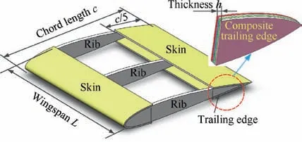
Fig. 1 A structural diagram of morphing wing including three ribs.
Optimization conditions of the composite trailing edge based compliant mechanism are shown in Fig. 2. One end of straight line AB is fixed and another is connected with spring Ks. Its stiffness is not only used to simulate the reactive force,but also can make the endpoint B to slide horizontally. External driving force F is imposed at midpoint of straight line AB.When shape of the trailing edge is deformed, magnitude and direction of the aerodynamic load will change as the structure deforms. This is a very complex nonlinear problem and difficult to solve. Designed deformed shape of the trailing edge in this paper is that the trailing edge bends downward 8 degree.At this time, magnitude of the aerodynamic load is maximal than other conditions according the flow simulation. For simplification, maximal aerodynamic load is considered as the boundary conditions of the trailing edge in topology optimization. Therefore, aerodynamic load from the skin is simulated and calculated under the air speed Ma=0.5,8 degree of bend down and 0 degree of attack angle.The aerodynamic loads are equivalent with concentrated forces evenly distributed in trailing edge and shown in Fig. 2(a).
Desired deformed shape and design domain of composite trailing edge based compliant mechanism are shown in Fig. 2(b). Making the trailing edge to bend down angle of 8 degree under actuator is desired design shape. The output points are evenly distributed in trailing edge and overlapped with aerodynamic forces. The weight factor αiis employed to estimate the influence of desired displacements in ith output points. Its value is proportional to the desired displacement. The bigger desired output displacement, the more weight factor. The weight factors, desired displacements and concentrated forces in output point are listed in Table 1.
3. Simultaneous optimization of the trailing edge
3.1. Laminations parameters
Lamination parameterization can reduce design variables regardless of number of total layers which were generally used to optimize fiber paths for various composite laminated plates.25,26According to the composite classic lamination theory, the in-plane lamination parameters vector V is defined with non-dimensional integration of angles in single layer along the thickness h direction and expressed as27
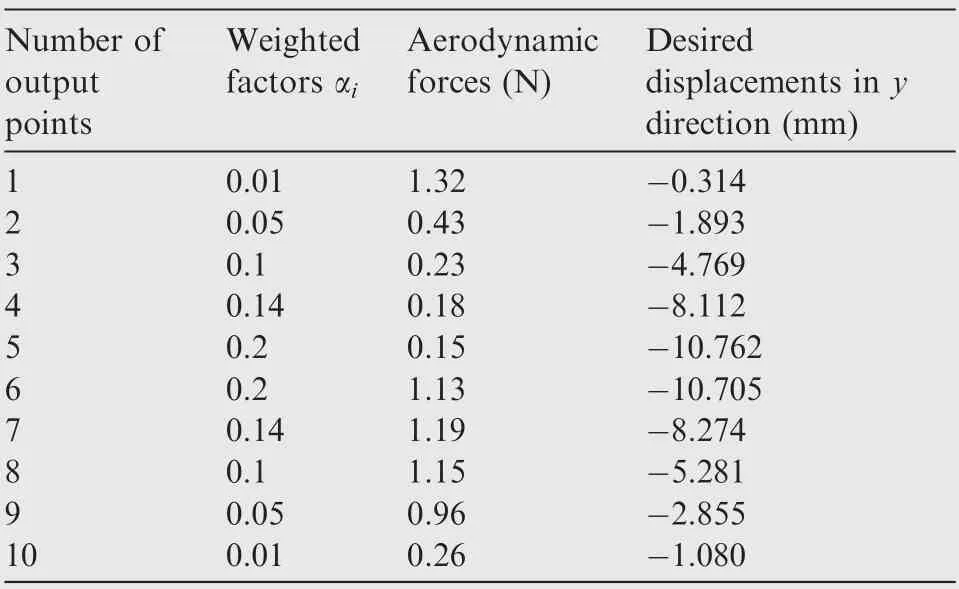
Table 1 Weight factors, desired displacements and concentrated forces in output point of trailing edge.

Whatever the actual number of total layers, the in-plane stiffness matrix A can be entirely parameterized with only four lamination parameters, which can be simply defined as linear function of the material invariants and expressed as28
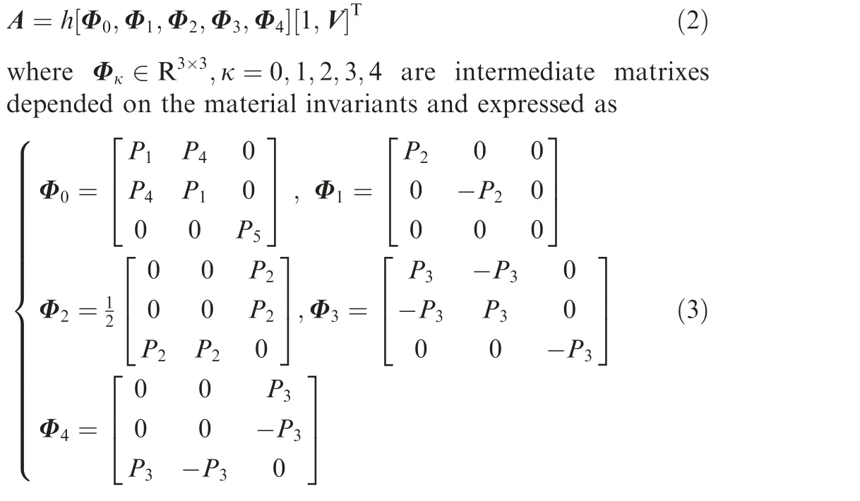
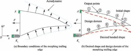
Fig. 2 Optimization conditions of composite trailing edge based compliant mechanism.
where Pe(e=1,2,3,4,5) are constant and named as material invariants, which are related to the material constants E1,E2, G12and Poisson ratio μ12.
Since the trigonometric functions in Eq.(1)are inter-related with each other, lamination parameters cannot be arbitrarily chosen. Consequently, the feasible region of in-plane lamination parameters is expressed as29

For the balanced symmetric laminated plates, lamination parameters V2=V4=0, the feasible region is simplified as

3.2. Optimization model
In order to achieve the optimal design for the composite trailing edge,optimizations of fiber angles and topologic shape are integrated. The initial design domain of the trailing edge is firstly discretized. Element relative density and lamination parameters are considered as design variables. In terms of self-material elastic deformation,trailing edge based compliant mechanism can generate bending deformation from its initial shape to desired shape under input force. The objective function of integrating optimization can be established using the weighted least-squares method and expressed as
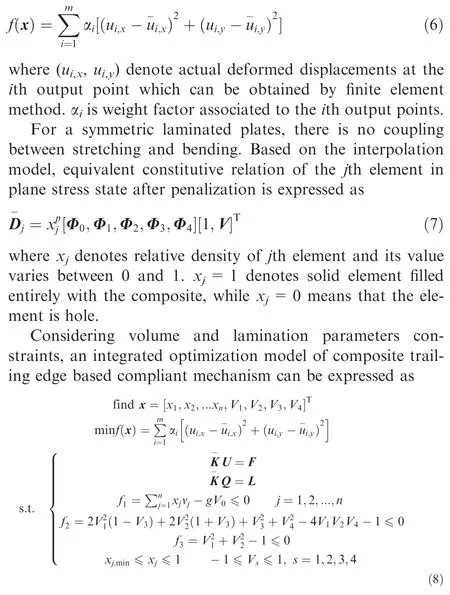
where x denotes design variable vector included elemental density and lamination parameters. The global displacement vector U and adjoint displacement vector Q can be respectively obtained by the finite element method under the actual external force F and adjoint load L. xj,minis the minimal limit and generally defined as 0.001.
3.3. Sensitivity analysis
For a symmetric laminated plates, the jth element stiffness matrix after penalization based on the Eq. (7) is expressed as
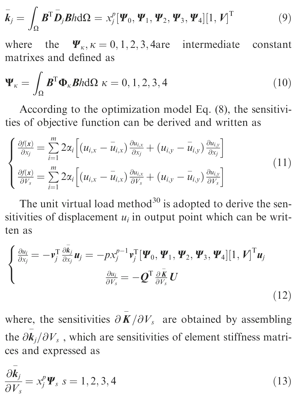
From the above,sensitivities of objective function to design variable can be achieved by substituting the Eqs.(13)and(12)into the Eq. (11).
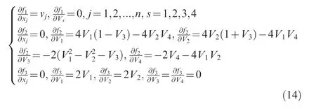
Since the volume constraint f1does not include the lamination parameters, the sensitivities of constraint functions f1, f2,f3to design variable are derived as
3.4. Obtaining fiber angle from optimal lamination parameters
By solving the above optimization model (Eq. (8)), optimal lamination parameters are obtained and named as vector V*
which is considered as constant to match with unknown fiber angles in this section.Based on the Eq.(1),the necessary relationship in constant V*and unknown fiber angles for symmetric laminated plates is established and expressed as

where t denotes the total number of independent fiber angles; θiis independent unknown fiber angle. It is generally difficult to directly solve the above nonlinear equations.Therefore, a least squares optimization problem for obtaining optimal fiber angles is built and described as

By solving the optimization model using the GCMMA,optimal independent fiber angles can be obtained. Since the symmetric laminated plates, remainder is equal with the independent fiber angles.
3.5. Solution strategy
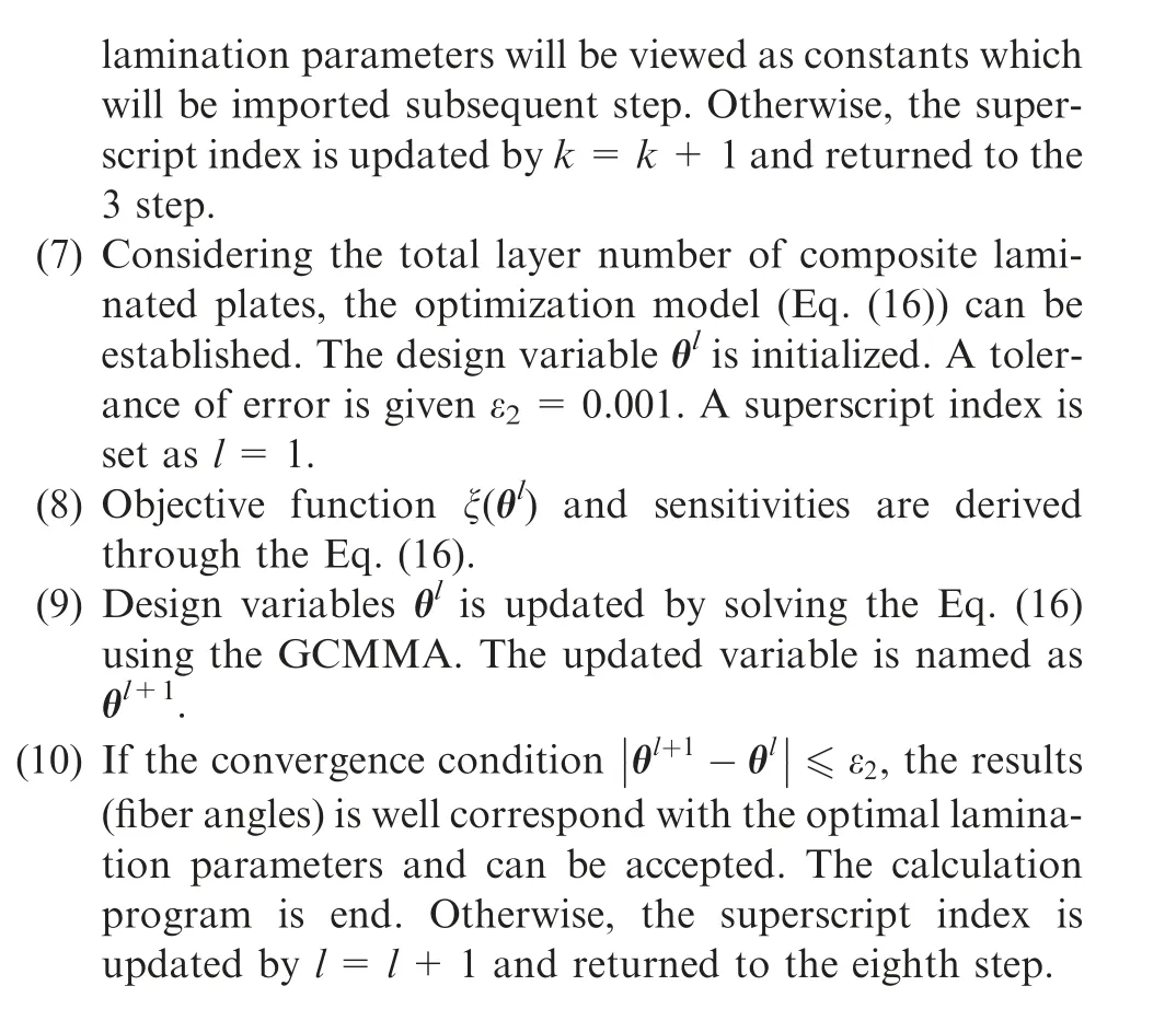
In this paper,fiber angles optimization and topology optimization are integrated for composite trailing edge based compliant mechanism. Optimal topology shape and lamination parameters for composite trailing edge are firstly achieved simultaneously by solving the design model (Eq. (8)). Subsequently, the optimal lamination parameters are viewed as constants and input into next optimization.By solving the least squares problem(Eq.(16)),optimal fiber angles corresponded with optimal lamination parameters can be obtained. Fig.3 shows the optimization process figure for the integrated design in which detailed steps are as follows:
(1) Design domain of complaint mechanism, desired bending shape, aerodynamic forces and weighted factors for trailing edge are firstly defined.
(2) The design domain of composite trailing edge is discretized with quad meshes by the ANSYS.Element density and lamination parameters are defined as design variables and included in the vector xk.A limiting value of error is defined as ε1=0.001 and a superscript index is set as k=1.
(3) The displacements at the 10 output points along trailing edge can be achieved by the FEM in Matlab. Subsequently, objective function and sensitivity are derived using the Eqs. (6) and (11).
(4) Filter technology can make the topology shape of trailing edge more clear by the smoothing the sensitivities of objective and constraint functions.

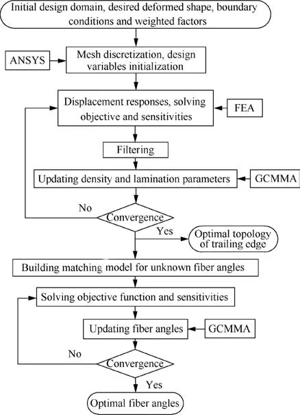
Fig. 3 Process diagram of solving integrated optimization problem.
4. Results and experiments
The composite trailing edge based compliant mechanism is made of glass fiber reinforced epoxy laminated plates. The driving force and spring stiffness are defined as F=20 N and η=3 N/mm, respectively. The desired volume ratio after optimization is assumed as g=40%.The density and lamination parameters are respectively initialized and set as x=0.4 and V1=V2=0.25, V3=V4=-0.75. The weight factors α in optimization process are constant and their values have been listed in Table 1.
4.1. Optimization process
Using the proposed method,optimization results of composite trailing edge based compliant mechanism are shown in Fig. 4.It is clear to see that the values of objective and volume ratio gradually stabilize and the values are 0.392 and 39.985%,respectively. The results indicate that actual displacements at the output points and volume ratio for trailing edge approximately satisfy the desired objective.
The iteration curves of lamination parameters (V1,V2,V3,V4) in optimization process for composite trailing edge with symmetric laminated plates are shown in Fig. 5. The results are stable convergence and the values are V1=0.971,V2=-0.189, V3=0.797 and V4=-0.364, respectively.The results imply that the optimization process is stable and converged using the method. The optimal lamination parameters will be defined as constants to optimize the independent fiber angles in next step.
The numbers of total layer for symmetric laminated plates are assumed as N=8 and N=12.Since symmetric laminated plates is employed,the numbers of independent unknown fiber angle are t=4 and t=6, respectively. Using the matching method from the Eq.(16),independent fiber angles for trialing edge with different total layers for symmetric laminated plates are obtained and listed in Table 2. The 0 degree fiber angle denotes along horizontal direction and positive rotation is counter clockwise. These optimal fiber angles are substituted into Eq.(15)for solving the new lamination parameters.When the total layers N=8, the new lamination parameters are V1new=0.949, V2new=-0.193, V3new=0.805, V4new=--0.361, respectively. Compared with the optimal lamination parameters obtained by the optimization method, value of maximal error is 2.4%. When the total layers N=12, the new lamination parameters are V1new=0.949, V2new=--0.196, V3new=0.804, V4new=-0.359, respectively. Compared with the optimal lamination parameters, value of maximal error is 3.7%. The results indicate that optimal fiber angles are well correspond with optimal lamination parameters by this method.
4.2. Deformation simulation
Assumption of the total layers N=8, based on the optimal fiber angles and topology shape, actual deformed shape of composite trailing edge based compliant mechanism under the external force F=20 N is analyzed and shown in Fig. 6.The green dot dash line and red dashed line respectively denote the initial and desired deformed shapes of trailing edge. It is clear to see that the actual deformed shape is approximately consistent with the desired shape. The actual displacements,desired displacements,errors and relative errors of the 10 output points are listed in Table 3.The maximal error is located at the 6th output point. Its value and relative error is 1.033 mm and 9.6%, respectively. The actual displacements at the 5th and 9th output points are-11.583 mm and-2.749 mm.Compared with the desired displacements, the errors are 0.821 mm and -0.106 mm, respectively.
In order to investigate the influences of the spring stiffness η on deformed shape of composite trailing edge, the drive force F=20 N is set as constant and variable spring stiffness are defined as η=2, 3,4 N/mm and 5 N/mm, respectively. Finite analysis model of composite trailing edge is generated by extracting the optimal topology shape shown in Fig. 4(a).The actual deformed shapes of trailing edge with different spring stiffness are simulated and shown in Fig. 7 using the ANSYS.Red dash line denotes the desired shape of composite trailing edge.
When the spring stiffness η=2 N/mm, no enough spring force resists the external drive force and the deformed curve exceeds the desired shape. When the spring stiffness η=5 N/mm, the spring displacement is smaller and the deformed curve is situated above the desired shape. When the stiffness η=3 N/mm, the deformed curve is approximately according with the desired shape. From the above,the spring stiffness is key factor to influence the whole deformed shape of composite trailing edge based compliant mechanism.When the spring stiffness is too flexible,deflection angle of the trailing edge is mainly caused by the spring deformation than the trailing edge deformation. Although deflection angle satisfies the design requirement, the deformed shape of the trailing edge is inconsistent with the desired shape.When the spring stiffness is too stiff,the deflection angle of the trailing edge is mainly caused by the topology shape. The deformed shape of the trailing edge is inconsistent with the desired shape.Therefore,the bending deflection of the trailing edge is realized by the topological shape deformation and the spring deformation simultaneously. The obtained optimal spring stiffness and the topology shape of trailing edge can ensure that the trailing edge achieves the desired deformed effect. The lower skin is sliding when the trailing edge is deformed.However,the sliding area is very small and the main aerodynamic loads are concentrated in the middle and front section of the trailing edge.The aerodynamic change in sliding area has little impact on the design results.
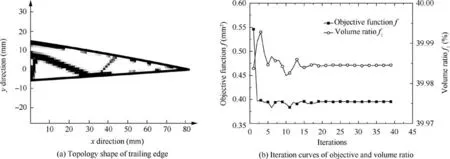
Fig. 4 Optimization results of composite trailing edge based compliant mechanism using proposed method.
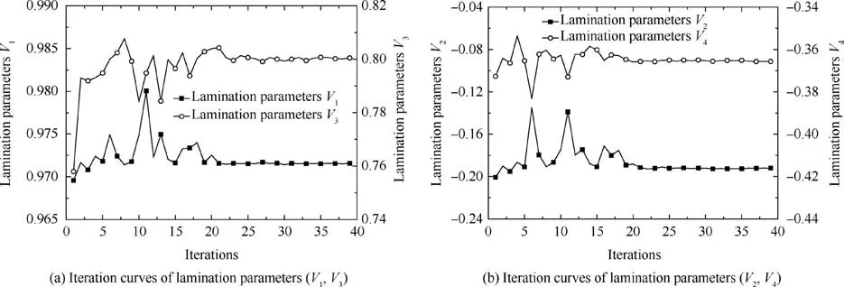
Fig. 5 Iteration curves of lamination parameters (V1,V2,V3,V4) in optimization process for composite trailing edge with symmetric laminated plates.

Table 2 Independent fiber angles of composite trailing edge with different total layers for symmetric laminated plates.
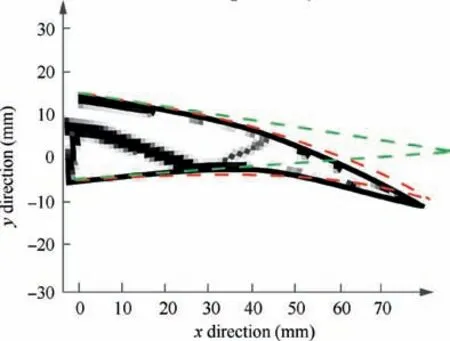
Fig. 6 Actual deformed shape of composite trailing edge based compliant mechanism under external force F=20 N.
4.3. Experiment analysis
Assumption of the total layers N=8, symmetric laminated plates is initially made of glass fiber reinforced epoxy based on the optimal fiber angles.Then,based on the topology shape shown in Fig.4(a),composite trailing edge is manufactured by laser machining. Installation schematic diagram of the partial morphing wing with the composite trailing edge is shown in Fig.8.The top edge of trailing edge is fixed with the main rear wing-spar. The lower edge is connected with the spring and slidable along the horizontal groove. Compliant ribs are key component to bend deformation and bear aerodynamic loads.In this section, deformed capability of the compliant ribs with composite is mainly investigated. Experiments of the whole morphing wing will be researched in future.For the composite trailing edge, experiment layout and actual deformed process of composite trailing edge based compliant mechanism are shown in Fig. 9. The spring stiffness is defined as η=3 N/mm and external force F=20 N. The left end of composite trailing edge is fixed and the right end is connected to the slider, which can vertically slide along the fixed block.
From the Fig.9,experimental deformed shape of composite trailing edge is consistent very well with the desired shape.The maximal displacement at the tip is 11 mm and according with the above simulation results.Experimental results indicate that composite trailing edge based compliant mechanism can bend down 8 degrees and satisfies the design requirements using the proposed method. Moreover, optimal topology shape and fiber angles of composite trailing edge can be obtained simultaneously.
In the integrated optimization process of topology and materials, the aerodynamic loads are considered as boundary conditions and participated in optimization calculation.Therefore, the obtained optimal topology shape and fiber orientations are effective in theoretical calculation. The deformed capability of the trailing edge also is verified by the Ansys simulation.Because of the difficulty for exactly applying the aerodynamic loads in trailing edge and the small magnitude ofaerodynamic loads, the aerodynamic load is ignored in the experiment. Deformed capability of the trailing edge with aerodynamic loads in experiment will be consistent with the results from the simulation. Aerodynamic loads may be replaced by concentrated constant forces in experiment in future.

Table 3 Actual displacements, desired displacements, errors and relative errors of 10 output points by ANSYS simulation.
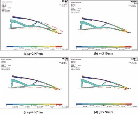
Fig. 7 Deformed shapes of composite trailing edge based compliant mechanism with different spring stiffness.
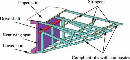
Fig. 8 Installation schematic diagram of partial morphing wing with composite trailing edge.
5. Conclusion
The optimization design of integrating fiber angles and topology for composite trailing edge based compliant mechanism is achieved. The deformed experiments are investigated to verify the availability of the design method.The main conclusions of the study are as follows:
(1) Taking the element relative density and lamination parameters as design variables, the optimization model of integrating lamination parameters and topology for composite trailing edge based compliant mechanism is built. Using the GCMMA, optimal topology shape and lamination parameters for composite trailing edge can be obtained simultaneously.
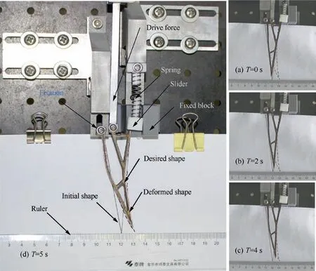
Fig. 9 Experiment layout and actual deformed process of composite trailing edge based compliant mechanism.
(2) For the symmetric laminated plates,optimal fiber angles are retrieved from the optimal lamination parameters by solving the optimization problem. The maximal errors for the total layers N=8 and N=12 respectively arrive at 2.4%and 3.7%,which verifies the effectiveness of the matching optimization method.(3) The composites trailing edge based compliant mechanism is manufactured and deformed experiments are investigated. The results indicate that composites trailing edge can bend down 8 degrees and approximately satisfies the design requirement. It illustrates the availability of the combining optimization method for composite trailing edge.
For future research, variable stiffness laminated plates(curve fiber paths) which have excellent mechanical properties will be used to manufacture the trailing edge. Therefore,simultaneous optimization of topology and fiber paths for trailing edge will be very interesting problem. Moreover,the proposed method is also adopted to the optimization problem on the honeycomb sandwich composites and multilayer composite. Although some well results were obtained in this paper, the deformed model was still based on the Kota’s method. New morphing structure according to the structural characteristics of the trailing edge will be explored in future.
Declaration of Competing Interest
The authors declare that they have no known competing financial interests or personal relationships that could have appeared to influence the work reported in this paper.
Acknowledgements
This study was co-supported by the National Natural Science Foundation of China (Nos. 51375383 and 51575443), Natural Science Foundation of Shaanxi Province of China (No.2019JQ-728) and Doctor’s Research Foundation of Xi’an University of Technology of China (No. 102-451118017).
 CHINESE JOURNAL OF AERONAUTICS2021年5期
- CHINESE JOURNAL OF AERONAUTICS的其它文章
- Ferrofluid moving thin films for active flow control
- Preliminary study on heat flux measurement data of TT-0 flight test
- An analysis and enhanced proposal of atmospheric boundary layer wind modelling techniques for automation of air traffic management
- Jet sweeping angle control by fluidic oscillators with master-slave designs
- Hot deformation behavior and microstructure evolution of the laser solid formed TC4 titanium alloy
- Electrochemical trepanning with an auxiliary electrode
