Effect of operational condition of rotational subsystem on attitude control for space solar power station
Xiangfei JI, Baoyan DUAN, Yiqun ZHANG,*, Guanheng FAN,Meng LI, Yang YANG
a Shaanxi Key Laboratory of Space Solar Power Station System, Xidian University, Xi’an 710071, China
b Key Laboratory of Electronic Equipment Structure Design Ministry of Education, Xidian University, Xi’an 710071, China
c Qian Xuesen Laboratory of Space Technology, China Academy of Space Technology, Beijing 100094, China
d School of Chemical Engineering, Northwest University, Xi’an 710071, China
KEYWORDS Space solar power station;SSPS-OMEGA;Kinematic analysis;Dynamic analysis;Attitude control system
Abstract Space Solar Power Station(SSPS) is a giant spacecraft to collect space solar energy and transmit electric energy to the ground by using the wireless transmission technology. As a concentrated space solar power station, SSPS via the Orb-shape Membrane Energy Gathering Array(OMEGA) system is comprised of the concentrator subsystem, the photovoltaic array subsystem and the transmitting antenna subsystem.In this manuscript, the comprehensive study on the coordinate kinematic among subsystems is carried out.Firstly,kinematic analysis and dynamic analysis are conducted. Secondly, under the condition of ideal attitude, the influence of the moving condition of the Photovoltaic (PV) array on the overall system is studied. Finally,the control ability for the deviation attitude caused by the acceleration process of the photovoltaic array is studied. The simulation results demonstrate the serious influence of the angular acceleration of the photovoltaic array on the system’s attitude and the validity of the designed attitude control system.
1. Introduction
Unlike the solar energy that reaches Earth, solar energy in Space has the advantages of long irradiation times,high energy flow density, and is not affected by climate.1,2Solar energy in Space is collected by the Space Solar Power Station(SSPS)and is converted into electricity. Subsequently, using wireless energy transmission technology(microwave or laser),the electricity is transmitted to the Earth. SSPS can provide clean energy for the Earth and reduce Earth’s dependence on fossil energy.
The first space solar power station scheme was proposed by Glaser,3and subsequently, the scholars put forward many innovative schemes, such as the integrated symmetric concentrator scheme,4sun tower configuration,5Tethered SSPS configuration,6SSPS reference system,7SSPS-ALPHA,8multirotary joints SSPS,9etc. Furthermore, Yang and Duan et al.10,11proposed a new design of the SSPS via the orbshape membrane energy gathering array(OMEGA).As shown in Fig. 1, the portion of SSPS-OMEGA in Space is mainly composed of three subsystems: the concentrator, Photovoltaic(PV) array, and the transmitting antenna. Because it is spherical,the concentrator does not need to track the Sun.Only the PV array is required to rotate inside the concentrator to be oriented to the Sun. Because of the concentrator reaching km scales to attain an output power of giga watt magnitude, the rotation range of the PV array is also huge. Wireless energy is transmitted to the rectenna on the surface of the Earth by the transmitting antenna placed in the path of the microwave.It is necessary to ensure a match between the footprints of the beam from the antenna and the rectenna.
Because of the large relative movement between subsystems, large-scale deviations in the working attitude of the SSPS-OMEGA would occur without valid control. Furthermore, this deviation in attitude will seriously affect the pointing accuracy of the transmitting antenna, and the rectenna would thus receive much less energy from the transmitting antenna. Meanwhile, the super-high power microwave beam is a great threat to people outside the receiving area on the Earth’s surface. Therefore, the problem of multi-subsystem collaborative design arises.12In the complex environment of Space,this problem is more prominent.To guide the structural design and the in-orbit assembly of the SSPS-OMEGA, the kinematic and dynamic analyses of the SSPS-OMEGA is particularly important.
As the largest spacecraft, the International Space Station(ISS) consists of several chambers. However, there is no relative motion between the chambers, and they can be viewed as one body when kinematic analysis and dynamic analysis are carried out.13In addition, the general satellite mostly consists of a primary rigid body, including the payload, and flexible additions such as the solar panels that have the freedom of a single degree of rotation with respect to the primary body.14-18However, it is a fixed axis rotation, which only has a single degree of freedom.
In the case of other SSPS systems, many researchers have carried out extensive kinematic and dynamic analysis. Wie and Roithmayh19built the attitude dynamic model of the SSPS reference system, which describes attitude motion law. In some cases, a low-bandwidth attitude control system was employed. McNally et al.20studied the orbital dynamic model of various SSPS for the geosynchronous Laplace plane. Jin et al.21and Meng et al.22successively planned the target movement for the integrated symmetric concentrator scheme, in order to uniformly focus energy on the photovoltaic cells. Furthermore, Meng considered the influence of the concentrator on the energy distribution after the splice. Liu et al.23studied the relationship between each of the parts of the Sun tower system while in motion, and established the orbit-attitude coupled dynamics model. The important novel point is the influence of the structural factor of the concentrator on the solar collection fluctuation for SSPS-OMEGA.24However, all the studies on the SSPS are still focused on vibration suppression, attitude control system design, and energy distribution in the PV cell, and not on the motion analysis of the rotational subsystem.
The gravity gradient torque equation applied on the PV array is derived for SSPS-OMEGA, and the attitude control system and the corresponding electric thruster configuration scheme are designed. In ideal situation, the PV array rotates around the concentrator at a uniform angular velocity.25However, the attitude of the PV array should be adjusted to track the Sun by adjusting its speed. Therefore, the work focuses on the effect of the operation situation of the PV array on the overall system’s dynamic response. In this research work,for the case of the SSPS-OMEGA, kinematic analysis and dynamic analysis are conducted. Furthermore, the influence of the moving condition of the PV array on the overall system attitude is studied. Finally, the attitude control system is designed, and the ability to control a deviant attitude caused by the acceleration of the PV array is studied.
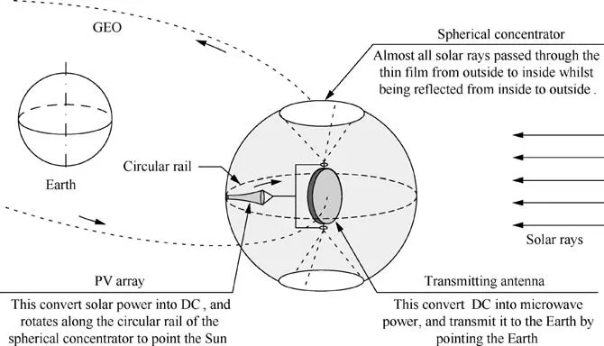
Fig. 1 SSPS-OMEGA configuration diagram.
2. Kinematic analysis
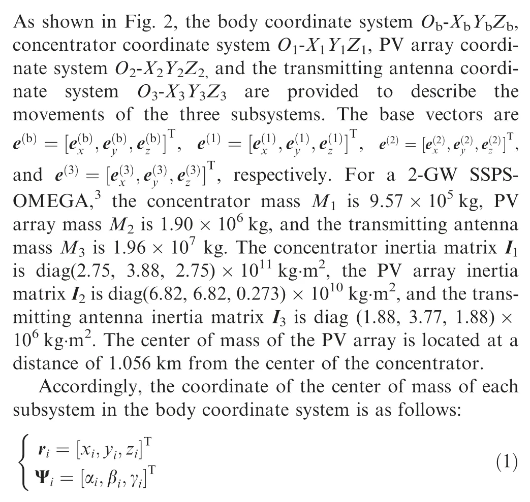
where riis the position vector of the center of mass of the ith subsystem with respect to the body coordinate system, and Ψiis the Cardano angle of the center of mass of the ith subsystem with respect to the body coordinate system.
As shown in Fig. 2, the origin Obof the body coordinate system moves along Geosynchronous Earth orbit (GEO), the PV array coordinate system rotates inside the concentrator around the Y1axis,and the Z2axis is anti-parallel to the direction vector of the solar ray. The Z3axis of the transmitting antenna coordinate system always points to the origin OEof the Earth’s inertial coordinate system. Therefore, the constraint equations are shown as follows:

where l2is the distance between the origin O2and the origin O1,and A(bi)is the direction cosine matrix of the ith coordinate system with respect to the body coordinate system, as follows:

where E3is the 3×3 identity matrix.

where Φ is the rotational angle of the PV array around the Y1axis.
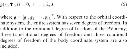
The constraint Eq.(2)contains 17 equations is written in its general form as follows:
3. Dynamic analysis
As depicted in Fig.3,the position vector of the center of mass of the ith subsystem with respect to the Earth’s inertial coordinate system is as follows:
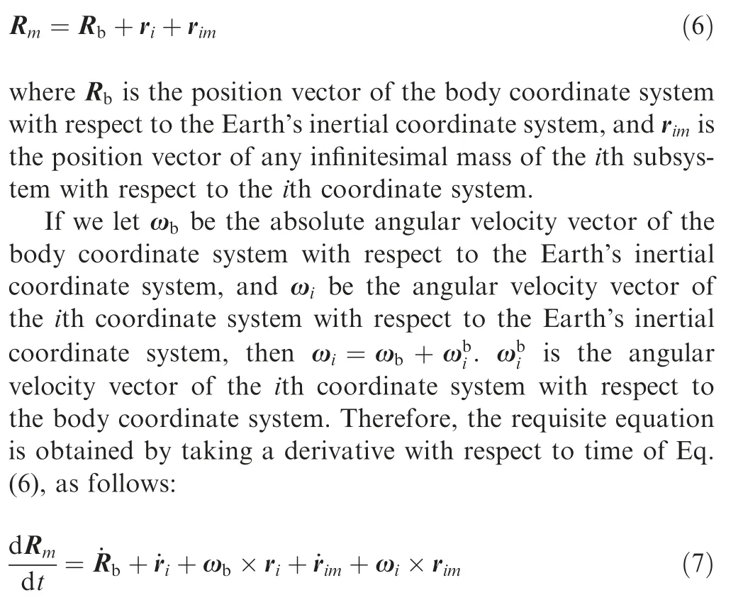
The linear momentum of the ith coordinate system is portrayed as follows:
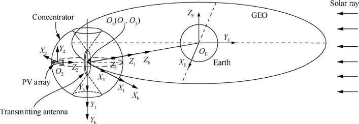
Fig. 2 Kinematic relationship among the three subsystems of SSPS-OMEGA.
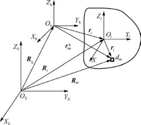
Fig. 3 Vector diagram of each coordinate system.

where Siis the ith subsystem. Because all the subsystems are considered as rigid bodies, and Oiis the center of mass of the ith subsystem,∫Sirimdm = 0, and ˙rim= 0. Eq. (8) can be further simplified as follows:
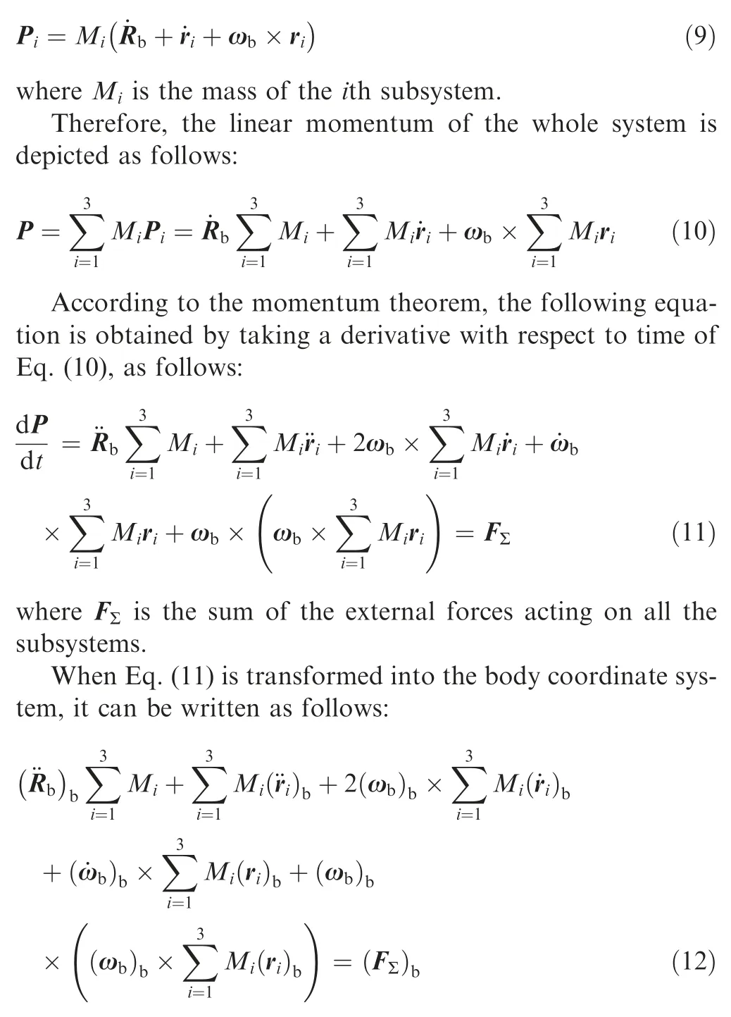
where (·)brepresents the component matrix of the vector in the body coordinate system.
The angular momentum of the ith subsystem with respect to the origin Obof the body coordinate system is represented as follows:
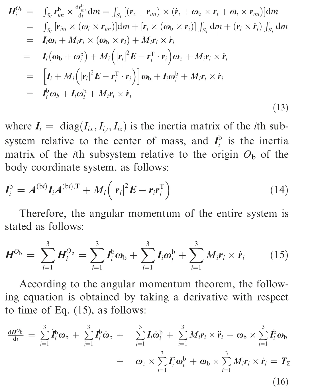
where TΣis the sum of the external torques acting on all the subsystems.
When Eq.(16)is transformed into the body coordinate system, it can be written as follows:
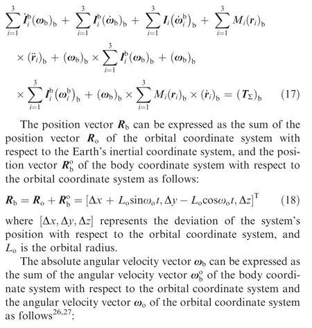
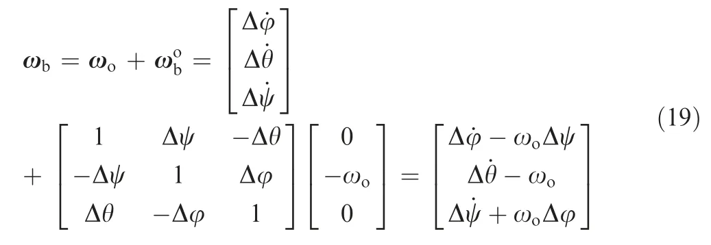
where [Δφ,Δθ,Δψ] is the attitude deviation angle in the direction of the roll,pitch,and yaw respectively,and ωois the orbital angular velocity.

The constraint Eq.(2)is substituted into Eqs.(12)and(17),and the two equations are combined and written in the form of a matrix as follows:where q = [Δx,Δy,Δz,Δφ,Δθ,Δψ]T,and H and G are the coefficient matrix or vector as follows (the element items not written are zero by default):
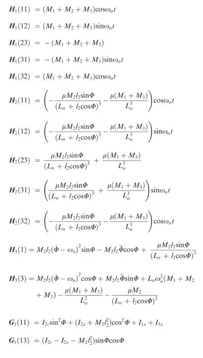

Meanwhile, Eq. (20) contains the mass Mi, the inertia Iiof each subsystem and the distance from the center of mass of the PV array to the center of the concentrator.Therefore,Eq.(20)can be used as the dynamic equation for the comprehensive optimal design of the system, and further, can be used as the theoretical basis for the design of the control system.
4. Effect of operating condition of PV array on attitude
Ideally, the PV array would always orient itself towards the Sun by rotating around the concentrator’s central axis. However, either because of a shortage of energy to drive the PV array rotation or during the initial operating attitude adjustment, the PV array needs to be adjusted via an appropriate acceleration, while it is accurately pointed towards the Sun.The adjustment will affect the attitude of the SSPS-OMEGA and will test the limits of the attitude control system. In order to study the influence of the acceleration process on the attitude of the whole system,four movement conditions are set for PV array. The accelerations are ¨Φ = 0, ¨Φ=1.0×10⁻⁵(°)/s2, ¨Φ=2.0×10⁻⁵(°)/s2, and ¨Φ =3.0×10⁻⁵(°)/s2respectively.In the absence of any control torque,the influence of the PV array’s operating conditions on the attitude deviation angle and the control torque required to maintain an ideal attitude are studied by taking the gravity gradient torque as the unique disturbing factor.
Because SSPS-OMEGA is symmetric about the ObXbZbplane, there is no attitude deviation angle in the roll and yaw directions when only the gravity gradient moment is considered as the external moment. The rotation of the PV array modifies the symmetric relationship of the system with respect to the ObYbZbplane periodically. Under the action of the gravity gradient torque, the attitude deviation angle in the pitch direction also changes correspondingly. As shown in Fig.4,under the uniform rotation condition,the attitude deviation angle of the system in the pitch direction varies periodically with a maximum of 155 °. When a small acceleration is applied to the PV array, the attitude deviation angle in the pitch direction increases substantially without any attitude control. Meanwhile, as the acceleration value increases, the attitude of the body coordinate system deviates more from the orbital coordinate system.
To ensure that the rectenna on the Earth’s surface can generate enough power, the transmitting antenna of the SSPSOMEGA needs to point precisely to the rectenna. Therefore,the attitude control system needs to continuously provide control torque to resist the attitude change of the system caused by the rotation of the PV array.It can be seen from Eq.(20)that in order to maintain an ideal attitude,that is,Δφ = 0,Δθ = 0,Δψ = 0, which are substituted into Eq. (17), the attitude control moment in the pitch direction gives:
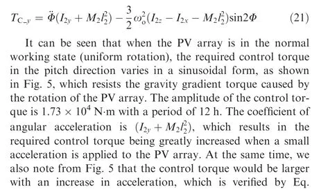
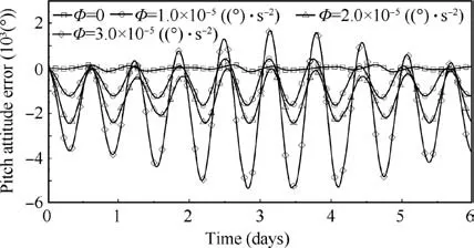
Fig. 4 Attitude deviation angle curve in pitch direction without control system.
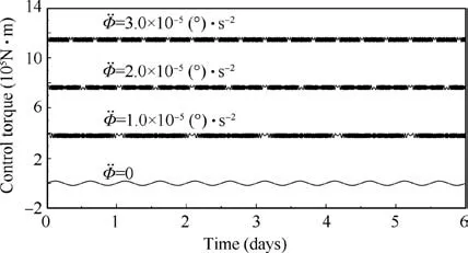
Fig. 5 Under the ideal attitude condition, torque curve in pitch direction.

5. Attitude control system design
To maintain the required attitude of the whole system while in operation, it is necessary to set up an attitude control system.The actuators of the control system can be realized by using distributed electric thrusters.25
5.1. Attitude controller design
As shown in Fig.6,electric thrusters are arranged at four positions where the Xbaxis and Zbaxis of the body coordinate system intersect the circular rail. At each position, there are four groups thrusters which the nozzles are perpendicular to each other and the direction is parallel to the coordinate axis of the body coordinate system. The control torque in roll direction is provided by the electric thrusters in the±Ybdirection at#2 and#4 positions.The control torque in pitch direction is provided by the electric thrusters in the±Zbdirection at #1 and#3 positions and in the±Xbdirection at#2 and#4 positions. The control torque in yaw direction is provided by the electric thrusters in the±Ybdirection at#1 and#3 positions.
Without orbital dynamics, the attitude dynamics equation in Eq. (20) is rewritten as follows:
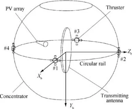
Fig. 6 Schematic diagram of electric thruster configuration scheme.
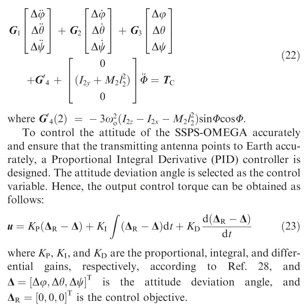
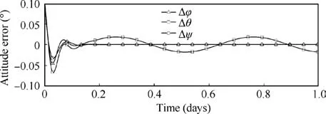
Fig.8 Attitude error with initial attitude deviation angle 0.1°in one day.
According to the error e=ΔR-Δ,the PID controller outputs instructions u and sends them to the electric thrust system,as shown in Fig.6,to provide actual control torque TCfor the SSPS-OMEGA.Meanwhile,in the time interval[t1, t2],the PV array accelerates uniformly, and subsequently, in the time interval [t2, t3], it decelerates uniformly. The influence of the operating condition of the PV array on the attitude control system is studied using its acceleration and deceleration motion. The diagram of the main control system structure is shown in Fig. 7.
5.2. Simulation results
In this section,simulation results are provided.The initial attitude deviation angle is[0.1°,0.1°,0.1°]T,and the attitude angular velocity is [0,0,0]T. At time t1, the PV array starts acceleration with an acceleration ¨Φ, and after time t2, it slows down with an acceleration -¨Φ. Finally, the PV array rotates around the concentrator uniformly after time t3. Set t1=1 day, t2-t1=0.5h, and t3-t1=1h. The angular acceleration of the PV array is set in three cases, that ¨Φ=1.0×10⁻⁵(°)/s2, ¨Φ=2.0×10⁻⁵(°)/s2, and ¨Φ=3.0×10⁻⁵(°)/s2.

Fig. 7 Attitude control system block diagram.
As shown in Fig.8,under the condition that the initial attitude deviation angle is 0.1°, the deviation attitude can be stabilized by the attitude control system within 5 h. The attitude in the roll and yaw direction is well controlled, and attitude deviation angle is controlled within 10-5(°). At this time, the PV array rotates uniformly around the pitch axis of the body coordinate system. Because of the influence of the gravity gradient torque,the attitude deviation angle varies periodically with a period of 12 h and an amplitude of 0.018°. Assuming that the PV array should not track the Sun and setting some different kinds of angular velocity,as shown in Fig.9,the pitch attitude error gives the different performance of amplitude and period. With the velocity growing, the amplitude of the pitch attitude error increases and the period decreases. When ˙Φ = 4ωo, the amplitude gets to 0.09° which would seriously affect the pointing accuracy of the transmitting antenna, and the error could not be eliminated by the attitude control system. Thus, the rotation of the PV array causes the SSPSOMEGA to swing around the pitch axis, which affects the pointing accuracy of the transmitting antenna towards Earth.If more precise directional requirement is needed, the capability of the transmitting antenna should be improved to facilitate easier and more accurate electronic adjustment.
As shown in Fig. 10, because of the acceleration of the PV array,the attitude deviation angle increases to a large degree in the pitch direction after t3, a serious deviation. When ¨Φ=1.0×10⁻⁵(°)/s2, the degree is 1.5°. When ¨Φ=2.0×10⁻⁵(°)/s2, it gets to 3.1°, and ¨Φ=3.0×10⁻⁵(°)/s2, it is 4.7°.To eliminate the deviation angle,the attitude controller would output great control torque, and more fuel would be consumed. Under the endeavor of control system, the pitch attitude error still changes in±0.018°. In the pitch direction, as the attitude deviation angle changes periodically, the periodic control torque is also required. The amplitude of the control torque is 1.73×10⁴N·m with a period of 12 h.
It can be seen from Eq. (22) that the angular acceleration term of the PV array only exists in the pitch direction. Therefore, the attitude in the roll and yaw directions is not affected beyond the stated limits,and the acceleration and deceleration process of the PV array only causes a deflection of the roll and yaw directions within 10-4(°), even with a big acceleration¨Φ=3.0×10⁻⁵(°)/s2.Similar to the variation trend of attitude deviation angle, after the attitude is stabilized, additional control torque is not needed in the roll and yaw direction to resist the variation of attitude deviation angle. When the PV array accelerates and decelerates, all the attitude deviation angle in the roll and yaw direction are within 10-4(°), but the attitude deviation angular velocity is very large,therefore 104N·m control torque is needed to control the system’s attitude. We observe from Eq. (22) that the dynamic equation in the pitch direction is independent of the other two directions and that it can be independently controlled.
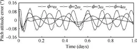
Fig. 9 Pitch attitude error with different uniform speed of the PV array in one day.
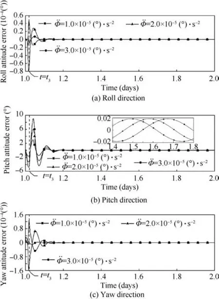
Fig. 10 Attitude error with attitude control system after one day.
6. Conclusions
In order to study the relative motion among the three subsystems, the multi-rigid body coordination equation is constructed through kinematic and dynamic analysis. To study the influence of the operating conditions of the PV array on the overall system’s attitude,two types of kinematic conditions are set in this study: uniform rotation and uniform acceleration rotation. In the coordination equation, because the term containing the angular acceleration of the PV array exists only in the pitch direction, the uniform acceleration rotation only affects the attitude deviation in the pitch direction.
An attitude control system is designed. The acceleration process of the PV array is applied to the attitude control system as an interference, and the ability of the attitude control system to stabilize the deflected attitude is studied. Through simulation,we found that when the PV array rotates at a constant angular velocity,the attitude deviation angle in the pitch direction varies periodically after the initial deviation attitude is stabilized, and that this effect is mainly caused by the influence of gravity gradient torque.
In the future, the attitude control method should be approved for the SSPS system with the PV array under complex situation. And the distributed and centralized control for the attitude control system should be studied to improve the dynamic response of the system with the disturbance factors.
Declaration of Competing Interest
The authors declare that they have no known competing financial interests or personal relationships that could have appeared to influence the work reported in this paper.
Acknowledgements
This study was co-supported by the National Natural Science Foundation of China (Nos. 51775404, U1637207, 51607131),the Qian Xuesen Laboratory of Space Technology Seed Fund(No. QXSZZJJ03-08), the Natural Science Foundation of Shaanxi Provincial Department of Education, China (No.19JK0848), and the Natural Science Foundation of Shaanxi Province, China (No. 2020JQ-595).
 CHINESE JOURNAL OF AERONAUTICS2021年5期
- CHINESE JOURNAL OF AERONAUTICS的其它文章
- Ferrofluid moving thin films for active flow control
- Preliminary study on heat flux measurement data of TT-0 flight test
- An analysis and enhanced proposal of atmospheric boundary layer wind modelling techniques for automation of air traffic management
- Jet sweeping angle control by fluidic oscillators with master-slave designs
- Hot deformation behavior and microstructure evolution of the laser solid formed TC4 titanium alloy
- Electrochemical trepanning with an auxiliary electrode
