Energy-saving and accurate motion control of a hydraulic actuator with uncertain negative loads
Bobo HELIAN, Zheng CHEN,b,*, Bin YAO
a State Key Laboratory of Fluid Power and Mechatronic Systems, Zhejiang University, Hangzhou 310027, China
b Ocean College, Zhejiang University, Zhoushan 316021, China
c School of Mechanical Engineering, Purdue University, West Lafayette, IN 47907, USA
KEYWORDS Adaptive robust control;Hydraulic actuator;Meter-out throttling;Motion control;Servomotor pump
Abstract Pump controlled hydraulic actuators are wildly used in the aerospace industry owing to the advantages of energy-saving and integrated configurations. Negative loads may occur to actuators due to external force loads or the inertial force when the actuator decelerates significantly.Uncertain negative load working conditions may cause cavitation, actuator vibration, and even instability to the motion control if the actuator is without sufficient meter-out damping. Various types of hydraulic configuration schemes have been proposed to deal with negative loads of hydraulic actuators. However, few of them can simultaneously achieve energy saving and high control accuracy. This study proposes an energy-saving and accurate motion tracking strategy for a hydraulic actuator with uncertain negative loads. The actuator’s motion is driven by a servomotor pump,which gives full play to the advantage of energy-saving.The meter-out pressure is controlled by proportional valves to provide the optimized meter-out damping.The nonlinear adaptive robust control law is designed, which guarantees the control stability and achieve high tracking accuracy.An integrated direct/indirect adaptation law obtains satisfactory parameter estimations and model compensation for asymptotic motion tracking. Comparative experiments under different working conditions were performed to validate the advantages of the proposed control strategy.
1. Introduction
Pump controlled hydraulic actuators have the advantages of energy saving, integrated configurations, and high power-tovolume ratio.1Therefore, they are wildly applied in the aerospace industry2and many other fields.Thanks to the advanced servo technology, the servomotor pump drive actuators have fast responses and can achieve high motion control accuracy as well as excellent energy efficiency.3
Negative loads may occur to actuators due to the inertia of the mass load when the actuator decelerates quickly. Another case of negative load is that an external force load acts on the actuator and is in the same direction as the motion tracking reference. When hydraulic actuators working under negative loads,the cylinder actuator is unable to keep accurately tracking the desired trajectory if the return side of the actuator is without sufficient meter-out damping.Meanwhile,the pressure of the pump-connected chamber could reduce greatly and drop to a very low value, which could cause cavitation, actuator vibration, and other nonlinear phenomenons.4These could bring about instability to the actuator’s motion control. In addition, the cavitation in the cylinder chamber can damage the hydraulic components.5Modified hydraulic configurations are required to avoid these phenomenons and to keep the motion tracking accuracy under negative loads.
To deal with negative loads of hydraulic actuators,various types of hydraulic configuration schemes have been proposed.Counterbalance valves (CBV) are widely used in open-circuit hydraulic systems, which can adjust the pressure and flow of the actuator under negative loads. However, dynamic responses of the CBVs are usually unsatisfactory, which may cause flow vibration,6and cannot be used for accurate motion control.Electro-hydrostatic actuator(EHA) is a typical pump drive actuator system. To avoid cavitation and suction under negative loads, an accumulator is applied in typical EHAs,7which maintains the pressure and compensates the fluid loss.This design requires more hardware auxiliaries,8,9meanwhile,the equipment is sensitive to load fluctuation due to the lack of meter-out damping.
Independent metering systems(IMS)decouple the pressure control of each chamber,10which provide control flexibilities to deal with negative loads. In literature,11a decoupling control method was proposed for an electro-hydraulic system with multiple actuators to address low damping issues under different working conditions. In literature,12a three-level controller of an independent metering system is proposed, which achieved energy-saving and precise control. An energy-saving approach is proposed for a pump and valve combination control system with multiple actuators.13In literature,14a robust controller is proposed for an integrated direct drive volume control steering system to achieve accurate position tracking.In literature,15,16the independent metering valves control method is combined with the direct pump control method,achieving high energy efficiency and high motion control accuracy. Although the above IMSs can achieve better energy efficiency in comparison to conventional valve control systems,throttling energy loss is inevitable to all these valvecontrolled independent metering systems, which essentially limits the energy efficiency. In literature,17a pump and valve combination strategy is proposed to especially handle negative loads,in which a pump maintains the pressure in one chamber while a valve controls the meter-out flow of the other chamber to realize the speed tracking of the actuator.This design has an energy-saving advantage owing to its pump and valve separately drive configuration, and it can obtain satisfactory control performance in simple motion tracking. However,this strategy cannot handle complex forth-and-back tracking tasks.
The unknown external force load can be regarded as a disturbance to the actuator, which affects the tracking accuracy and system control stability. Therefore, the anti-disturbance ability of the control algorithm is another key to improve tracking performance of hydraulic actuators with uncertain negative loads. State-of-arts of nonlinear control algorithms have been proposed to handle the unknown disturbance and to ensure robustness. In literature,18an active disturbance rejection adaptive control scheme is proposed for motion control of a hydraulic servo system. A disturbance observer is designed in literature,19to reject disturbances for a hydrostatical drive heavy vehicle. Literature20used a robust integral of the sign of the error (RISE) nonlinear feedback to attenuate unmodeled disturbance in motion control of a hydraulic system. Extended-state-observer-based control methods are proposed for hydraulic systems in literature,21,22which achieved high tracking performance with disturbance adaptation. A nonlinear position tracking controller with a disturbance observer(DOB)is proposed in literature23to track the desired position in the presence of disturbances of electro-hydraulic actuators. The adaptive robust control (ARC) algorithm was used in precision motion control of hydraulic systems,24,25and other nonlinear systems,26,27which show excellent capability in handling uncertain disturbances and model nonlinearities. Furthermore, the integrated direct/indirect adaptive robust control (DIARC) can achieve both high control accuracy and satisfactory parameter estimation. Therefore,DIARC has great potential on accurate motion control of hydraulic actuators with uncertain disturbances.
This study proposes an accurate motion tracking controller for a hydraulic actuator with uncertain negative loads. The actuator’s motion is driven by a servomotor pump,which gives full play to the advantage of energy-saving. The meter-out pressure is controlled by proportional valves. Contributions of this study can be sorted as:
(1) A meter-out pressure regulation method is proposed,which consists of an optimized meter-out pressure planner and a pressure tracking controller. The meter-out pressure regulation provides the required damping to avoid cavitation and suction under negative loads meanwhile maintaining optimized energy efficiency;
(2) A DIARC strategy is designed for both the actuator motion tracking and the meter-out pressure tracking.The proposed control strategy can estimate the uncertain loads and achieve high control accuracy in the presence of uncertain disturbances and other inherent nonlinearities of the hydraulic actuators.
Modeling of the hydraulic actuator system and controller design with theoretical proof are detailed in this paper. To demonstrate the control accuracy and versatility of the proposed control strategy, comparative experiments are performed with different working conditions, including an inertia mass load with a fast back-and-forth tracking trajectory, and an external negative force load.
2. System modeling
The hydraulic schematic of the proposed hydraulic system is shown in part (a) of Fig. 1. Four valves are utilized, including two reversing valves and two proportional valves. The actuator is driven by a servomotor pump while the reversing valves(V3 and V4) decide the direction of actuator motion. The two proportional valves (V1 and V2) control the meter-out pressure to provide throttling damping.
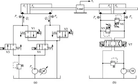
Fig. 1 Schematic of proposed hydraulic system.
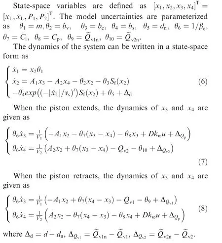
The actuator dynamics is modeled as

where kqis a lumped coefficient for valve flow rate, ΔPvirepresents the pressure difference. Δviis a lumped uncertain nonlinear term.31Besides,uvirepresents the valve voltage input for spool position.32
3. Meter-out pressure planning and control
When hydraulic actuators working under negative loads, the cylinder actuator is unable to keep accurately tracking the desired trajectory if the return side of the cylinder is without meter-out damping.The pressure of the pump-driven chamber can drop to a very low value, which could cause cavitation,actuator vibration, and other nonlinear phenomenons.
In this section, a meter-out pressure regulation method is designed to accurately track the given trajectory under negative loads condition. A meter-out pressure planner is designed to obtain an optimized meter-out pressure,which can generate the appropriate damping. Besides, a DIARC controller for meter-out is designed to track the desired meter-out pressure.
3.1. Meter-out pressure planning
A meter-out pressure planner is designed to obtain an optimized meter-out pressure, which can generate the appropriate meter-out damping for motion tracking. Meanwhile, it can maintain the pressure of the pump-driven chamber to avoid cavitation and suction under negative loads. The working mode selection of the pump and valve combined configuration is given by Table 1,in which ∈is a preset error threshold.Three working modes are defined with the considerations of the velocity of desired trajectory, position tracking error, and the configuration of the valves. In mode 1, the hydraulic force drives the actuator to extend, and the pump drives the chamber 1 (left) of the actuator while the meter-out pressure P2is controlled by V2. In mode 2, the hydraulic force drives the actuator to retract, the pump drives the chamber 2 (right)while the meter-out pressure P1is controlled by V1. In mode 3, the pump stops.
When the cylinder extends, P2is the meter-out pressure. A desired pump-driven chamber pressure Pε1is designed for P1when the hydraulic actuator moves under negative loads.
Based on piston load force FLd=P1A1-P2A2, P1can be described as
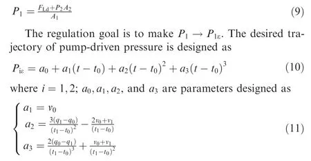
Assignments of q0, q1, v0, and v1are given by Table 2.
In Table 2, q0=Pi0is a preset value. ˙Piis the gradient of the pressure, which can be obtained by observers as follows,
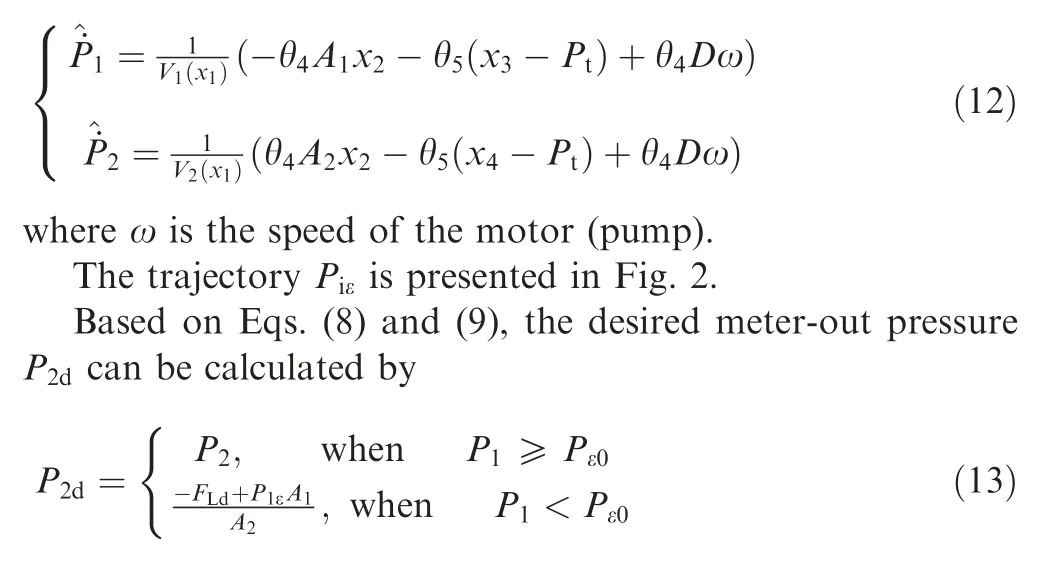
3.2. Pressure tracking controller
An adaptive robust pressure control method is proposed in this section to track the desired meter-out pressure. As P2is defined as the meter-out chamber pressure when the cylinder extends, and the pressure dynamics can be described as
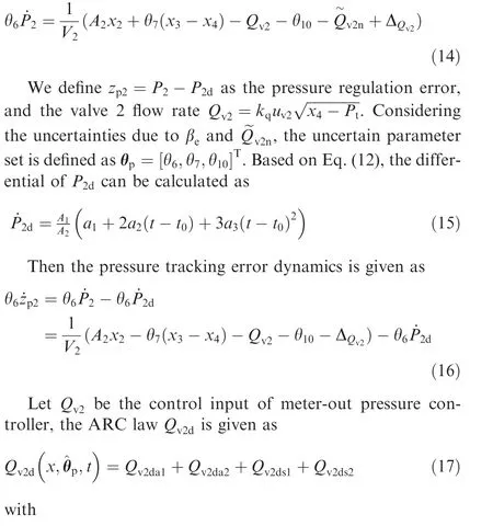

Table 1 Working modes.

Table 2 Trajectory constraints.

Fig. 2 Desired pressure trajectory.
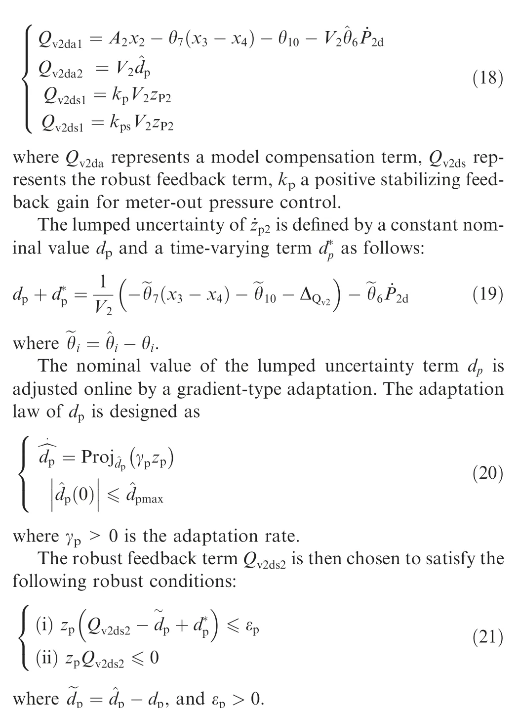
Similarly, when the cylinder retracts, the pressure tracking error is defined as eP1=P1-P1d.In this condition,the desired flow rate Qv1d(for valve 1) is designed to track the desired meter-out pressure P1dand can be obtained by the above steps.
The valve i(i=1, 2)voltage input uvican be reversely calculated by Eq. (5), and be given as

4. Pump direct drive controller design
The structure of the entire control strategy is presented by Fig. 3. The control strategy mainly consists of two parts. Part 1 is a two-step pump drive controller; Part 2 is a meter-out pressure tracking controller, which has been detailed in Section 3.The control objective is to make the actuator’s position accurately track a given trajectory in the presence of negative loads.
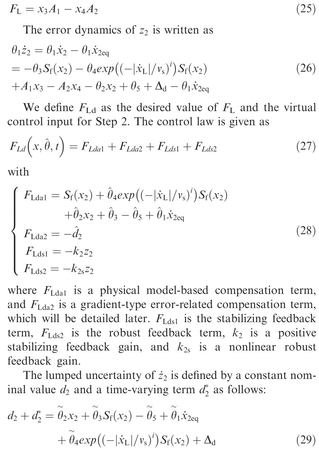
In this section, an adaptive robust backstepping controller is designed for the servomotor pump. Considering the uncertain nonlinearities and parametric uncertainties of the proposed hydraulic system, the backstepping controller consists of two steps. Step 1 is designed for the position tracking step,and step 2 is designed for the piston force tracking.
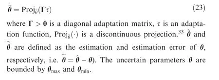
The adaptation law is given by
4.1. Motion tracking
The position tracking error is defined as z1=x1-xd(t ). z2is defined as

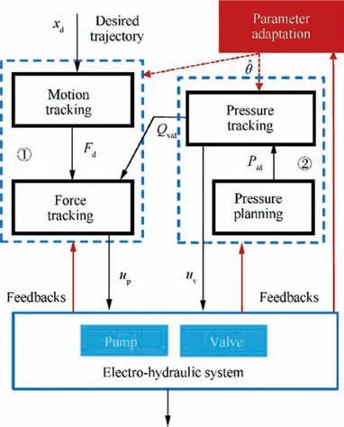
Fig. 3 Controller structure.
where x1d(t ) is the given reference trajectory, andk1is a positive feedback gain.
FLis defined as the hydraulic force on the piston which is modeled as

4.2. Force tracking
The input error of Motion tracking step is defined as z3=FL-FLd. The motor-pump voltage input u is defined as the control input to minimize z3.
The error dynamics when the cylinder piston extends can be described as
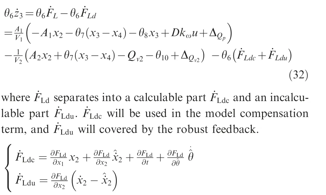
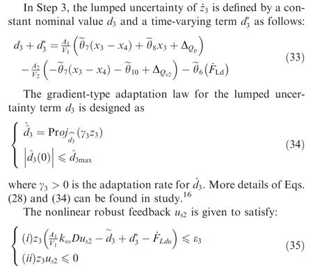
Considering the nonlinearities and uncertainties of Eq.(32),the control input is designed as

The nominal value of the lumped uncertainty term d2is adjusted online by a gradient-type adaptation.The adaptation law of d2is designed as
where ua1is the model-based compensation,and ua2is an errorrelated compensation term. us1is the stabilizing feedback with k3>0, and us2is a robust feedback term with feedback gain k3s.
5. Parameter estimation
An integrated direct/indirect adaptation law is designed in this section to estimate the external negative load and other uncertain parameters.
The adaptation law is given as
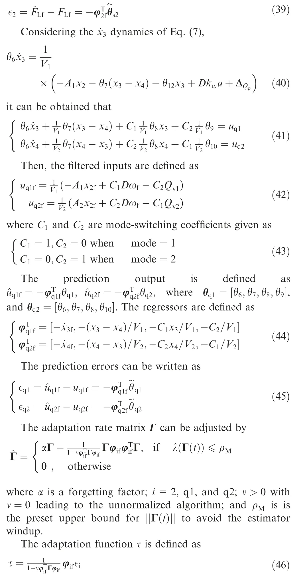
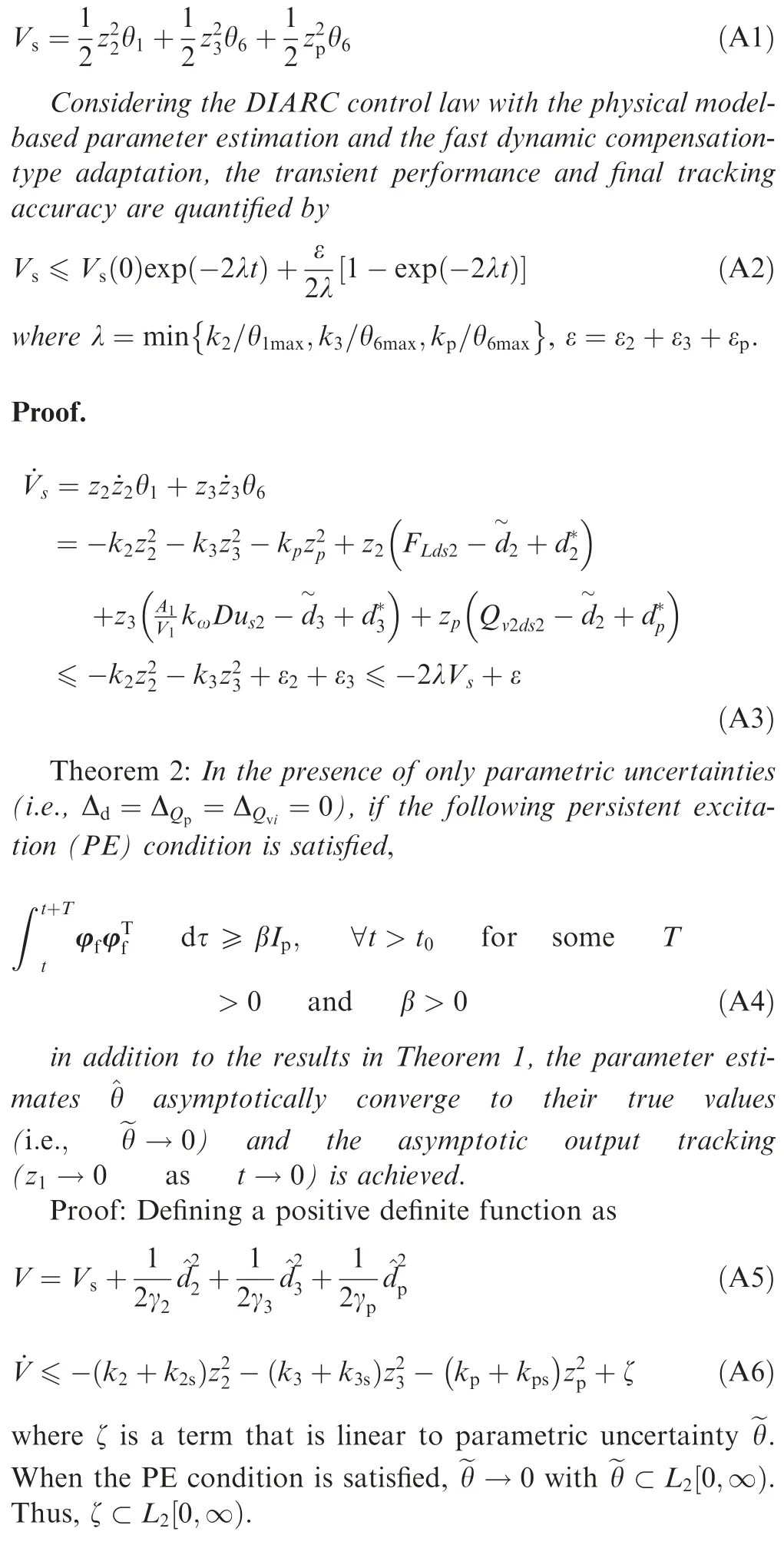
The stability of the system and asymptotic motion tracking performance when parametric uncertainties exist only can be rigorously proved. The theoretical proof is detailed in the Appendix A.
6. Experiments
To validate the presented control strategy,comparative experiments are performed in this section.
6.1. Experiment Set-up
The experimental setup is shown in Fig.4,in which Fig.4.(1)shows the cylinder actuator with inertia mass load and force load given by load cylinder; Fig. 4. (2) shows the valve block of the load system;Fig.4.(3)shows the valve block of the control system; Fig. 4. (4) shows the servomotor pump station.The hydraulic schematic of the setup has been shown in Fig.2.

Fig. 4 Setup of hydraulic actuator.
The pump used in the control system is a Bosch Rexroth PGF3 internal gear pump with 25.4×10⁻⁶m3/r displacement.The servomotor is a Inovance ISMG1 permanent magnet synchronous AC servomotor, which are shown in Fig.4. (4). The two reversing valves(Valve 3 and Valve 4)are HydraForce SV.The proportional valves (Valve 1 and Valve 2) are 4WREE of Bosch Rexroth.The mass of the inertia load was 250 kg.The control cylinder’s piston diameter is 50 mm, and the rod diameter is 36 mm. The controller is operated by a National Instruments (NI) PXI system with sampling time tsof 0.005 s.
The time-domain identifications were operated to identify the response speeds of the servomotor-pump dynamics and the solenoid reversing valves (Valve 1 and Valve 2) dynamics.The servomotor works under a speed mode with the servo driver, in which the voltage input u is proportional to the motor(pump) speed ω. A approximate transfer function G(s )=ω(s )/u(s ) of the servo motor dynamics was conducted by a first-order dynamic model.The time constant of the identified dynamic model is 0.006, which shows that the response speed is very fast. Besides, the solenoid reversing valves can be quickly activated and opened, which is fast enough for the hydraulic system where the valves do not switch frequently.Therefore, both servomotor electrical dynamics and reversing valve dynamics are neglected as high-frequency dynamics.
In addition, a flow rate mapping was carried out to model the flow characteristics of proportional valves (Valve 1 and Valve 2). The mapping results present the relationship of flow rate, pressure difference at valve port and voltage input.According to the mapping results, the valve flow coefficient of Eq. (5) is given by kq=9.113. The dead zone of the slide valve is 1.15 V, and the actual valve voltage input is further given as

where udv=1.15.
The schematic of the load system is shown by part (b) of Fig. 2. A double-rod cylinder was used in the load system, in which one side of the rod was fixed with the mass to generate the force load.The motion of the load cylinder is control by a proportional valve.The pressures of each cylinder chamber are controlled by two proportional relief valves. The diameter of the load cylinder is the same as that of the control cylinder.
6.2. Comparative experiments
Negative loads working conditions could occur due to the inertia of mass load when the actuator quickly brakes,or a(negative) force load which is in the same direction of the moving reference.Therefore,two cases were conducted to demonstrate the versatility of the proposed control strategy in different working conditions.
Case 1:The hydraulic schematic of Case 1 is shown by part(a) Fig. 1. The cylinder actuator is fixed with a 250 kg inertia load. The desired tracking trajectory is a fast back-and-forth trajectory which is shown in Fig. 5. The max acceleration/deceleration is ±2 m/s2(Fig. 5).
Case 2: A negative force load is added to the actuator by the load hydraulic system shown by the part (b) of Fig. 1.The load piston pulls the mass to generate a negative force load when the control actuator extends.
To show the advantages of the proposed controller, three comparative control strategies were chosen as
C.1 The proposed control strategy which is consisted of the DIARC backstepping pump controller and the meterout pressure controller.
C.2 DIARC backstepping pump controller only (without meter-out throttling).
C.3 High-gain gradient type disturbance observer (DOB)-based controller for the same system of C1.
6.2.1. Results of Case 1
The motion tracking performance of C1 and C2 are compared in Case 1 to demonstrate the effectiveness of the meter-out throttling.C1 is the proposed control strategy for the servomotor pump and proportional valves combined control actuator shown in part (a) of Fig. 1. For comparison, C2 used the DIARC backstepping pump controller of C1 for a pumpdriven actuator, in which the two proportional valves were replaced by reversing valves.
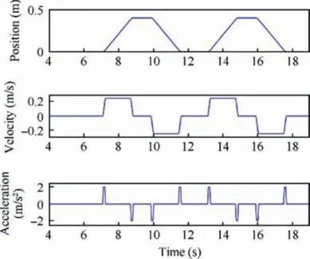
Fig. 5 Desired point-to-point trajectory in Case 1.
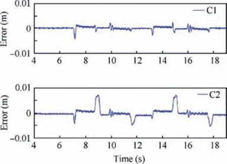
Fig. 6 Tracking errors in Case 1.

Fig. 7 Pump flow rates in Case 1.
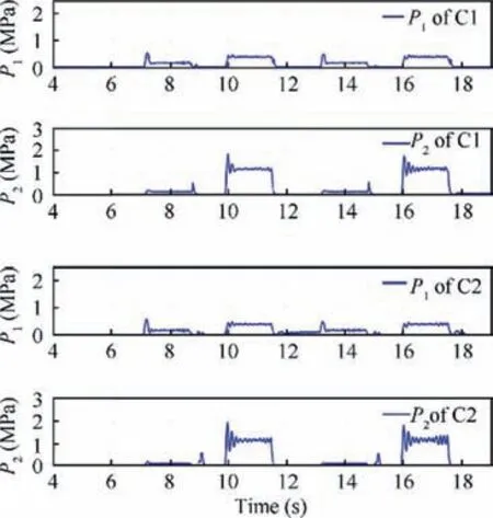
Fig. 8 Pressures in Case 1.
Comparative motion tracking results are presented in Fig. 6. As the results of C2 shows, large tracking error occur when the actuator was decelerating (i.e., t=8.7 s, and t=11.6 s). This is because the meter-out chamber could not provide sufficient damping to decelerate the cylinder. Under this negative load condition, it is incapable for the system of C2(pump drive actuator without meter-out throttling)to track the desired trajectory accurately. In contrast to C2, C1 achieved high motion tracking accuracy in the transients of accelerating and decelerating.The results indicate that the proposed meter-out pressure regulation method is effective.
Pump flow rates of both controllers are shown in Fig. 7.The pressures are presented in Fig.8.The energy consumption can be calculated by

By Eq.(48),the energy consumption of the actuator moves back and forth once (i.e., 7-12 s) can be obtained, which are 681 J (by C1) and 687 J (by C2), respectively. It indicates that the meter-out throttling under negative loads does not consume extra energy. The proposed strategy can simultaneously achieve high energy efficiency and high motion tracking accuracy under negative loads.
6.2.2. Results of Case 2
The motion tracking performance of C1 and C3 are compared in Case 2 to demonstrate the robustness and tracking accuracy in the presence of unknown negative disturbance.C3 applied a well-used gradient type disturbance observer (DOB)-based controller for the actuator motion tracking of the same system of C1, in which the gain of the observer is tuned to make the tracking performance as accurate as possible.
As tracking results of Case 2 shown in Fig. 9, C1 achieved high tracking performance in both high transients and steadystates.The steady state tracking error of C1 minimized to zero in the presence of the large uncertain negative force load. As the tracking error of C2 shows, the steady-state error approached zero with the help of the disturbance observer,but large error arose in transients. Although C2 realized fast dynamic response speed,as well as C1,did,the transient tacking error of C2 was relatively large (when t=7 s and t=16.5 s) due to the inaccurate model compensation.
The disturbance on-line estimation results are presented in Fig.10 as well as the measured load force.The load force was approximatively obtained by FL=PaAa-PbAb. It is clearly shown that C1 achieved better disturbance estimation performance in comparison with C3 owing to the integrated direct/indirect adaptation.
The uncertain disturbance estimation results are shown in Fig. 10. It is clear to see that C1 achieved better estimation results compared to C3.The results demonstrate that the integrated direct/indirect adaptive robust control can obtain satisfactory parameter estimation by the proposed adaption law Eq. (36), while achieving high tracking accuracy in transients as well as steady-states.
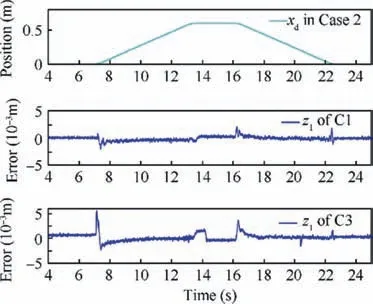
Fig. 9 Reference and tracking errors in Case 2.
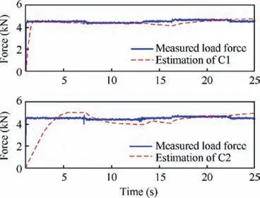
Fig. 10 Force load and estimations.
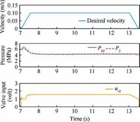
Fig. 11 Pressures and valve input in Case 2.
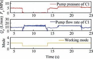
Fig. 12 Pump pressure, flow rate, and mode in Case 2.
When the velocity of the actuator is positive, the direction of the motion and the direction of the force load are the same,so the actuator was moving under a negative load.During this time, the meter-out pressure P2is controlled by valve 2 to make P2tracking the desired metering pressure P2d. The pressure tracking results and valve control input are shown in Fig. 11, which shows accurate pressure tracking performance.
The pump pressure,flow rate,and working mode in Case 2 are shown in Fig. 12. It shows that the pump pressure Ppwas regulated at a very small value under the negative load working condition (i.e., t=7-14 s). Meanwhile, the pump generated effective flow rate Qpto drive the actuator while avoiding the suction. Considering the very low pump pressure during motion tracking,energy-saving was realized by the proposed control method.
7. Conclusion
This study proposes an accurate motion tracking strategy for a hydraulic actuator with uncertain negative loads. The actuator’s motion is driven by a servomotor pump, which realizes high energy efficiency and motion tracking accuracy. The meter-out pressure is controlled by proportional valves to provide the optimized meter-out throttling for motion tracking under negative loads. The adaptive robust control law is designed to guarantee stability. The negative load and other uncertain parameters are estimated by an integrated direct/indirect adaptation law,achieving satisfactory model compensation for asymptotic motion tracking. Comparative experiments were carried out under different working to validate the excellent control performance and versatility of the proposed control strategy.
Declaration of Competing Interest
The authors declare that they have no known competing financial interests or personal relationships that could have appeared to influence the work reported in this paper.
Acknowledgements
This work is supported by the National Natural Science Foundation of China (No. 52075476 and No. 61633019), ScienceFund for Creative Research Groups of National Natural Science Foundation of China (No. 51821093).

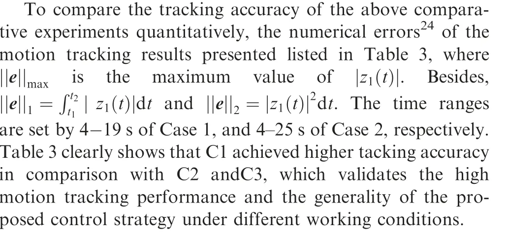
Table 3 Numerical comparison of tracking errors.
Appendix A. The theoretical proof detailed in this section,which guarantees the stability of the entire hydraulic system and the asymptotic motion tracking performance.
Theorem 1: A positive definite function36is defined as
 CHINESE JOURNAL OF AERONAUTICS2021年5期
- CHINESE JOURNAL OF AERONAUTICS的其它文章
- Ferrofluid moving thin films for active flow control
- Preliminary study on heat flux measurement data of TT-0 flight test
- An analysis and enhanced proposal of atmospheric boundary layer wind modelling techniques for automation of air traffic management
- Jet sweeping angle control by fluidic oscillators with master-slave designs
- Hot deformation behavior and microstructure evolution of the laser solid formed TC4 titanium alloy
- Electrochemical trepanning with an auxiliary electrode
