A novel architecture of electro-hydrostatic actuator with digital distribution
Jing YAO,Pei WANG,Zhosheng DONG,Dongting JIANG,Tong SHA
a School of Mechanical Engineering, Yanshan University, Qinhuangdao 066004, China
b Key Laboratory of Advanced Forging & Stamping Technology and Science of Ministry of Education of China, Yanshan University, Qinhuangdao 066004, China
c Hebei Key Laboratory of Heavy Machinery Fluid Power Transmission and Control, Yanshan University, Qinhuangdao 066004,China
KEYWORDS Asymmetrical flow;Digital distribution;EHA;High-speed on-off valve;Nonlinearity;PWM control
Abstract To address the flow imbalance rapidly of the asymmetric Electro-Hydrostatic Actuator(EHA), this paper presents a novel architecture of asymmetric EHA with the Digital Distribution(EHA-DD). It also improves the flow nonlinearity and control accuracy of the pump,especially in the low-speed condition. The digital distribution with two High-Speed on-off Valves (HSVs) not only balances flow instead of the check valves,but also replaces the pump at the low-speed to control output flow by adjusting the PWM signal.The pump and HSVs are the crucial components to control flow output. Firstly, the flow calculation models of the pump and the duty ratio inversed model of the HSV are obtained through experimental tests and the identification method. To get the control input signal for the required flow, the pump speed and PWM duty ratio for the HSVs are inversed to compensate for flow output. Further, a multimode digital flow distribution control method based on pump speed, mainly including the pump-controlled mode for large flow demand and valve-controlled mode for little flow demand, is proposed to control the accurate flow output actively.The step extension experiments based on the flow calculation models are conducted on the EHA-DD prototype under elastic, opposite varying load. The results demonstrate that the EHADD realizes little position error by accurate flow control, and it is also beneficial to improve the service life of the pump.
1. Introduction
An electro-hydrostatic actuator (EHA) is a type of power-bywire(PBW)actuator that is widely used in aerospace and large commercial aircraft. The EHA is a typically pump-controlled drive system, integrated by a motor, hydraulic pump, hydraulic valve,and hydraulic cylinder1,2.It has become a crucial part of flight control systems due to the advantage of increased efficiency,reduced leakages,and lower overall weight.The performance of EHA can directly affect the overall flight characteristics of aircraft3. There exists several configurations can realize the different control method for system flow, such as a variable rotation speed control, variable displacement control, and simultaneous variable rotation speed and displacement control et al4-6. The EHA with the variable rotation speed control mainly consists of a variable speed motor and a fixed displacement acted as the power unit for EHA, and it has found applications in the aircraft.In this study,this typical configuration is taken as a research object due to its simple structure and high efficiency7,8.Moreover,two types of actuators are being used in the EHA system:symmetric cylinder and asymmetric cylinder9.A symmetrical cylinder system has good characteristics, such as reliability and simple structure, and is generally used in electric aircraft and aerospace control actuation systems10-12.The rapid development of EHA in the aerospace control system has put forward an increasing demand upon power output13. Compared with the symmetrical cylinder system, an asymmetric cylinder system has been widely concerned for a large output force and high power-to-weight ratio,such as spoiler,nose wheel steering system,aircraft landing gear extension-retraction system, even construction machinery, robots, etc14-19. However, there are still some issues like the flow imbalance of asymmetric EHA and nonlinearity and poor control accuracy of the pump, especially in low-speed conditions20,21.
In terms of the problem of flow difference due to asymmetry structure,many researchers explore some solutions,such as the use of a secondary pump, 3-port (asymmetric pump),et al.21,22. Quan, et al designed a parallel three-assignmentwindow axial piston pump to match the flow variation, but its high cost and complex structure limit the application23,24.Besides, the usage of control valves with the accumulator is also the common method to compensate for the flow asymmetry. The mainly control valves refer to pilot operated check valves and shuttle valves. Rahmfeld25theoretically investigated a solution with two pilot operated check valves and implement it on EHA. Wang et al.26exploited the internal pilot operated closed center shuttle valve.Oh et al.27proposed an oil tank with a pilot operated check valve to eliminate flow asymmetry in an EHA system and verified its feasibility through simulation analysis. Busquets and Ivantysynova28,29studied a simple configuration of an EHA adopting an improved pilot controlled check valve to balance the asymmetrical flow.It shows good control accuracy and reversing stability but is subjected by the pilot ratio and the system parameters matching. Most of the common pilot operated check valves solutions suffer from increased response time caused by the built-up pressure process, which also performs unstably in the fast dynamic hydraulic systems30. Additionally, the servo valve has been introduced to balance flow and improve the control accuracy in31,32,but it brings many other problems like increased cost and weight, declined the power-to-density, and severe heat,et al.The HSVs as the core components of digital hydraulic technology have the advantages of simple structure,fast response time, low cost, and low sensitivity to fluid pollution and have found application widely33,34.
However,the flow output of HSVs is not only nonlinear but also discrete. The nonlinearity region, saturation region, and dead region have greatly added the difficulty to obtain the excellent flow characteristics. Most of the researches explored the duty ratio,modulation frequency,dynamic and static characteristics, and so on35,36. The PWM and PWM-PFM control methods could compensate for the flow of different regions and expand the range of the duty ratio for the linear flow control37.The pump as a critical component of the EHA has a significant impact on the characteristics, energy efficiency, and reliability of EHA38.Gnesi et al39formulated a novel pressure compensation system for gear pump used in EHA to minimize power losses. The variation in volume efficiency of the pump due to pressure drop, its speed of rotation and leakage have adverse effects both on the flow characteristics and powerdensity-ratio of the pump9,13.Besides,when the fixed displacement pump works at below set minimum speed, the output flow is difficult to maintain stability and has strong nonlinearity30,40.And it also causes the issues of the low volumetric efficiency, heat, internal wear, etc. The HSVs with PWM control can replace the pump in low-speed operation to realize accuracy control by bypass throttling.Therefore,the HSV presents a new solution to the architecture of the asymmetric EHA for solving the asymmetry and nonlinearity of the output flow.
Aiming at the situation described above, this paper proposed a novel and simple architecture of the asymmetric EHA with digital distribution(EHA-DD)to address the issues of flow asymmetric and nonlinearity. Digital distribution with two HSVs replaces the common pilot operated check valves to quickly balance the flow asymmetry of the cylinder, and control accurate flow output by adjusting the PWM signal, especially in the pump low-speed nonlinear zone. Firstly, the flow characteristics of the pump and HSV were tested, then accurate calculation models of flow and duty ratio were established. On this basis, the flow calculation equations were inversed to get the control input signal, the pump speed and duty ratio for the HSV,to control and compensate for the output flow of the pump and HSV to weaken the adverse nonlinear effect, respectively. Subsequently, a multimode flow distribution control method is further proposed for the accurate flow output according to the pump operating speed.One is the pump-controlled mode, which is responsible for large flow control by the only pump and flow distribution by HSVs with on/off control during the high-speed operation.The other is the valve-controlled mode, which is responsible for little flow control closed to the target value by PWM control of one HSV and flow distribution by the other HSV during low-speed operation. Besides, the proposed EHA-DD and methods prevent the pump from severe heat and internal wear due to the pump works below the minimum speed.It not only provides a novel EHA architecture for flow asymmetric and nonlinearity,but also contributes to ensuring the pump works well and improves the service life of the pump.
2. Working principle of EHA-DD
The composition of the EHA-DD is shown in Fig.1.The system mainly consists of a power unit,actuator unit,distribution unit, safety protection unit, and electronic control unit. One servo motor and a fixed displacement pump work as a power unit to supply the power for the motion of the actuator unit(an asymmetric cylinder). The distribution unit composes of two HSVs and is responsible for balancing the asymmetric flow caused by the difference of effective piston area in the oil circuit with the cooperation of the oil supplement unit(an accumulator). The relief valves are used for setting the maximum system pressure,which is the safety protection unit.The electronic control unit is responsible for signal control and acquisition. The m is the mass of load, and the load suffers load force FL.

Fig. 1 Components of EHA-DD.
The EHA-DD mainly includes the pump-controlled mode and valve-controlled mode under the opposite load conditions,as shown in Fig.2.Generally,the pump is set a minimum flow Qpminto avoid the severe inner wear affecting the service life of pumps. In the working process, it begins with the pumpcontrolled mode to control the cylinder motion by pump only.Once the pump output flow is lower than minimum flow Qpmin,the EHA-DD system will switch to the valve-controlled mode,and the pump works at near the minimum speed nmin. At this moment, the HSV controls the cylinder motion.
In Fig. 2, there is a high pressure (red) determined by the load force FLon the cylinder and low pressure (blue) determined by the pump inlet and the state of charge of the accumulator. The accumulator is responsible for supplying or storing oil for the system due to the flow difference of the cylinder chamber. The digital distribution of flow base on the two HSVs with different functions under different control modes.In the pump-controlled mode, while the cylinder rod extends(see Fig. 2(a)), the valve 3.1 closes, but the valve 3.2 opens to make accumulator supply flow to the system due to insufficient flow from the rod chamber. While the cylinder rod retracts, valve 3.1 opens to make the accumulator store excess flow from the rodless chamber, meanwhile the valve 3.2 closes(see Fig. 2(b)). In the valve-controlled mode, the HSVs with PWM are used for the control of cylinder motion (3.1 for extension or 3.2 for retraction).When the cylinder rod extends(see Fig. 2(c)), the HSV 3.1 control accurate flow and the motion of the cylinder by adjusting the duty ratio of the PWM signal,and valve 3.2 opens to balance the flow asymmetry of the cylinder. Meanwhile, the accumulator supplies flow for the system, and the pump speed maintains at around the minimum speed nmin. Similarly, when the cylinder retracts in the valve-controlled mode (see Fig. 2(d)), the HSV 3.1 opens,and valve 3.2 with the PWM signal controls the motion of the cylinder.
The novel architecture of EHA-DD is at the initial phase,thus this study investigates the extension working condition under the opposite load to validate this architecture and digital distribution method of EHA-DD.Current work focuses on the thrust operation condition that applications mainly need to overcome the opposite load in this study. The accuracy of the system is determined by the control characteristics of the pump and the HSV. It is necessary to establish accurate flow calculation models of the pump and the HSV to improve the control accuracy of the system flow. The mathematical theory models involve many disciplines, such as dynamics, kinematics, and electromagnetics, but traditional modeling methods always ignore some nonlinear and uncertain factors to obtain low accuracy models. In this study, test experiments combine with theoretical derivation to achieve accurate flow calculation models of the pump and the HSV by the identification technology. Based on these models, the flow control methods need to be proposed,which can compensate for the nonlinearity of the output flow of the system.
3. Flow modeling and compensation control of the pump
3.1. Flow calculation model
In actual situations, the pump needs certain internal/external leakage due to the lubrication of the vital friction pair. This causes a certain deviation between the theoretical calculation flow and the actual output flow. It is assumed that the pump operates in opposite load case all the time considering the volumetric efficiency, the output flow from the pump to the hydraulic system is given as
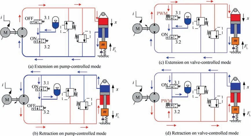
Fig. 2 Diagram of multimode digital distribution under different working conditions of EHA-DD.

where Qpis the pump flow, n is the speed of the servo motor,V0is the displacement of pump, and ηvis the volumetric efficiency of the pump,which depends on temperature,speed,differential pressure, etc.
It is generally believed that the volumetric efficiency of a hydraulic pump is affected by factors such as the pump port pressure P (assuming inlet pressure is around zero) and the input speed n of the pump. The relationship can be expressed as Qp=f(P, n). However, this relationship has a strong nonlinearity,so we conduct the test of the efficiency characteristics of the pump to fit the relationship. The schematic diagram of the test and the main parameters are shown in Fig. 3 and Table 1, respectively.
In the test, the speed of the electric motor begins with its minimum speed of 500 r/min and increases by 250 r/min every time,until it rises to 4000 r/min.Adjust the port of the throttle valve gradually until the pump outlet pressure reaches 15 MPa after stable speed operation of each time.The measuring cup is used to measure the volume of oil discharged from the hydraulic pump. At the same speed, we repeat the test five times and record the flow and pressure, then take an average of multiple measurements.Finally,we obtain the change of flow rate with pressure at different rotating speeds. The flow characteristic curve of the pump can be shown in Fig. 4.
The relationship Qp=f (P, n) is further described by the function fitting method. Considering the accuracy of fitting and the feasibility of solving the inverse function,the relationship is fitted as a binary quadratic function to fit Eq. (1), and the specific expression of Qp=f (P, n) is assumed as follows:

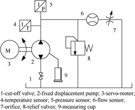
Fig. 3 Schematic diagram of pump test.
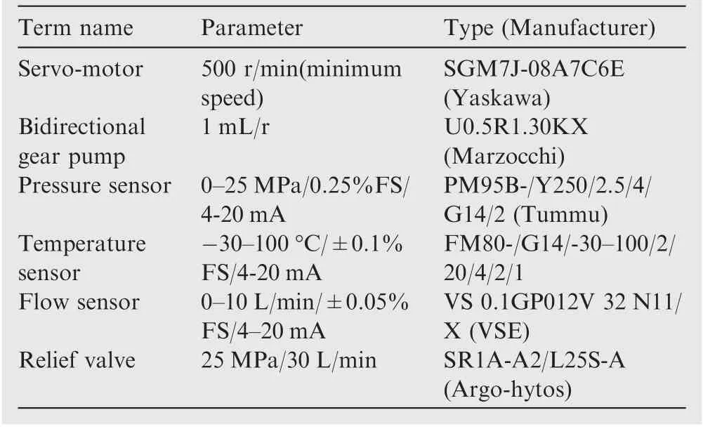
Table 1 Main parameters of pump test.
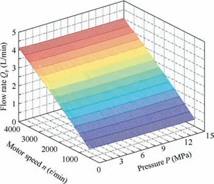
Fig. 4 Flow characteristic curve of pump.
We adopt Polynomial Curve Fitting method to indentify system by a fitting tool in MATLAB to fit the tested data,and the curve is shown in Fig. 4 is fitted into Eq. (2), and the coefficients of the expression of Qpare obtained as follows:

There are two indicators in the fitting tool to show the corresponding fitting precision.One is the R-square(coefficient of determination) measures how successful the mathematical expression Eq. (2) is in explaining the tested data in Fig. 4,which ranges is from 0 to 1,the higher the value,and the better the fit effect of Eq.(2).The other is RMSE(root mean squared error),a value closer to 0 indicates a better fit.R-square(coefficient of determination)=0.9998, and RMSE (root mean squared error)=0.01244. The high fitting accuracy reflects the fitted function reliability.
3.2. Flow compensation control method of the pump
In this subsection, according to the pump flow output Eq. (2)with the volumetric efficiency, we obtain the relationship of n=f(P, Qp), and further solve the input rotational speed n of the hydraulic pump based on this relationship. To achieve accurate flow output, the hydraulic pump performs flow compensation control according to the current two-chamber flow control demand and system pressure state of the hydraulic cylinder.
The pump speed is solved by the inverse function of Eq.(2),the concrete expression of n=f (P, Qp) can be written as follows.

The compensation control process of pump output flow in this paper is shown in Fig. 5.
The nccan be inversed by the input of the ideal output flow Qcand the pump outlet pressure P, then the control voltage calculation equation is

where Ucis the primary control voltage of the servo driver,Qcis the ideal output flow, and k1is the input gain of speed demand (r/min/V).
The flow feedforward compensation equation is

where Uqis the feedforward control voltage of the servo driver, and k2is the feedforward compensation coefficient(V·s2/L).
Therefore, the control voltage of the servo motor is

where U is the control voltage of the servo driver.
After the servo motor drives the hydraulic pump to rotate,the actual output flow of the hydraulic pump is Qp.The pump flow deviation as a measurement index is used to evaluate the compensation control effect, and the calculation equation is

where Qpe is the pump flow control deviation.
The flow compensation control method of the pump is validated by experiments with the schematic diagram, shown in Fig. 3. A sinusoidal flow demand with a frequency of 0.5 Hz,an amplitude of 0.5 L/min,and a median of 2 L/min is selected as the target flow. The experiments were finished by two control strategies for comparison, respectively. One is only the speed inverse compensation,and the other is the speed inverse compensation combined with flow feedforward compensation.The experimental results are shown in Fig. 6.
As shown in Fig. 6, under only the speed inverse compensation method(k1=500), the flow deviation fluctuates within 0.276 L/min according to Eq. (7), and there is flow hysteresis relative to the flow demand, see Fig. 6 (a). However, under the speed inverse compensation combined with the flow feedforward compensation method(k1=500,k2=0.18),the flow hysteresis is improved, and the flow deviation ranges within 0.115 L/min, see Fig. 6 (b). Therefore, the speed inverse compensation combined with flow feedforward compensation is an effective method to make the pump follow the flow rate instruction accurately and achieve the accurate output flow.
4. Duty ratio solution and flow control of HSV
4.1. Inversed model of duty ratio
The HSVs are the crucial component of flow digital distribution for the EHA. To realize the proportional control of the output flow of the valve,we select the pulse width modulation(PWM) signal as the driving signal of the HSV because of its simple control principle. By adjusting the duty ratio τ of the PWM signal, the opening and closing time of the HSV in a working cycle is controlled, and then the proportional control of the outflow can be achieved. The output flow characteristic curve41of the HSV under a certain differential pressure is shown in Fig. 7.

Fig. 5 Flow compensation control.
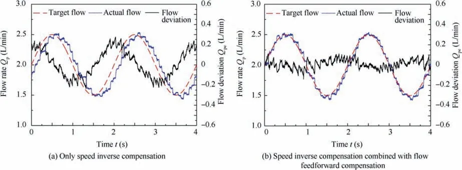
Fig. 6 Hydraulic pump output flow curves.
From Fig. 7, it can be seen that the output flow characteristic curve of the HSV consists of a dead region, a nonlinear region, a linear region, and a saturation region. To control the output flow accurately, the HSV should be operated in the linear region,in which the output flow can be expressed as

where qvis the output flow of the HSV, Kvis the liquid resistance coefficient, ΔP is the differential pressure, and m is the throttle shape factor.
To select a control frequency of the PWM signal,we tested the flow characteristics of the HSV at different frequencies.The schematic diagram of the test is shown in Fig. 8, and the main parameters of the HSV shown in Table 2.
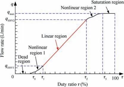
Fig. 7 Output flow characteristic curve of HSV.
In the test,the electric motor maintains 4000 r/min,and the output flow of the pump with 1 mL/r is 4 L/min. Keep a 0.5 MPa pressure difference before and after the HSV by the relief valve.Then,the PWM frequency of the high-speed valve is given from 10 Hz to 60 Hz with a 10 Hz interval, and the duty cycle signal varied from 0 to 1 with 0.01 interval.Finally,the pressure difference changed from 1 MPa to 15 MPa with 1 MPa interval. We record all the data of the output flow of the HSV. The experimental results are shown in Fig. 9.
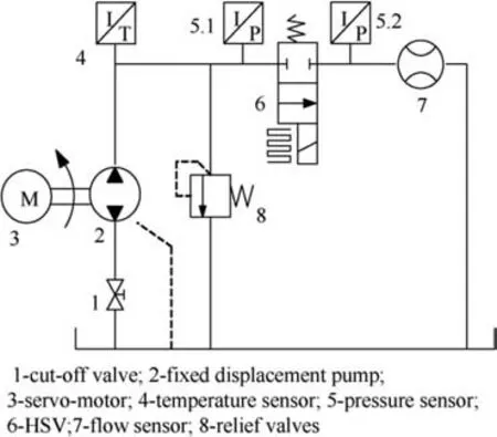
Fig. 8 Test schematic diagram of flow characteristic for HSV.
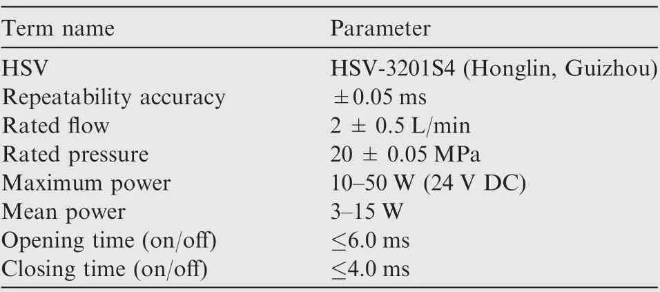
Table 2 Main parameters of HSV.
In Fig. 9, when the frequency ranges from 10 Hz to 30 Hz,the outflow is in the nonlinear region and has a large flow mutation in the transition from the dead region to the linear region. When the frequency ranges from 50 Hz to 60 Hz, the linear region is stepped,which means that the linearity is poor.The linear region of the output flow characteristic curve should be selected to improve the control accuracy of the output flow of HSVs. Therefore, the PWM frequency of the HSV is selected as 40 Hz, and the range of duty ratio is determined as τ ∈[0.3,0.8].
In Fig. 10, the linear region data, at 40 Hz frequency of PWM signal and duty ratio from 0.3 to 0.8, is processed to obtain the flow output characteristic curve of the HSV.
When the system is working, the output flow rate of the HSV is determined by the flow demand of the two chambers of the hydraulic cylinder and the output flow of the hydraulic pump.Since the output flow rate of the HSV is greatly affected by the pressure difference,it is necessary to obtain the relationship between the control signal duty ratio,the output flow rate,and the pressure difference, that is,

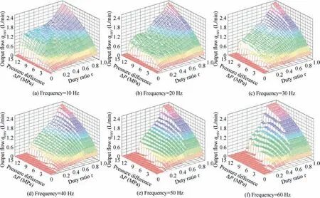
Fig. 9 HSV output flow characteristics at different frequencies.
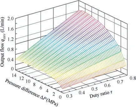
Fig. 10 Linear region flow output characteristic at 40 Hz.
The relationship of Eq. (9) is extracted from the data of Fig.10,interpolation processing is performed to obtain a duty ratio solution curve of the HSV control signal shown in Fig. 11.
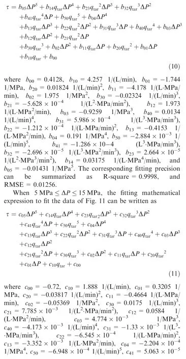
It can be seen from Fig.11,when 0.5 MPa ≤ΔP ≤5 MPa,minimum controllable flow at the valve port is 0.15 L/min.When 5 MPa ≤ΔP ≤15 MPa, the controllable flow varies from 0.47 L/min to 1.6 L/min, and the variation of the duty ratio is consistent with the flow rate at valve port under each pressure difference. To ensure the fitting accuracy, we use Polynomial Curve Fitting method to fit Eq. (10) by a fitting tool in MATLAB for different pressure difference ranges.When 0.5 MPa ≤ΔP ≤5 MPa, the fitting mathematical expression to fit the data of Fig. 11 can be expressed as
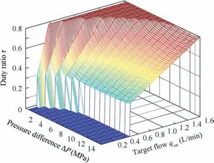
Fig. 11 Duty ratio solution curve of HSV control signal.

4.2. Flow control based on duty ratio solution method
The duty ratio solution method for flow control of the HSV in this paper is shown in Fig. 12. The controller consists of three modules: state judgment, duty ratio solving, and limitation.The state judgment module judges the working state of the system according to the pressure difference, and the solution module chooses the appropriate formula from Eqs. (11) and(12) according to the working state of the system and calculates the duty ratio τ. The signal limiting module is used to ensure that the duty ratio of the control signal is within a linear range.
The output flow deviation of the HSV as a measurement index is used to evaluate the flow control effect of the duty ratio solution method, and the calculation formula is given as follows:

where qveis the output flow deviation of the HSV.
The resolved duty ratio of flow control method has been verified by experiments with the schematic diagram, shown in Fig. 8. The duty ratio solution depends on the pressure difference and flow according to Eq. (9), as described in Section 4.1, with the pressure difference increases of valve ports,linear output flow becomes larger. In order to validate obviously and directly the flow control effect under the duty ratio solution method, thus the target flow commands with 0.2 HZ of the HSV are given as follows: (a) When the pressure difference is 2 MPa, the amplitude is 0.2 L/min, and the median value is 0.4 L/min. (b) When the pressure difference is 5, the amplitude is 0.4 L/min, and the median value is 0.6 L/min.
The experimental results are shown in Fig. 13. The actual output flow of the HSV follows the instruction flow well,and the flow deviation increase with increasing amplitude of the flow instruction signal and pressure difference. The flow deviation ranges from-0.064 L/min to 0.044 L/min according to Eq. (12), in Fig. 13(a). The flow deviation ranges from -0.147/min to 0.071 L/min in Fig. 13(b). The experimental curves prove the effectiveness of the resolved duty ratio for the flow control method.
5. Multimode digital flow distribution control method
Since the hydraulic pump has a minimum speed nminduring operation, the minimum speed of the pump corresponds to a minimum stable control flow rate Qpmin. When the required flow of the system is larger than Qpmin, the required flow of the system is provided by the servo motor pump unit. At this time,the HSV remains fully open or closed.When the required flow of the system is less than Qpmin,the hydraulic pump speed maintains at around the nmin, and the required flow is distributed by adjusting the duty ratio of the HSV. Therefore, it is necessary to control the digital distribution unit reasonably according to the different working conditions of the system.

Fig. 12 Duty ratio solution method process.
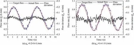
Fig. 13 HSV output flow sinusoidal response curve.
The minimum stable control velocity vminis defined as the velocity of the piston rod of the hydraulic cylinder when the output flow of the hydraulic pump is Qpmin, which meets the following requirement as

where ACis the acting area of the hydraulic cylinder (for retraction or extension).
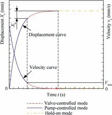
Fig. 14 Extension process of hydraulic cylinder.
Taking the extending process of the piston rod as an example, the working conditions of EHA-DD can be divided into three modes according to the velocity vcof the piston rod of the hydraulic cylinder, as shown in Fig. 14.
The condition for the pump-controlled mode is|vc|>vmin,and the condition for the valve-controlled mode is 0 <|vc|≤vmin. But it is worth noting that once EHA-DD enters the valve-controlled mode, this mode would control the piston rod approaches the target displacement until hold-on mode(vc=0). The rest of the process is in the pump-controlled mode. Besides, the displacement of the piston rod is defined as Xc, and the Xdcorresponds to the displacement deviation of piston rod motion at the moment entering valvecontrolled mode. The system state judgment, mode switching for the multimode flow distribution control process is shown in Fig. 15.
As shown in Fig. 15, in the pump-controlled mode, the speed inverse compensation combined with the flow feedforward compensation method is used for the motion control of the hydraulic system, aiming at the large deviation. While the valve-controlled mode is responsible for reaching its final target value by the duty ratio solution.In this mode,the digital flow distribution control method based on the velocity change with ramp signal is proposed to ensure the smoothness of the piston rod in the starting process and the control accuracy in the stopping process, as shown in Fig. 16. It utilizes the Xdto determine the ramp signal (red arrow line) as the target velocity vcr of the piston rod motion to approach the final displacement till hold-on mode by the cooperation of the power unit and the distribution unit.
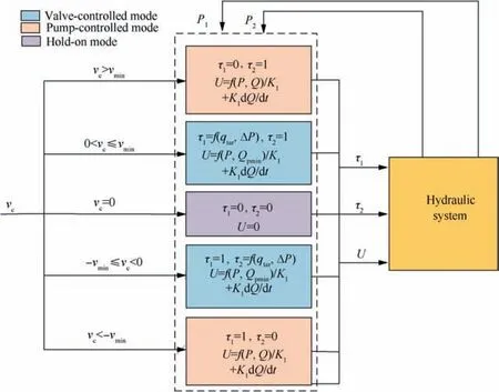
Fig. 15 Mode switching control module.

Fig.16 Flow distribution method based on velocity change with a ramp signal.
In Fig.16(a),during the starting process,the velocity of the piston rod increases from 0 to vmin along with the target velocity vcr. The time taken for this process is the deviation adjustment time te. The displacement deviation Xdof the piston rod of the hydraulic cylinder is the area surrounded by target velocity vcrand time te, and it is expressed as follows:

Therefore, the deviation adjustment time teis solved as follows:

Ignoring the influence of oil leakage due to the excellent sealing performance with little leakage of self-made hydraulic cylinder, thus the target velocity vcrof the piston rod is given in Eq. (16).

Thus, the target flow qtarof the HSV with PWM control during the starting process is solved as

Combined with the Eq.(10),the duty ratio of the HSV with PWM signal is rewritten as

Similarly, during the stopping process, the velocity of the piston rod decreases from vminto 0 along with the target velocity vcrin Fig.16(b),and the displacement deviation Xdcan be expressed as

The taken deviation adjustment time tethe for this process also satisfies Eq. (15). Ignore the influence of oil leakage, the target velocity vcrof the piston rod can be obtained.

Therefore,the duty ratio of the HSV with the PWM control during the stopping process must satisfy the Eq. (19).

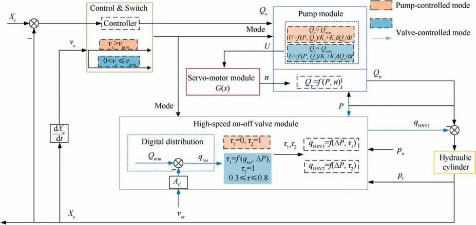
Fig. 17 Control diagram of EHA-DD.
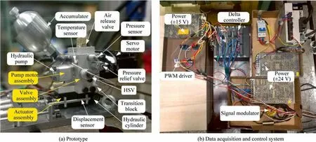
Fig. 18 EHA-DD architecture.
After the controller obtains the duty ratio,according to Eq.(18)or Eq.(21),the distribution unit is controlled to cooperate with the power unit, the piston rod velocity changes with the ramp target velocity to reach the final value in the starting or stopping movement process of the hydraulic cylinder. In conclusion, we give a top control view to express the control process clearly. When the target displacement Xris provided to control the extension of the piston rod of hydraulic, the Qcas the input of the pump module. Firstly, the pumpcontrolled mode is selected, so the pump module based on the speed inverse compensation combined with the flow feedforward compensation method calculates the control voltage U of the servo motor in pump-controlled mode. While, the HSV module deduces the duty ratio of the two HSVs of pump-controlled mode to control flow output, respectively.The first HSV is closed, but the second HSV is fully open for supplying oil for the EHA-DD system(see Fig.17).Aiming at the large deviation,the motion control of the hydraulic system is realized in this way. With approaching the target displacement Xr, the velocity vcdown to the vmin, and then the valve-controlled mode is selected for accurate control of little deviation. Meanwhile, the input Qcof the pump module is always the Qmin,and then the servo-motor maintains the minimum speed nmin to ensure the minimum flow output Qmin.On the other hand, the HSV module distributes flow qtarof the HSV based on the speed change with a ramp signal(target velocity vcr),and the duty ratio of HSV with the PWM signal is inversed to control flow output. The flow difference between pump output and HSV output is used for controlling the hydraulic cylinder motion and reach the final displacement.In the whole extension control progress, the pump-controlled mode switch to the valve-controlled mode based on rod velocity vc changing with the motor speed n, the state of first HSV switches from closing to duty ration control of PWM signal.But the second HSV is fully open all the time to supply oil to the system. The retraction control progress is similar to the extension.
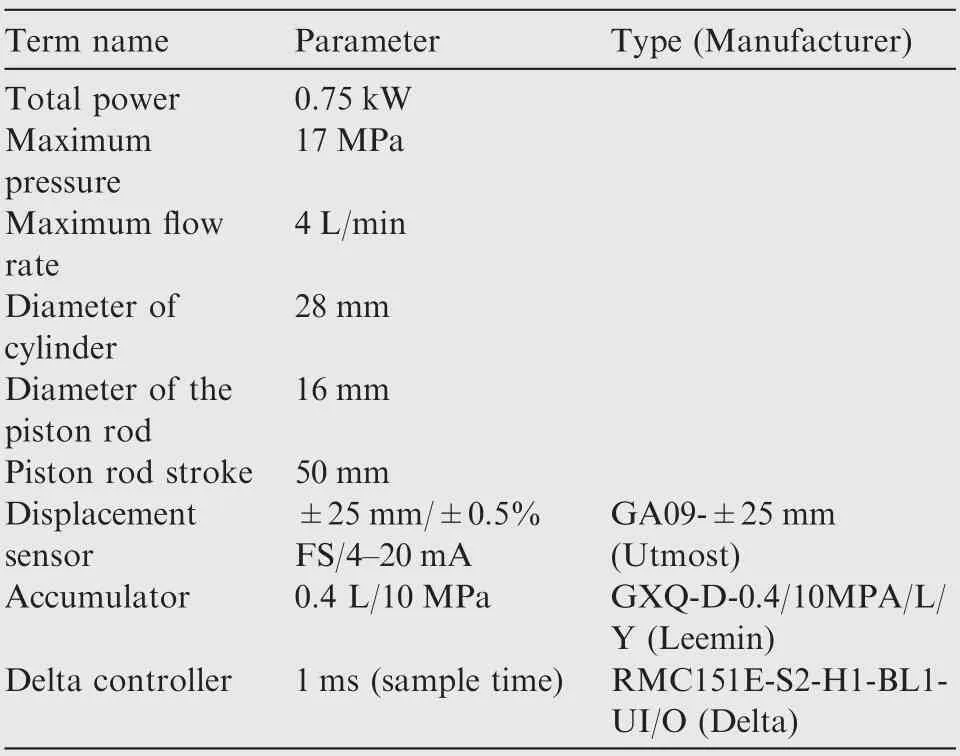
Table 3 Supplementary parameters of EHA-DD.
6. Experiments and discussion
6.1. Experimental prototype
The new prototype of EHA-DD has been built and tested in the laboratory to verify the EHA-DD performance and proposed multimode flow distribution control method.The prototype and the data acquisition and control system of EHA-DD are shown in Fig. 18, according to the system principle shown in Fig. 1.
There are three parallel springs, with 24.6 N/mm stiffness and limit stroke 70 mm,to simulate the load force and the preload is zero. Change the number of springs to adjust the load stiffness from 24.6 N/mm to 72.3 N/mm. Keep the oil temperature at 40±5 ℃during the experiments. The value of the pump minimum speed nmin is 500 r/min. The supplementary components and transducers are detailed in Table 3.The Delta controller is crucial to the data acquisition and control system,which is responsible for the D/A and A/D conversion to acquire data and control the hydraulic system (e.g. the speed of servo-motor). The control strategy is programmed on the Delta controller by Programming Tool,and the discrete signal output by I/O module. The PWM driven module utilizes MOSFET to amplify signal from the Delta controller to drive HSVs action with varying duty ratio of PWM signal. The signal modulator transfers the original transducer acquisition into the standard, recognizable signal of the controller.Besides, we adopt a low pass filter (0-100 Hz) of four-order Butterworth by RMCTools in motion controller to filter different collected signals. The key parameters are acquired in realtime, and output can be accomplished with 1 ms sample time by Plots Tool.
6.2. System step displacement experiment
This subsection takes the extension process of the hydraulic cylinder piston rod as an example to analyze step displacement experiments. The experiments started with the closing of the valve 3.1 and opening of valve 3.2, and then the pump drove the cylinder out. With the displacement deviation smaller,the required input speed of the pump would reach the minimum speed of 500 r/min. Next, the flow distribution control method based on the velocity change with a ramp signal is used for controlling the piston rod to reach the target displacement gradually by the coordination between valve 3.1 with PWM and opened valve 3.2 in the valve-controlled mode.
When the pump speed works at 500 r/min, the output flow is 0.5 L/min.According to the flow characteristics in section 4,the minimum steady flow in the linear region is 0.47 L/min under the pressure difference from 5 to 15 MPa,which is close to the output flow of the pump.Therefore,the rodless pressure needs below 5 MPa to realize the distribution flow.The multimode flow distribution control method was used in the step displacement setpoints of 0-5 mm and 0-20 mm, respectively.The experimental results are shown in Figs. 19 and 20.
It can be seen from Figs.19 and 20 that under the different step displacement inputs, the pump-controlled mode and valve-controlled mode appear in the extension process of the piston rod to the target displacement. According to the given displacement, the motor speed quickly exceeded 500 r/min before the starting process of position rod extension, and the system directly entered the pump-controlled mode. The velocity and displacement also increase rapidly, with motor speed increasing.The displacement of the piston rod tracked the target displacement, and the displacement deviation decreases gradually.In the pump-controlled mode,the piston rod velocity of the hydraulic cylinder is only affected by the output flow of the hydraulic pump.
When the motor speed and velocity slow down until the motor speed equals 500 /min. At this time, the valvecontrolled mode is selected, the motor speed change around 500 /min. The acquired displacement is used to calculate Xd,which is collected to design the target velocity vcrwith a ramp signal. According to the target velocity vcr, the flow distribution qtarof the HSV with PWM signal can be obtained used for the solution of duty ratio τ (0.3-0.8) based on Eqs. (20)and (21). The displacement gradually closes to the target displacement with the target velocity and motor speed change.The pump speed and the duty ratio influence the actual velocity and displacement of the piston, resulting in fluctuation.
In the whole extension process,the motor speed n is greater than or equal to 500 r/min. The displacement error is around 0.278 mm and the response time is around 0.341 s under the 5 mm step displacement setpoint.And for the 20 mm step displacement setpoint, the error is about 0.298 mm and the response time is around 0.434 s. Besides, the multimode flow distribution can realize the displacement control, maximum error within 0.3 mm under the setpoints of 5 mm and 20 mm step displacement in the verification experiments.The pressure of the rodless chamber is below 4 MPa all the time,but there is a limit cycle of pressure fluctuation at the end of this process.The main reason for this issue is that the HSV with PWM signal frequently needs open and close to adjust the duty ratio at 0.8.Actually,the hysteresis and noise when the pressure sensor collects the pressure data, the change of motor speed, the build-up time of rodless cavity pressure and the response time of HSV also influence the pressure, all of them cause pressure fluctuation.Next, we would take flow pulsation into consideration to solve this issue.

Fig. 19 Multimode flow distribution control method for 5 mm displacement step response.

Fig. 20 Multimode flow distribution control method for 20 mm displacement step response.
7. Conclusions
(1) The flow calculation model of the pump considering the volume efficiency is obtained based on the identification method and the fitting accuracy is high,expressed as Rsquare=0.9998 and RMSE=0.01244. Further, the flow compensation control method based on speed inverse combined with flow feed-forward compensation is proposed, for the output flow control of the pump,within 0.115 L/min flow fluctuation under the demand of sinusoidal flow from 1.5 L/min to 2.5 L/min.
(2) Comprehensive consideration of the linear region range of output flow and duty ratio, the combination of the flow characteristics tests under different PWM frequency and system identification method is used for the selection of 40 Hz and the high accuracy fitted flow model of the HSV.The fitting accuracy can be expressed as R-square=0.9998, and RMSE=0.01256 when the pressure difference is between 0.5 MPa and 5 MPa.When the pressure difference is between 5 MPa and 15 MPa, the corresponding fitting accuracy is Rsquare=0.9998 and RMSE=0.00298. The duty ratio solution as the input signal of the PWM controls the accurate flow output in the linear region, within 0.147 L/min flow fluctuation under the demand of sinusoidal flow from 0.4 L/min to 1 L/min.
(3) The multimode flow distribution control method is proposed for the pump-controlled mode and valvecontrolled mode to realize displacement step control.The experimental results show that the proposed EHA-DD with the distribution flow method of velocity ramp signal can realize within 0.3 mm displacement error under 5 mm and 20 mm step displacement in valve-controlled mode (within 1.5% and 6% under 5 mm and 20 mm step displacement).Besides,it can protect the pump from the damage of severe heat and inner wear due to the pump works below minimum speed nmin.Therefore,the EHA-DD with the multimode flow distribution control method can improve the low-speed operation condition in the process of valve-controlled mode and ensure the service life of the hydraulic pump without sacrificing the control accuracy of the system.
(4) The EHA-DD is in the initial research stage, and there are still some issues to be improved. The four operation quadrant characteristics of the EHA-DD need to be investigated for higher accuracy control in future research. Besides, flow pulsation of HSVs under PWM control should be taken into consideration for improving control accuracy.
Declaration of Competing Interest
The authors declare that they have no known competing financial interests or personal relationships that could have appeared to influence the work reported in this paper.
Acknowledgement
The authors thank the anonymous reviewers for their critical and constructive review of the manuscript. This study was co-supported by the National Natural Science Foundation of China (Nos. 51890811 and 51975507) and the Innovation Funding for Postgraduates in Hebei Province (No.CXZZSS2019042).
 CHINESE JOURNAL OF AERONAUTICS2021年5期
- CHINESE JOURNAL OF AERONAUTICS的其它文章
- Ferrofluid moving thin films for active flow control
- Preliminary study on heat flux measurement data of TT-0 flight test
- An analysis and enhanced proposal of atmospheric boundary layer wind modelling techniques for automation of air traffic management
- Jet sweeping angle control by fluidic oscillators with master-slave designs
- Hot deformation behavior and microstructure evolution of the laser solid formed TC4 titanium alloy
- Electrochemical trepanning with an auxiliary electrode
