Numerical investigation on flow mechanism in a supersonic fluidic oscillator
Yongjun SANG, Yong SHAN, Jingzhou ZHANG, Xiaoming TAN, Yuanwei LYU
College of Energy and Power Engineering, Nanjing University of Aeronautics and Astronautics, Nanjing 210016, China
KEYWORDS Convergent-divergent nozzle;Feedback channel;Flow characteristics;Supersonic flow;Supersonic fluidic oscillator
Abstract A type of supersonic fluidic oscillator is proposed and its ability to generate pulsating supersonic jet is proved in this paper.Unsteady two-dimensional numerical simulations reveal that the fluid transforms from subsonic to supersonic condition in the mixing chamber of oscillator after the supplied flow pressure increases from 1.1×10⁵ Pa to 5.0×10⁵ Pa.When the supersonic flow is formed inside the oscillator, the wall-attached flow represents expansion wave and compression wave alternately.The oscillating frequency will saturate to a certain value with the increase of supplied pressure. Examination of the internal fluid dynamics indicates that the flow direction inside the FeedBack Channel(FBC)is related to the change of the local pressure at the inlet and the outlet of the feedback channel.The vortices produced in the mixing chamber present different distribution characteristics with the change of the fluid’s direction in the FBC. The sweeping jet is divided into two jets with varying flow rate over time by the splitter. In the end of two channels, two jets are accelerated above sound speed by convergent-divergent nozzle.Therefore,pulsating supersonic jets are produced at two outlets for this type of fluidic oscillator.
1. Introduction
Fluidic oscillators are devices that create a spatially and/or temporally oscillating jet without any moving part when pressurized with a continuous fluid.The jet may also exit alternatingly through discrete outlets. There are many kinds of fluidic oscillators. According to their different internal structures,they can be divided into wall-attachment fluidic oscillator,1jet-interaction fluidic oscillator,2and cavity resonating oscillator.3The working process of the wall-attached fluidic oscillator is shown in Fig.1.4Flow enters through the inlet into the mixing chamber where instabilities cause the main jet to attach to either side wall (Coanda effect). Part of the main jet is then turned into the FeedBack Channel(FBC)that diverts the flow in the opposite direction, and the returned flow pushes the incoming main stream to the opposite wall of mixing chamber,resulting in jet oscillation at the outlet.This process is repeated and the oscillating jet at the outlet is sustained.
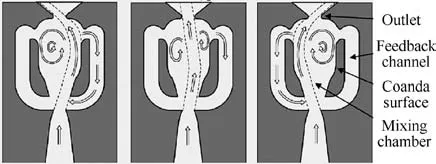
Fig. 1 Fluidic oscillator schematic and sequence of switching mechanism.4
In recent years, scholars have found that fluidic oscillators have great potential for application in drag control,4noise,5combustion,6and flow separation.7There are some applications of oscillators in aeronautics field.Woszidlo and Wygnanski7applied the sweeping jet to the flow control of the flap.Under the input of sweeping flow energy, the free flow can stick to the wall and reduce the drag. Mack et al.8arranged several fluidic oscillators side by side on the suction surface of the low-pressure turbine blade model. The Tollmien Schlichting wave was excited by the swept jet generated, and thus the boundary layer transition on the blade surface was sudden.Marcel and Wolfgang9arranged a fluidic oscillator along the chord direction on the end wall of compressor cascade. The experimental data show that the stability of the flow on the cascade surface is enhanced and the oscillating jet on the end wall expands the working range of the compressor; the static pressure on the blade increases by 6% and the flow loss decreases by 4% under the condition of no active control.NASA and Boeing10have jointly carried out wind tunnel model test of Boeing 757 vertical wake flow field active control.31 fluidic oscillators are used as active control and excitation devices are arranged on the vertical tail. At a free velocity of 100 kn(1 kn=0.514 m/s)and rudder angle of 30°,the lateral force of the vertical tail under the control of the main stream increases by 20%,which indicates that the free flow separation on the vertical tail is effectively restrained by the oscillating jet.Tewes and Taubert11arranged the fluidic oscillator on the fluid separation line of the swept wing to carry out wind tunnel test.The test results showed that the oscillating jet reduces the fluid flow in the spanwise direction,increases the wing lift,and suppresses the wing tip stall. This provides a technical way to increase the swept wing angle and increase the critical Mach number of the wing.
The flow characteristics of oscillation are different depending on the oscillator’s design, size, and supply rate. Feikema and Culley12studied the switching characteristics of the jet oscillator by defining the ratio of momentum flux of the controlled port jet to the inlet flux. It is concluded that the best switching effect can be obtained when the ratio is about 0.25,too large or too small of the ratio will weaken the switching performance of the jet oscillator. Tesar et al.13connected two control ports with a pipe.Under the action of the pressure difference between two ports,the sweeping jet is produced.The frequency of the oscillation is related to the length of the pipe.Wang and Xue14used the method of Computational Fluid Dynamics (CFD) to study the attachment and the switching performance of the internal flow, and it was concluded that the upstream flow position of the control flow has a significant influence on the wall attachment of the main jet. Bai and Ming15studied the velocity and pressure fields of the flow in a wall-attached jet element using numerical simulation and investigated its unsteady flow mechanism. It is proposed that the deflection of the main jet is caused by the pressure difference between the two sides of the main jet.The deflection characteristics of the wall jet element are related to its geometric structure and fluid Reynolds number, and the low-pressure eddy current induces the main jet to attach to the wall. Many studies on oscillators are limited to subsonic fields. Water or other incompressible liquids were used as working fluids in low Mach number environments. With the increase of the application requirement of flow-controlled fluidic oscillator,the outlet velocity of jet should be increased, accompanied by compressibility effect and high oscillation frequency.These high oscillatory frequencies are very demanding for experimental measurements. To reduce the difficulty of the experiment,either working fluid is changed from air to water16or the size of the oscillator increases, which results in the fact that the fluid velocity reduces to an incompressible low speed.17Therefore, there are few studies on supersonic jet oscillators. Seele et al.18studied the global effects of the oscillators and showed qualitative results without a detailed analysis of the internal flow field.Gokoglu et al.19carried out a preliminary numerical study of supersonic jet oscillators.Sun et al.20,21conducted the wind tunnel test under different back pressures in a vacuumtype wind tunnel for two supersonic jet oscillators, to obtain their characteristics and the conditions for jet oscillation.Some of its operation features were summarized, but further investigations and more detailed measurements are needed to discover the underlying mechanism.
Presently,most of the previous studies are conducted under low pressure ratio working conditions;the working fluid speed is low.The research work on the wall-attached oscillator is limited to subsonic, and the oscillating flow mechanism and the sweeping process are not fully understood, yet. The oscillator working under supersonic conditions is often accompanied by compressibility effect and high oscillation frequency.Under supersonic conditions, the shock wave is produced in the mixing chamber. The wall-attached fluid expands and compresses constantly, and finally decreases near to the sonic. The direct measurement of velocity is very challenging at these small scales particularly when the flow is unsteady as in a sweeping jet.As Raghu has stated,‘‘So far,there are no direct measurements of supersonic sweeping jets or pulsed jets exiting from fluidic oscillators.”22The motivation for this study comes from the desire to develop robust actuators that can function over a range from subsonic to supersonic conditions. The traditional wall-attached fluidic oscillator was novelly improved in structure to generate two alternating but independent supersonic jets. The sweeping jet was divided into two jets with varying flow rate over time by the splitter. In the exit channel, the jet was accelerated again by convergent-divergent nozzle. Therefore, the pulsating supersonic jet flowed out alternately. The specific objective of this paper is to understand working mechanisms in such a fluidic diverter actuator by a time-dependent numerical analysis.This understanding will aid in the development of fluidic oscillators with minimum pressure losses and advanced designs of flow control actuators.
2. Computational method
This section provides a brief overview of the computational setups that were used for the discussed studies. The geometrical model,the distribution of the mesh,the turbulent model for computation and the boundary conditions of the computational domain are introduced in this section.
2.1. Geometrical model
The new structure of the wall-attached fluidic oscillator proposed in this paper is shown in Fig.2.The power nozzle width is 5 mm.The inlet and outlet width of the mixing chamber are 9 mm and 16 mm respectively.The width of FBC is 4 mm.And the angle of splitter is 95°. The whole oscillator is 150 mm extended and 50 mm wide. The specific improvement of this geometric structure is the change to the outlet section of the oscillator. Because of the complex motion of the fluid in the mixing chamber, the desired supersonic fluid is often not obtained at the outlet position of the mixing chamber. Therefore, the structure of the outlet section is improved in this paper. When the jet flows out of the mixing chamber, it is divided into two jets with varying flow rate over time by the splitter. The jet flowed alternatingly from two outlets and was accelerated by the convergent-divergent nozzles in the outlet channel, thus generating supersonic jets at two outlets.
2.2. Mesh setup
Structured grids were established on the numerical model using ANSYS FLUENT. Fig. 3 shows a sample mesh of the oscillator. The near wall grids were refined to guarantee that the first grid points adjacent to the wall were placed at y+<1.For the supersonic,compressible turbulent flow cases studied here, solution-adaptive grid refinement is employed based on local pressure gradients to accurately locate the shocks and resolve the pressure amplitudes. Solutionadaptive grid generation ended up with 122452 computational cells for the supersonic cases considered.
2.3. Numerical method validation
All simulations were carried out using FLUENT 16.A secondorder implicit discretization in time has been adopted for the unsteady calculation. The flow equations were discretized by a second-order upwind scheme, which provides stability for supersonic flows and captures shocks well. Spatial gradients were reconstructed by a least-square cell-based method. The time step was set as 1×10⁻⁷s, and the residual errors of all physical quantities were kept below 1×10⁻³.
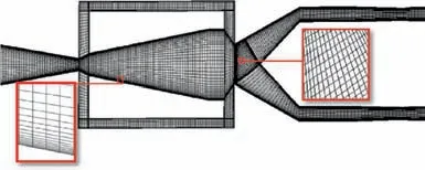
Fig. 3 Mesh distribution.
The turbulence model plays a decisive role in the results of numerical calculation. To validate the accuracy of the turbulence model, two different turbulence models were tested,namely the standard k-ε model and the k-ω Shear-Stress Transport (SST) model. Both of the unsteady computational results with k-ω SST and standard k-ε turbulence model were compared to available experimental data in Ref.23. The geometric size of the calculated model is consistent with the experimental model in the reference. The Nozzle Pressure Ratio(NPR)was defined as the ratio of supplied pressure to ambient pressure.All tests were carried out under supersonic jet conditions with the NPR various from 2 to 5.In Ref.23,quantitative measurements of the sweeping jet angle at the oscillator exit are achieved using the Canny edge-detection method via the schlieren images.The sweeping jet centerline is calculated using the straight line between the center of the selected pixel masses and the center of the nozzle throat, and it is defined as the sweeping jet angle. The maximum jet sweeping angle is determined by averaging the maximum values of the sweeping angle in each period in the wave pattern. Fig. 4 shows the variation of sweeping angle with time in one period (T). The computational results with k-ω SST turbulence model show good agreement with the experimental results in Ref.23.The oscillation frequencies under different NPRs are simulated and compared with the experimental results in Ref.23, as shown in Fig. 5. In addition to the frequency results from Fast Fourier Transform (FFT) of the pressure signal, the frequency results of the high-speed schlieren visualization are also presented,which are estimated by measuring the periods from peak to peak in the jet sweeping angle. The oscillation frequency approaches the saturation limit in supersonic flow regime.This narrower frequency band characteristic to the supplying pressure is one of the characteristics of the supersonic sweeping jet.24,25The variation trend of the frequency is consistent with the experimental results. The computational results with k-ω SST turbulence model have a smaller difference compared with standard k-ε turbulence model.Besides,as shown in the previous study, the k-ω SST turbulence model offers a more accurate treatment of the near-wall region and is reliable for the type of flows with adverse pressure gradients(such as the situation with Coanda effect) and shock waves.17Thus the k-ω SST turbulence model is applicable. Therefore, all the numerical investigations conducted in this paper are based on the kω SST turbulence model.
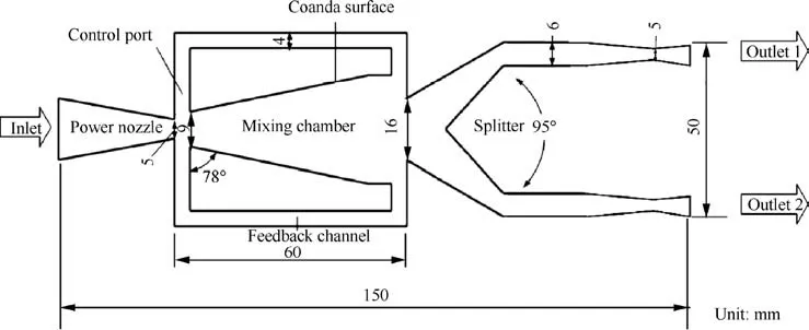
Fig. 2 Structure and geometric dimensions of fluidic oscillator.
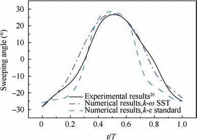
Fig. 4 Sweeping angle in one period.
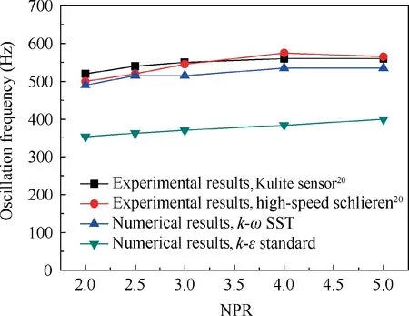
Fig. 5 Effects of NPR on frequency.
2.4. Governing equations
According to the flow characteristics of the physical problems studied in this paper, the medium is defined as ideal gas in numerical calculation.The governing equations can be written as follows:
Continuity equation
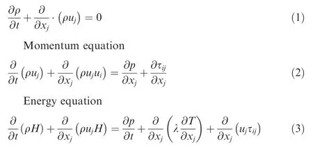
where ρ is the density,ujis the velocity in xjdirection,p is the pressure,λ is the thermal conductivity,T is the temperature,H is the total enthalpy, and τijis the stress tensor which is expressed as
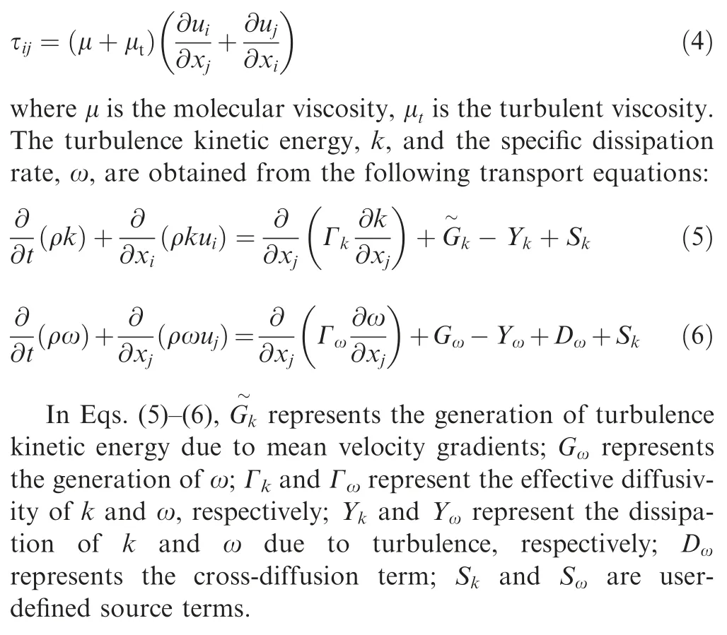
2.5. Boundary conditions
There was a pressure inlet with 3.67 atm (1 atm=101325 Pa)and 298 K at the beginning of the converging nozzle. The two outlets were opened to the ambient environment (1 atm and 298 K). For the cases considered in this paper, the Reynolds number is large enough to assume fully turbulent flow. For high-speed compressible flows, the density-based solver is the preferred option because it includes the energy equation in the coupled system, resulting in a single matrix equation to be solved. The effects of full compressibility and viscous dissipation are also properly incorporated into the model for the supersonic cases considered here. Gokoglu et al. used this method to simulate the model in Ref.25, and the relevant experiments are carried out to verify it. The numerical results show good agreement with the experimental results. To analyze the fundamental working mechanism and flow characteristics of the oscillator,it is necessary to know how the flow rate at different positions in the oscillator varies with time. Therefore, some line probes were set up in the 2-D computational model to gain the flow direction and flow rate at different time.All line probes are shown in Fig. 6. Representations of line probes are shown in Table 1.
3. Results and analysis for one period
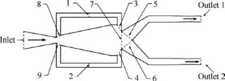
Fig. 6 Computational model and line probes distribution.
This section provides the results and analysis for one robust period of the oscillator.The section is divided into three parts.As an innovative jet oscillator,our primary goal is to generate two pulse supersonic jets at two outlets, so the first part describes the Mach number at the outlet of the oscillator. It is worth noting that the mass flow rate of the fluid in the feedback channel rises and falls repeatedly in a robust period. In order to further reveal the working process of the oscillator,the second part reveals the flow mechanism in the feedback channel of the oscillator. At the outlet of the mixing cavity,the main jet is divided,so the last part shows the flow distribution of the main jet at the outlet of the mixing chamber at different time.
3.1. Mach number
The local Mach number is a function of the pressure ratio between the local pressure p and the total pressure p0.

where γ is 1.4 in this study.The Mach number at the outlet can reach 1.5 when the gas is perfectly expanded.

where poutletis the local pressure of outlet. The internal flow losses are less prior to the oscillator start-up. Fig. 7 shows the Mach contour of the oscillator before the oscillation, and the highest Mach number at the outlet can reach 1.5.
The Mach contours in a robust oscillation period are shown in Fig. 8. The high-pressure fluid was accelerated further to Mach number 1 by the power nozzle. At 0T/6, the jet in the mixing chamber was deflected upward and attached to the upper wall of the mixing chamber. At the same time, only a small amount of fluid had just entered into the upper FBC,while the outlet of the lower FBC had a residual outflow.Under the action of the splitter, most of the main jet flowed out of the Outlet 2, resulting in a supersonic jet. At T/6, the flow in the upper FBC had reached to the outlet of the FBC.The reversed flow interacted with the main jet in the inlet junction region and pushed the jet downward. At 2T/6, the fluid flowing into the upper FBC continued to increase, and the main jet started moving to the lower wall of the mixing chamber. At 3T/6, the fluid had been wholly deflected to the lower side wall of the mixing chamber.Under the action of the splitter, most of the fluid flowed out of the Outlet 1. Here, half a cycle of the oscillation was completed. In the latter half ofthe cycle, flow statements in the oscillator were fundamentally opposed to the first half cycle.As this procedure was repeated,the sweeping jet was formed in the mixing chamber.
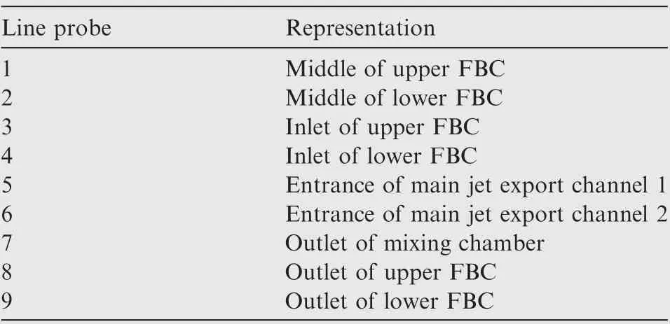
Table 1 Representation of line probes in Fig. 1.

Fig. 7 Mach contour of oscillator before starting oscillating.
The streamline of velocity in a robust oscillation period is shown in Fig. 9. There were two main recirculation bubbles in the mixing chamber during the working process of the oscillator.They play a leading role in the work of the oscillator.At 0T/6, the jet in the mixing chamber was deflected upward and attached to the upper wall of the mixing chamber.A big lower recirculation bubble was formed in the mixing chamber. At T/6,a small upper recirculation bubble was formed in the mixing chamber.The reversed flow interacted with the main jet in the inlet junction region and pushed the jet downward. At 2T/6, the upper recirculation bubble was bigger than before,and the main jet was squeezed to the lower wall of the mixing chamber. The lower recirculation bubble is obviously smaller than T/6. At 3T/6, the lower recirculation bubble completely disappeared. The fluid had been wholly deflected to the lower side wall of the mixing chamber.In the latter half of the cycle,the movement trends of two main recirculation bubbles are opposite to the first half cycle.As this procedure was repeated,the sweeping jet was formed in the mixing chamber.
The sweeping jet was divided into two jets with varying flow rate over time by the splitter. In the exit channel, the jet was accelerated again by convergent-divergent nozzle. Therefore,the pulsating supersonic jet flowed out alternately from two outlets.The Mach numbers of Outlet 1 and Outlet 2 in a stable oscillation period are shown in Fig. 10. In the period of 0T to 0.5T,the flow in the oscillator mainly flowed out of the Outlet 2. Mach numbers of the Outlet 2 were kept above 1.3 during the period of 0T to 0.5T. Although the supersonic jet is achieved at the outlet of the oscillator, there is a deviation to the theoretical value of Mach number 1.5 under this pressure ratio. There are many reasons for this deviation. On the one hand, the high-speed main jet was attached to the wall of the oscillation chamber, and the viscosity of the wall caused flow loss.At the outlet of the mixing chamber,the high-speed main jet interacted on the splitter,causing the flow loss.On the other hand, the flow area narrowed before it flowed into the convergent-divergent nozzle, making fluid accelerate and expand ahead of time, and causing flow loss.
Fig.11 shows the Mach number contours for different supply pressures(pplenum).When the velocity of the fluid inside the oscillator is below to the sonic, the velocity of the mainstream attached to the mixing chamber wall is uniform.When the supply pressure is 2.0×10⁵Pa,there is a deviation for the velocity distribution of the mainstream attached to the mixing chamber wall. With increasing supply pressure, the shock wave is produced in the mixing chamber; the wall-attached fluid expands and compresses constantly, and finally decreases near to the sonic.As shown in Fig.11,the jet is accelerated again in region A, which is caused by the sudden expansion here. When the fluid reaches to the speed of sound, the sudden expansion makes the fluid accelerate to Mach number exceeding 1. After that, as a result of a normal shock wave, the fluid falls again near the speed of sound. At two outlets, the velocity of the fluid reaches to supersonic due to the design of a convergentdivergent nozzle.
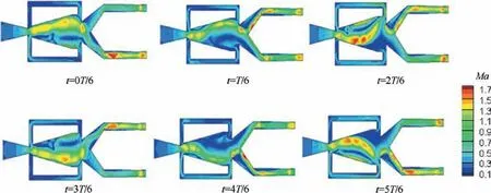
Fig. 8 Phase-resolved Mach contours.

Fig. 9 Phase-resolved streamline of velocity.
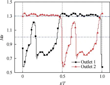
Fig. 10 Mach number of Outlet 1 and Outlet 2 in one cycle.
Total pressure recovery coefficients (σ) of the oscillator in different supply pressures (pplenum) are shown in Table 2. As shown in Fig. 12, the total pressure recovery coefficient decreases with increasing supplied pressure. This means that the collision loss inside the oscillator intensifies with the increase of jet velocity, and thus there is greater pressure loss at the outlet. Because of the complex internal flow structure inside the oscillator, it will inevitably cause large pressure losses. The purpose of this paper is to reveal its internal flow mechanism and hope to design advanced structures in the future, with smaller pressure losses under the premise of satisfying the design conditions.
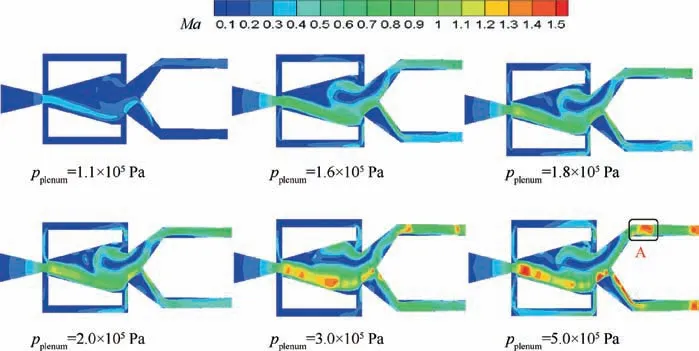
Fig 11 Mach number contours for different supply pressures.
Fig. 13 shows the effects of supply pressure on frequency.The inlet pressure varies from 1.2×10⁵Pa to 5×10⁵Pa.Gaertlein et al.17identified the transported volume through the feedback channel as the oscillation’s driving mechanism.The volume flow inside the feedback channel is only dependent on the velocities. When the wall-attached fluid reaches the speed of sound, an increasing pressure solely causes a further compression of the fluid, and the velocity of flow inside the feedback channel has no obvious change. Hence, with the increase of the pressure, the oscillation frequency saturates to a constant value.
3.2. Physical mechanism of flow inside FBC
It is worth noting that the local pressures at the inlet and the outlet of FBC were changing during the process of alternating wall attachment in the mixing chamber, and thus the flow direction in the FBC was not always the same. The direction of flow from the inlet of FBC to the outlet of FBC was defined as the forward direction.Fig.14 shows the local pressure contours when it flows forward and backward.It can be seen that the local pressure at the outlet area of FBC is higher than that at the inlet area of FBC when the fluid of FBC flows reversely,but when the fluid of FBC flows forward, the situation is just opposite. The flow direction inside the FBC is related to the change of the local pressure at the inlet and outlet of FBC.
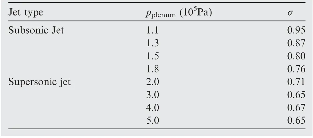
Table 2 Total pressure recovery coefficients for different supply pressures.
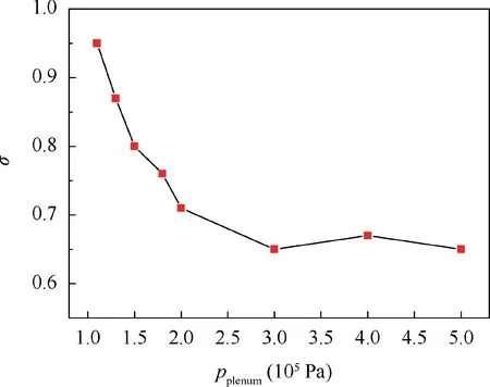
Fig 12 Total pressure recovery coefficient vs supply pressure.
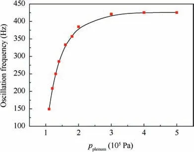
Fig. 13 Effects of supply pressure on frequency.
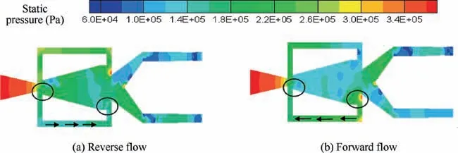
Fig. 14 Phase-resolved static pressure contours in lower feedback channel.
The mass flow rates of Line probe 1 and Line probe 2 (as shown in Fig. 6) in one cycle are plotted in Fig. 15. The negative value here indicates that the fluid in the FBC flowed from the outlet to the inlet, that is, the reverse direction as defined above. The mass flow rates of the upper and lower FBCs presented different trends at different stages. At the initial time,the mass flow rate of Line probe 1 was zero nearly, the rising trend was presented, and the mass flow rate of Line probe 2 was positive, further confirming the previous analysis that a small amount of fluid had just entered into the upper FBC.At T/6, the main jet was separated from the upper wall of the mixing chamber. As the main jet acted on the outlet of the lower FBC, the local pressure of the FBC’s outlet was increased, so that the mass flow rate of Line probe 2 started reducing. From T/6 to 2T/6, as the main jet was gradually biased toward the lower side wall of the mixing chamber, the pressure at the outlet of the lower FBC was continually increasing, causing the mass flow rate of Line probe 2 to decrease to zero. When the local pressure at the outlet of the lower FBC was higher than the inlet,the reverse direction flow occurred, and the mass flow rate increased with the rise of the outlet pressure.From 2T/6 to 3T/6,the main jet was gradually attached to the lower wall of the mixing chamber, the fluid in the inlet of the lower FBC was gradually replenished during the transition process,and the local pressure was continuously increasing.At the time of 3T/6,the jet had wholly deflected to the lower side wall,the mass flow rate of the Line probe 2 was zero, and the rising trend was presented so that the half cycle of the oscillation was completed. In the latter half period, the flow characteristics in the feedback channel were substantially opposite to the first half cycle, thus forming a complete cycle.
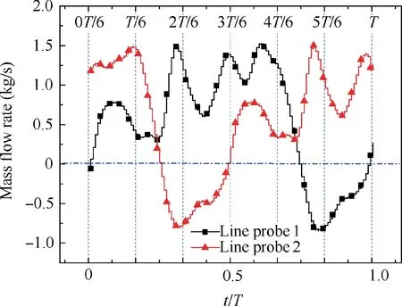
Fig.15 Mass flow rate of monitor 1 and monitor 2 in one cycle.
When the flow direction of the fluid in the FBC was different, different vortices were formed in the mixing chamber. As shown in Fig. 16(a), when the upper FBC has a reverse flow,there is outflow at the inlet of FBC.When the outflow is combined with the main jet, the flow direction of the upper FBC deflects under the effect of the main jet and flows downstream with the main jet to form a counter-clockwise vortex loop as shown in Fig. 16(a). When the fluid of the upper FBC flows forward, part of the main jet flows into the FBC. At the same time, some of the fluids collide into the upper wall of the mixing chamber outlet to fold back to the mixing chamber, thus forming a clockwise vortex loop, as shown in Fig. 16(b) A.Some of the reentrant fluids continue to interact with the main jet to form an anticlockwise vortex loop,as shown in Fig.16(b)B,and the formation mechanism of the vortex loop is the same as that in Fig. 16(a).
3.3. Mass flow rate distributions at outlet of mixing chamber
At the outlet of the mixing chamber, there was a separation phenomenon of the fluid.Most of the fluid flowed out through two outlets under the action of the splitter.A small portion of the fluid flows into the FBC.Fig.17 shows the variation of the mass flow rate of Outlet 1, Outlet 2, Line probe 3, and Line probe 4 with time. From 0 T/6 to T/6, the mass flow rate of Outlet 1 increased significantly, while the mass flow rate of Line probe 3 decreased significantly, due to the fact that the main jet began to deflect downward to the mixing chamber from the state of completely attached to the upper side wall.During deflection, the fluid attached to the upper wall of the mixing chamber was reduced compared with the initial time,so the mass flow rate of Line probe 3 was decreased. During the period from T/6 to 2T/6, the mass flow rate of Outlet 1 and Outlet 2 was decreased,and the total outlet mass flow rate was reduced, because some fluid has flowed into the lower feedback channel constantly during this time. The change of Line probe 4 during this period indicates that the flow direction at the inlet of the lower FBC has changed, the mass flow rate was gradually reduced to zero,and then the fluid began to flow from the mixing chamber to the lower FBC as flow rate increased gradually, so the reduction of the total flow rate was fed into the FBC. The flow in the lower FBC was increased further during the period of 2T/6 to 3T/6, and the fluid in the mixing chamber was gradually attached to the lower side wall, so that the mass flow rate of the upper FBC was continuously reducing, even a negative value was present,which indicates that the fluid in the FBC flowed to the mixing chamber at Line probe 3. With the lapse of time, at 3T/6, the jet had completely attached to the lower side wall.In the latter half cycle,the variation trend of the flow in the upper FBC was the same as that of the lower FBC in the previous half period.The changing trend of the mass flow rate of Outlet 1 was the same as that of Outlet 2 in the previous half period. The main jet gradually deflected to the upper side wall and had been completely attached to it at T.
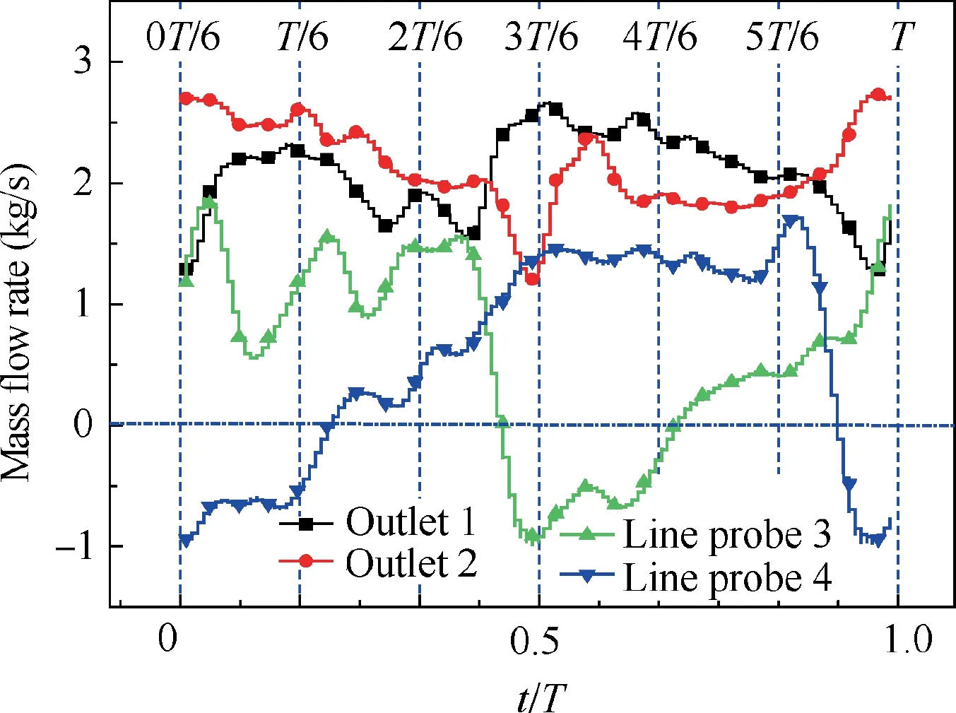
Fig. 17 Mass flow rate of Outlet 1, Outlet 2, Line probe 3 and Line probe 4 in one steady period.
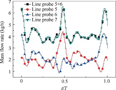
Fig. 18 Mass flow rate of Line probe 5, Line probe 6, and Line probe 7.
Line probe 5 and Line probe 6 are entrances of export channel 1 and channel 2, respectively. As shown in Fig. 18,the mass flow rate of Line probe 5 experienced valley value at the beginning and the flow rate of Line probe 6 reached the peak. At 0.5T, the flow rate of Line probe 6 had valley value, and the flow rate of Line probe 5 reached the peak.After one cycle, the flow rate was the same as at the initial time.The summation of the flow rate of Line probe 5 and Line probe 6 basically coincides with the mass flow rate of Line probe 7,which indicates that the flow at the outlet of the mixing chamber was separated into two strands by the splitter.Since the fluid entering the feedback channel was constantly changing, the mass flow rate of Line probe 7 was not always unchanged. The peak value of Line probe 7 occurred when the vast majority of the main jet flowed out of Outlet 1 or Outlet 2.
4. Conclusions
Simulations of a type of supersonic fluidic oscillator were conducted to demonstrate the feasibility of pulsating supersonic jets preliminarily. Detailed aerodynamic analysis was done on the main features of the supersonic fluidic oscillator. An analysis of the internal fluid dynamics of the fluidic oscillator suggests that the supersonic jet deflection is closely connected to the pressure distribution and mass flow rate in both FBCs.The correlation between flow direction and its switching dynamics were revealed. The findings are listed as follows:
(1) The structure of the traditional wall-attached fluidic oscillator is improved in this paper.With increasing supply pressure, the shock wave is produced in the mixing chamber.When the wall-attached fluid reaches the speed of sound, the oscillation frequency saturates to a constant value with increasing supply pressure under supersonic condition.
(2) When pressured with 3.67×10⁵Pa at the inlet, the improved oscillator flows out of supersonic jet with Mach number of 1.3 or more alternately from two outlets, and each outlet can maintain half a cycle. When a pulsating supersonic jet is produced continuously at one outlet, a small amount of fluid flows out of the other. The flow rate distribution ratio is related to the splitter position, which is the focus of further research.
(3) The flow direction of the fluid in the FBC is determined by the pressure difference at both ports. The main jet is forced to switch and attach to the upper and lower side walls of the mixing chamber due to the interaction with the fluid in the feedback channel. With different flow directions,the fluid flowing out from the FBC forms different vortices in the mixing chamber after the interaction with the main jet.
Declaration of Competing Interest
The authors declare that they have no known competing financial interests or personal relationships that could have appeared to influence the work reported in this paper.
Acknowledgements
This study was supported by the National Science and Technology Major Project (No. 2017-III-0011-0037).
 CHINESE JOURNAL OF AERONAUTICS2021年5期
- CHINESE JOURNAL OF AERONAUTICS的其它文章
- Ferrofluid moving thin films for active flow control
- Preliminary study on heat flux measurement data of TT-0 flight test
- An analysis and enhanced proposal of atmospheric boundary layer wind modelling techniques for automation of air traffic management
- Jet sweeping angle control by fluidic oscillators with master-slave designs
- Hot deformation behavior and microstructure evolution of the laser solid formed TC4 titanium alloy
- Electrochemical trepanning with an auxiliary electrode
