Analysis and control optimization of positive pressure fluctuation in electromechanical oxygen regulator
Rui PAN, Guiping LIN, Zhigo SHI, Yu ZENG,*, Xue YANG
a School of Aeronautic Science and Engineering, Beihang University, Beijing 100083, China
b Hefei Jianghang Aircraft Equipment Corporation Ltd, AVIC, Hefei 230051, China
c Beijing Institute of Spacecraft Environment Engineering, Beijing 100094, China
KEYWORDS Aviator oxygen system;Electromechanical Oxygen Regulator (EMOR);Feedforward control;Disturbance rejection;Proportional resonant control
Abstract The Electromechanical Oxygen Regulator (EMOR) is a new type of aviator oxygen equipment. Positive pressure refers to the pressure difference between the breath pressure and the ambient pressure during pressurized oxygen supply. The phenomenon of positive pressure fluctuation was believed to reduce the system performance.The current open-loop control method cannot solve this problem. In this paper, the mathematical model was established and main factors were analyzed. By combining experimental research and simulation calculation, it was determined that pressure fluctuation was caused by inlet pressure and diaphragm deformation together. With the increase of pulmonary ventilation volume, the influence of inlet pressure on fluctuation decreases gradually,while the proportion of diaphragm deformation increases rapidly.A closed-loop control strategy of Proportional Resonant with Feedforward Compensation(PRFC)was proposed to solve the problem and control parameters were obtained through co-simulation. The effectiveness of the control strategy was verified by experiments.The results show that the control strategy can enhance the anti-disturbance ability of the system and significantly reduce the pressure fluctuation range,which is beneficial to improving the overall system performance.
1. Introduction
Aviator oxygen system is a vital life-support system for jet pilots, which is referred to as ‘‘take the first place and use it all the time”.1,2Oxygen regulator, the core component of aviator oxygen system, could provide sufficient oxygen as demanded and protect pilots from physiological reactions at high altitude and G-force through positive pressure.3-5Mechanical one and electronic one are the main two types of aviator oxygen regulator.6With the application of Molecular Sieve Oxygen Generation System (MSOGS), the traditional mechanical oxygen regulator had been plagued by insufficient flow and high breath resistance. The electronic oxygen regulator developed by France operated well with MSOGS,with the advantages of high accuracy and fast response.7However,once electronic failure occurs, the electronic oxygen regulator could not guarantee the performance, leading to the limited application scope.
In recent years, the Electromechanical Oxygen Regulator(EMOR)has been proposed as a new type of oxygen regulator which is characterized by mechanical and electronic hybrid control. Through electronic pressurization technology to simplify the complicated pressurization mechanism, a new type of EMOR has been developed by China based on the design of mechanical type. It combines the advantages of mechanical reliability and electronic control.More importantly,it reduces the impact of electronic failures and could supply oxygen without power supply.8Turning to emergency oxygen supply in commercial aviation,several EMORs were designed to provide more effective protection in case of loss of cabin pressure.The electromechanical valve designed by Siska and Collins9used a movable valve seat which was actuated by an electronic motor and the EMOR applied by Robert10adopted double valves,which were controlled by mechanism and electronic motor respectively. In summary, all of the EMOR could automatically revert to a fully operational mechanical regulator in the event of an electronic failure or a power supply failure.
So far,there have been many studies related to oxygen regulator,while few of them focused on the EMOR due to its novelty and hybrid control.These studies can be separated into two different parts: mechanical analysis and design of electronic control law, providing theories and methods for the studies on EMOR. In terms of mechanical analysis, Yu11and Wan12et al. modeled several typical oxygen systems and improved the performance of oxygen regulator by optimizing key parameters.Zeng and Lin13used CFD simulation to analyze the reason of uncontrollable force on balanced valve, reducing the effects of dead zone. In terms of electronic control,Yu et al.14used switch control and Sun et al.15adapted fuzzy control to design the control law of electronic oxygen regulator.Li et al.16used expert control to adjust PID parameters automatically,solving the shortage of fixed control parameters.Jiang pointed out that disturbance rejection is the key question of oxygen regulator control.Generalized Predictive Control(GPC),17Automatic Disturbance Rejection Control(ADRC),18and adaptive control19have been applied to improve the performance, and it is found that intelligent control methods may have better robustness and rapidity than PID.
During cruise of aircraft, positive pressure is set to prevent air leakage into breath mask. The fluctuation of positive pressure was found with the breath.Positive pressure could be seen as the set point of breath pressure control and is expected to keep constant. Limited by the current open-loop adjustment method, adverse impact on system performance cannot be rejected, making pilots breath uncomfortably.
In this paper,the working principle of EMOR is introduced and the mathematical model is established. Causes of positive pressure fluctuation are discussed and obtained by simulation and experiments. According to the characteristics of these causes, the new closed-loop control method is proposed to reject the disturbance. Co-simulation between AMESim and MATLAB/Simulink is conducted to choose the proper control parameters.And the performance after control optimization is verified by experimental results.
2. Principle and problem
2.1. Working principle
The schematic diagram and component indexes of EMOR can be obtained from Fig. 1. The working principle is as follows:
(1) The EMOR consists of the breath pressure control system and the positive pressure control system. Breath pressure refers to the air pressure from the oxygen regulator to the pilot.Positive pressure refers to the pressure difference between breath pressure and ambient pressure. When the cabin altitude is within 5-8 km, positive pressure should be within the range of 0.1-0.44 kPa to prevent air leakage. When the cabin altitude becomes greater than 12 km, positive pressure shall be adjusted according to the ambient pressure to ensure that oxygen partial pressure is sufficient.
(2) Breath pressure control system consists of the dump valve 4, the return spring 5, the demand valve 7, lever 8 and diaphragm 9. Most of oxygen enriched air enters the regulator and reaches the demand valve where it applies an equal gas load to the valve flapper and piston.When the inhalation action occurs, the resultant pressure drops in the breath chamber C and sensing chamber B will cause the diaphragm to deflect the lever and let gas flow out to satisfy the demand. When the breath pressure reaches the set positive pressure or the expiratory action occurs, the diaphragm will get back and allow the demand valve close under the action of the return spring.The dump valve will open to avoid excessive output pressure in case of rapid decompression or constant flow failure.
(3) The positive pressure control system is formed by the electronic valve 1, the altitude valve 2 and the safety valve 3. A small flow of oxygen enriched air enters the positive pressure chamber A through the orifice 6 and is discharged into the ambient through the altitude valve and the electronic valve. The electronic valve is controlled by a step motor. And the altitude valve is controlled by an aneroid, which will expand according to the cabin altitude. When the positive pressure reaches the maximum, the safety valve will be opened to avoid excessive breath pressure.
2.2. Adverse effects
The EMOR is equipped with several pressure sensors to monitor the inlet pressure, the positive pressure and the breath pressure. Fig. 2 shows the data collected under multiple pulmonary ventilation volumes in the ground test.As can be seen,when there was no breath action,positive pressure and breath pressure were maintained at 0.3 kPa and 0.1 kPa respectively and the inlet pressure kept 200 kPa. During breath process,all of the pressure signals experienced continuous fluctuation,and the trend was the same.
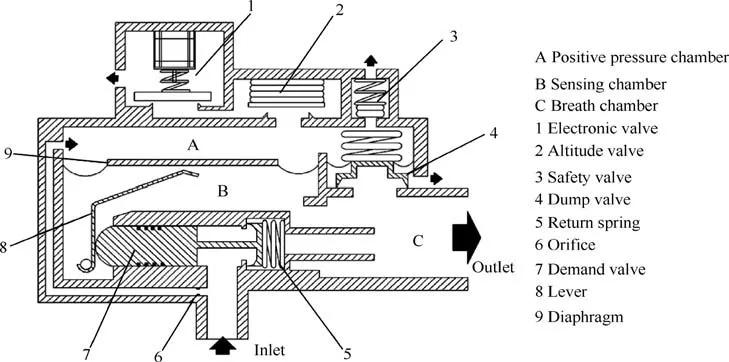
Fig. 1 Schematic diagram of EMOR.
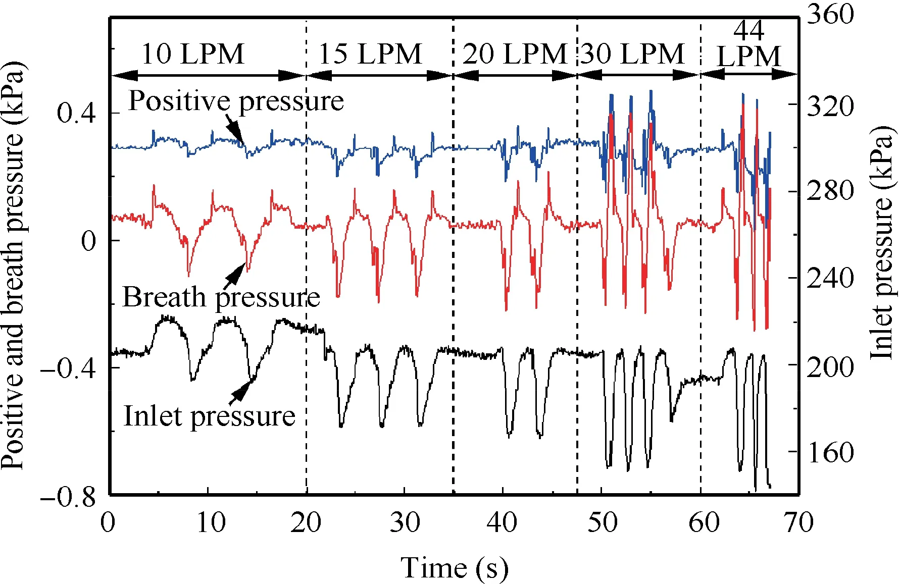
Fig. 2 Pressure fluctuation under multiple pulmonary ventilation volumes (LPM: Liter per minute).
In the studies of mechanical oxygen regulator, positive pressure was normally considered to be a constant value.Therefore, although the fluctuation phenomenon was found at the beginning of EMOR study, its effects were considered negligible. According to the working principle, positive pressure is the control target of the breath pressure and the pressure difference between two chambers is the power source of demand valve.The expected positive pressure should be a constant. However, we could find that, due to the fluctuation, the positive pressure and breath pressure reached the minimum value at the same time.The actual pressure difference becomes smaller than the expected state, leading to the decrease of diaphragm deformation and opening force of demand valve. In summary, positive pressure fluctuation may reduce the maximum supply, resulting in increased breath resistance and decreased system performance of EMOR.
3. Cause analysis
3.1. Mathematical model
The positive pressure control system has mass,energy and heat exchange with the outside and can be seen as an open system.Before establishing the mathematical model, the following assumptions were made:
(1) Gas is regarded as ideal gas and meets the ideal gas equation, of which specific heat ratio is 1.4.
(2) The process of gas flowing through positive pressure chamber and valves is very short and the heat exchange can be neglected.
(3) The pressure distribution in the chamber is even.
(4) The flow coefficients of the orifice and valves are constant.
There are mass and energy changes in control volume.The mass function is given by

where δm is the mass variation, and Ginand Goutmean inlet flow and outlet flow, respectively.
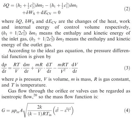
Since heat exchange between control volume and the ambient could be neglected and the potential energy difference between the inlet and outlet is quite small,the energy function can be simplified as where G is mass flow rate, μ is flow coefficient, A is flow area,pinand Tinare upstream pressure and temperature, k is the specific heat ratio,and ε is pressure ratio between downstream and upstream.The critical pressure ratio of ideal gas is known to be 0.528. If pressure ratio is smaller than the critical pressure ratio, the flow will be in the critical state, ε=εc. Otherwise, the flow will be in the subcritical state, ε=pdown/pup.
According to the principle of diaphragm deformation, the amplitude of deformation can be approximately obtained by

where x means diaphragm deformation,Δp is the pressure difference between the positive pressure chamber and the breath chamber,and Aeffand Keffare the effective area and the equivalent spring stiffness of the diaphragm respectively. The derivative of chamber volume is:

Based on the mathematical model, theoretical analysis was conducted to find the influence factors. Flow through the orifice is in the critical state and the area of the orifice is fixed,so the inlet mass flow is only determined by the inlet pressure.Flow through the valves is in the subcritical state,so the outlet mass flow is related to the positive pressure, flow area and ambient pressure. Since the absolute pressure change rate of positive pressure is relatively small, the temperature will not change significantly so that the influence of the temperature term can be ignored. The volume of the positive pressure chamber is small and the diameter of the diaphragm is large.Under the action of pressure difference, the diaphragm will be deformed and the volume may change significantly. Thus,it can be concluded that, when the ambient pressure remains constant, the main factors affecting the positive pressure include inlet pressure, outlet flow area and diaphragm deformation.
To determine the influence of each factor,the mathematical model was built and simulated based on AMESim, which is shown in Fig. 3. AMESim provides advanced modeling environment for performing simulation of engineering systems.21The components used in the model were mainly chosen from the pneumatic and mechanic library. PNCH011-variable volume pneumatic chamber with polytropic law was selected for the chamber model, PPAD001-pneumatic diaphragm without volumetric stiffness was selected for the diaphragm model and PNAP032-pneumatic flapper nozzle valve was selected for the valve model. In view of the ground test condition,the ambient parameters were set at 101.325 kPa, 293.15 K and the altitude valve was kept fully open, which has no impact on the positive pressure control. The main structural parameters are shown in Table 1.
3.2. Results and discussion
3.2.1. Effect of inlet pressure
Limited by the operating characteristic of inlet pressure reducer, when the supply flow changes significantly, the inlet pressure will change inevitably. Simulation and experiments were carried out respectively to study the effect of inlet pressure on positive pressure. In experiments, inlet pressure was adjusted manually by the inlet pressure reducer between 120 kPa and 230 kPa with electronic valve unchanged and no breath action.The variation of positive pressure was recorded.In simulation, the outlet flow area was kept unchanged, the diaphragm was set static,and the inlet pressure was set as same as the pressure curve from the experiment. The inlet pressure and the comparison between simulation and experimental results are shown in Fig. 4.
It can be seen from Fig.4 that the simulation results are in good agreement with the experimental results. Thus, the characteristics of positive pressure control system can be reflected by the model accurately. For every 100 kPa increase of inlet pressure, the positive pressure increased by 0.205 kPa without any other factors. The variation trend of positive pressure is linear and has good follow-up with inlet pressure. In order to determine the effect ratio of inlet pressure, the actual peak and valley values of inlet pressure and positive pressure at different pulmonary ventilation volumes were extracted from the fluctuation process as shown in Fig. 2. According to the inlet pressure range in fluctuation, the peak and valley values of positive pressure affected by inlet pressure were found out.Fig.5 shows actual and affected results at different pulmonary ventilation volumes. We could find that at small pulmonary ventilation volume, the effect ratio of inlet pressure is about 50%. With the increase of pulmonary ventilation volume,though the affected range increased slightly, the effect ratio decreased to about 20%. Thus, it can be inferred that inlet pressure might be a secondary cause of fluctuation. There are still some other factors causing severe fluctuation of positive pressure at high pulmonary ventilation volume.
3.2.2. Effect of outlet flow area
The outlet flow area is controlled by adjusting motor displacement. Simulation and experiments were carried out respectively to study the effect of outlet flow area. The design conditions of experiment and simulation are the same:the inlet pressure was kept unchanged at 200 kPa, the diaphragm was set static (no breath action), motor displacement was adjusted within stroke, and positive pressure was recorded. The comparison between the simulation results and the experimental results is shown in Fig. 6.
With the increase of motor displacement, the outlet flow area decreased and positive pressure increased gradually.Meanwhile, the error between the experiment and simulation increased as well. Motor displacement has a good linear relation to positive pressure. According to the steady-state force analysis, the increasing error may come from the inaccuracy of spring stiffness or the dimension data of valve, because the slope of two curves are not the same. However, the simulation results were acceptable since the dead zone of the valve was simulated and the error at small positive pressure was relatively small. In the process of positive pressure fluctuation,due to the open-loop adjustment method,the motor was maintained at a fixed position and the outlet flow area was kept unchanged. So, it can be concluded that the effect of outlet flow area on positive pressure fluctuation can be eliminated.
3.2.3. Effect of diaphragm deformation
When pilot breathes, the diaphragm will deform and make a significant effect on the volume of the positive pressure chamber. Due to the compact structure of the EMOR, it is difficult to add micro displacement sensors to carry out experiments.Therefore, the effect of diaphragm deformation was analyzed by simulation.
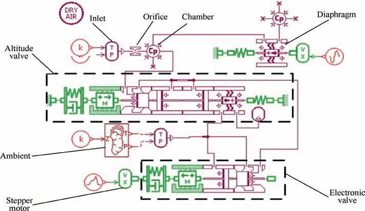
Fig. 3 Mathematical model of EMOR in AMESim.
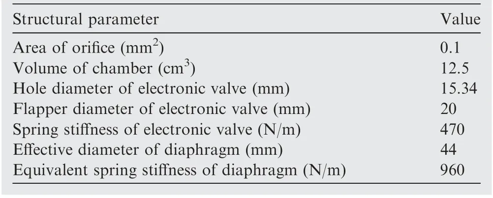
Table 1 Structural parameters.
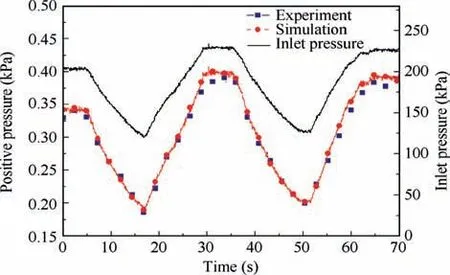
Fig.4 Comparison between simulation and experimental results with inlet pressure.
According to the recorded data, the pressure difference curve at two ends of the diaphragm was approximately sinusoidal.Therefore,the diaphragm deformation was set as a sine curve with different periods and amplitudes. Three periods with responding amplitudes were studied in simulation. Simulation results are shown in Fig. 7. It can be seen that periodic deformation of the diaphragm will lead to significant positive pressure fluctuation. The amount of upward fluctuation was more obvious than the amount of downward fluctuation.The reason is that in the upward fluctuation, the diaphragm will depress into the interior of the positive pressure chamber,resulting in smaller volume of chamber. With the increase of pulmonary ventilation volume,the fluctuation range increased rapidly.Based on the study of inlet pressure,it can be inferred that the diaphragm deformation should be the main factor causing the positive pressure fluctuation.
3.2.4. Simulation of positive pressure fluctuation
To determine the couple effects of inlet pressure and diaphragm deformation, the simulation of positive pressure fluctuation was carried out. The recorded data of inlet pressure and the pressure difference between the two chambers in Fig. 2 were taken as the dynamic input conditions. The comparison between the simulation results and the experimental results is shown in Fig. 8. The RMSE index was used to analyze the error and the peak and valley values are compared in Table 2.
From Fig.8,we can find that simulation fluctuation results are basically consistent in response speed and fluctuation range but do not match well with the actual experimental results precisely. The RMSE index showed that the error of simulation was relatively big and increased with the pulmonary ventilation volume. However, the simulation valley and peak values were close to the experimental results. After comparing the results, we can find that there were time delays between the peaks of simulation and experiment, resulting in large RMSE index.The cause of time delays might be that the model of diaphragm deformation is a simplified steady-state model and did not take the dynamic characteristics into consideration,resulting in the loss of mechanical process. Simulation results could reflect the couple effects but fail to simulate the dynamic response accurately. And the simulation results were still thought to be acceptable because we think that the fluctuation phenomenon could be reflected and the fluctuation range was fairly accurate.
Therefore,it can be concluded that the phenomenon of positive pressure fluctuation was caused by both the fluctuation of inlet pressure and the deformation of the diaphragm.At small pulmonary ventilation volume, the effects of two causes are similar. While at high pulmonary ventilation volume, diaphragm deformation becomes the main cause that resulted in significant positive pressure fluctuation.
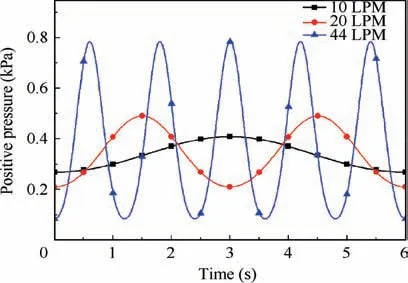
Fig. 7 Positive pressure with different periods of diaphragm deformation.
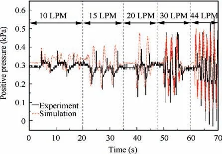
Fig.8 Comparison between simulation and experimental results of positive pressure fluctuation.
The range of positive pressure fluctuations can be reduced by two ways. Firstly, it is a direct and effective method to change the system structure, such as increasing the volume of the positive pressure chamber or adjusting the size of the diaphragm. However, this approach can also lead to changes in the system performance, which is against our purpose. Secondly, the current open-loop adjustment method can be improved to control the flow area of the electronic valve.With the real-time acquisition signal and proper control method,the effect of inlet pressure and diaphragm deformation could be rejected or suppressed. The second method can make good use of the hybrid control advantages of EMOR.
4. Control optimization
4.1. Transfer function
Due to nonlinearity of pressure control,22,23the linearization method was used to obtain the transfer function of positive pressure control near the steady-state point.Based on the conclusion of cause analysis, we wanted to obtain transfer functions relating to outlet flow area, inlet pressure and diaphragm deformation respectively.
First,only the effect of outlet flow area on positive pressure was considered. Assume that there is a small disturbance applied near the steady-state point, and Eq. (3) can be written as

where p0and δp mean the steady pressure and the small increment of pressure respectively, Gout0and ΔGoutare the outlet flow at steady state and small increment of outlet flow.
Since inlet flow is decided by inlet pressure,the increment of Ginwas ignored. By subtracting Eq. (3) from Eq. (7), the inlet flow can be eliminated. Expand the outlet flow by Taylor formula and preserve linear terms, and then the linearization model is given by

where

Table 2 Error analysis of simulation results.

In the differential equation of diaphragm deformation and positive pressure,the state of the volume and mass in chamber cannot be eliminated and volume is coupled with pressure.Therefore, the transfer function is time-variation and could not be described accurately.Therefore,the effect of diaphragm was described by an uncertain function with some known information.
4.2. Control strategy design
To reject the disturbance caused by inlet pressure and diaphragm deformation,we designed the control strategy according to the characteristics of disturbance. The effect of inlet pressure can be seen as the input disturbance,which is measurable and could be synchronously suppressed disturbance by applying feedforward compensation based on inverse model.However, diaphragm deformation is unmeasurable and difficult to describe the transfer relationship accurately, so it was considered as the uncertain load of the system. Due to relationship with breathing action, diaphragm deformation also has approximative sinusoidal specialty. Proportional resonant control is one of effective methods to suppress the sinusoidal load disturbance at specific frequency. Thus, we decided to reject the pressure fluctuation at high pulmonary ventilation by resonant part, and use proportional control to reject the pressure fluctuation at low pulmonary ventilation. In this paper,a control strategy of Proportional Resonant with Feedforward Compensation (PRFC) was designed. Co-simulation based on AMESim and Simulink was carried out based on the established AMESim model and the control components in Simulink, which can improve the accuracy of the simulation.24,25The framework of control system in simulation is shown in Fig. 9.
Feedforward control is widely used in combination with either PID or resonant controllers. The starting point for feed forward compensation is that the feedforward variables used are either directly measured or estimated. The effects of these variables are eliminated in the control signal by a compensator.26The gain of feedforward compensation is obtained by
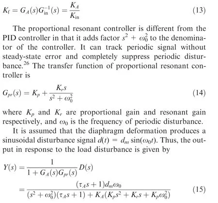
According to the final value theorem, we obtain:
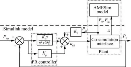
Fig. 9 Co-simulation framework of PRFC control.

The zero output in response to the load disturbance means that the load disturbance will be completely rejected by the closed-loop feedback control system at the steady state. The values of Kpand Krcan be obtained by making the characteristic polynomial of closed-loop equal to the desired closed-loop characteristic polynomial.
4.3. Co-simulation results
Co-simulation analysis was carried out based on AMESim and Simulink. To evaluate the performance of PRFC controller, a traditional PID controller was designed by pole-placement method for comparison.The parameters were adjusted slightly based on the theoretical value calculated in Section 4.2 and are shown in Table 3.
Fig.10 shows the performance comparison among the original state, PID control and PRFC control. Performance at 44 LPM is enlarged in Fig. 10. As can be seen:
(1) Compared to the original open-loop control,the closedloop control of PRFC control and PID control make the fluctuation range obviously reduce. For less than 30 LPM pulmonary ventilation volume,the dynamic errors of two control methods are almost zero and the fluctuation phenomenon are almost completely eliminated.
(2) For all pulmonary ventilation volume, performance of PRFC control was better than PID control and the disturbance was more effectively suppressed.
(3) At the maximum pulmonary ventilation volume,beneficial from the targeted rejection of high-frequency disturbance, the advantage of PRFC control is the most obvious. The downward fluctuations are 0.09 kPa of PRFC control, 0.16 kPa of PID control and 0.28 kPa of open-loop control.
Co-simulation results show that the PRFC control can optimize the positive pressure fluctuation.
4.4. Optimization experiment
On the basis of the above simulation study, experiments were carried out to verify the actual performance of PRFC control.Before applying the PRFC control strategy to the controller of EMOR, the control strategy was discretized through bilineartransformation to avoid algebraic loops. The discrete control output was applied to the control software and the control performance was obtained by the data recorder. The design of optimization experiment was as the same as the ground test of EMOR as shown in Fig. 2: inlet pressure at 200 kPa, and positive pressure at 0.3 kPa when there is no breath action.The goal of control software was to keep the positive pressure at 0.3 kPa under different pulmonary ventilation volumes.
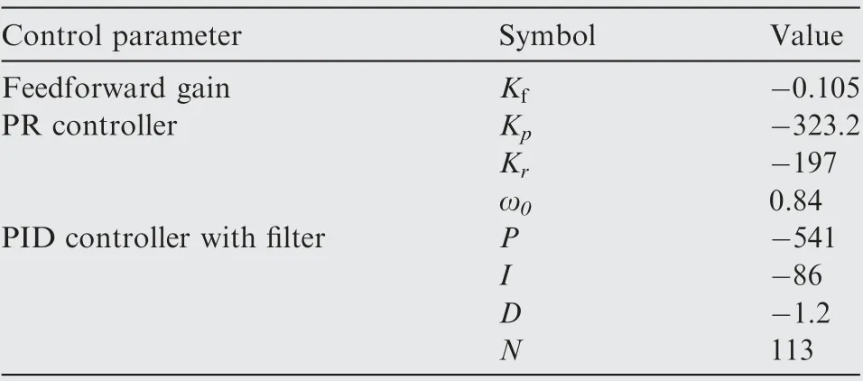
Table 3 Control parameters.

Fig. 10 Comparison of performance of different control strategies.
However,when the pulmonary ventilation was less than 30 LPM,the performance of PRFC control strategy in the experiment was not as good as expected.After checking the control input, we find that the step motor hardly moves during the process which is similar to the original state.The reason is that the theoretical control input is too small to be more than the minimum step of motor, resulting in no change in the actual control input. When pulmonary ventilation volume increased,the theoretical control input can be reflected in the actual motor step. The PRFC control strategy started to improve the control performance and pressure stability.The experimental results and actual control input at 44 LPM are shown in Fig. 11.
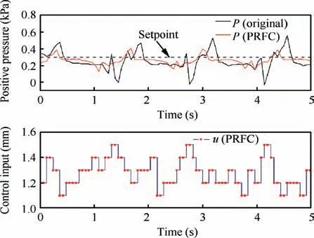
Fig. 11 Experiment performance and control input at 44 LPM.
The valley value was effectively raised from 0.01 kPa to 0.15 kPa, which means that the demand valve could provide more oxygen during inhalation. The standard deviation of two curves were calculated: 0.109 of original state and 0.051 of PRFC control.So,after control optimization,positive pressure stability has been improved significantly.According to the recorded breath pressure data, the range of pressure fluctuation in the breath chamber was reduced effectively from 0.72 kPa to 0.54 kPa. Therefore, it can be concluded that PRFC control optimization could play an important role in improving system performance.
5. Conclusions
(1) The effect of positive pressure fluctuation is discussed in this paper, which will lead to higher breath resistance and worse performance of EMOR.
(2) The causes of positive pressure fluctuation are analyzed by experiments and simulation. The simulation results are in good agreement with experimental data.
(3) The fluctuation of inlet pressure and diaphragm deformation cause the fluctuation of positive pressure together. When the pulmonary ventilation volume is small,the ratio of the two factors is close.When the pulmonary ventilation volume increases, the diaphragm deformation becomes the main cause.
(4) In this paper, a control strategy of proportional resonant with feedforward compensation (PRFC) is designed to reject disturbance.The co-simulation results show that PRFC control can obviously reduce fluctuation range.
(5) The actual performance is verified by experiments. At high pulmonary ventilation volume, control optimization is effective for stabilizing positive pressure and enhancing the performance of EMOR.
In the future work,the optimization of the system structure will be taken into consideration. And several advanced intelligent control theories are also planned to adopt. The study in this paper provides an effective method for the future research of EMOR, which is helpful to shorten the design cycle and promote the continuous optimization of EMOR.
Declaration of Competing Interest
The authors declare that they have no known competing financial interests or personal relationships that could have appeared to influence the work reported in this paper.
 CHINESE JOURNAL OF AERONAUTICS2021年5期
- CHINESE JOURNAL OF AERONAUTICS的其它文章
- Ferrofluid moving thin films for active flow control
- Preliminary study on heat flux measurement data of TT-0 flight test
- An analysis and enhanced proposal of atmospheric boundary layer wind modelling techniques for automation of air traffic management
- Jet sweeping angle control by fluidic oscillators with master-slave designs
- Hot deformation behavior and microstructure evolution of the laser solid formed TC4 titanium alloy
- Electrochemical trepanning with an auxiliary electrode
