Laser joining of CFRTP to titanium alloy via laser surface texturing
Ciwng TAN, Jinhui SU, Ziwei FENG, Yifn LIU, Bo CHEN,Xioguo SONG,*
a State Key Laboratory of Advanced Welding and Joining, Harbin Institute of Technology, Harbin 150001, China
b Shandong Provincial Key Laboratory of Special Welding Technology, Harbin Institute of Technology at Weihai, Weihai 264209, China
KEYWORDS Carbon fiber reinforced thermoplastic composite(CFRTP);Grid depth;Laser joining;Laser texturing;TC4
Abstract Grid pattern was textured on Ti-6Al-4V alloy (TC4) substrate surface by nanosecond laser system. Laser joining of carbon fiber reinforced thermoplastic composite (CFRTP) to TC4 joints were performed, and the effect of texture grid depth was investigated. The contact angle of molten CFRTP on textured TC4 surface was measured and the tensile-shear force was tested.The fracture surface and interface morphology were observed.The results indicated that the wettability of molten CFRTP on TC4 surface improved remarkably after laser textured TC4.Shear force of CFRTP/TC4 joints was increased by 156%after laser textured TC4 surface.When the depth of grid was deeper than 100 μm, contact angle increased and incomplete filling of molten CFRTP in grid occurred, the shear force thus decreased gradually. Resin-carbon fibers mixture was adhered on the fracture surface of TC4, and the variation tendency of adhesion ratio was consistent with that of shear force. TC4 matrix was exfoliated from substrate and adhered at the fracture surface of CFRTP,indicating stronger mechanical interlocking occurred at the joining interface after laser textured TC4 surface. Beside mechanical interlocking, compound layer consisted of CTi0.42V1.58 carburization phase was also confirmed at interface,suggesting that chemical bonding also occurred at the joining interface.
1. Introduction
Ti-6Al-4V alloy (TC4) with excellent fracture toughness and low weight have attracted the attention in aerospace industry.1-5Carbon fiber reinforced thermoplastic composite(CFRTP) was considered as the alternative material due to remarkable specific strength and corrosion resistance in aerospace and automotive engineering applications.6,7The CFRTP/TC4 joints have been extensively employed in aviation apparatus.8-10High-strength joining of CFRTP and TC4 will further achieve weight reduction but also widen these materials utilization in other fields.11-13
Nevertheless, significant difference in thermophysical characteristic cause great challenge in joining these two materials.14,15Currently, adhesive bonding, mechanical joining and welding were mainly employed in joining of CFRTP to metal.16-27Among all the joining technologies employed to date, laser joining with high efficiency and few defects was widely applied in automatic processing industry.28
In our previous studies, CFRTP and TC4 sheets were successfully joined by laser, the mechanical interlocking phenomenon of molten resin embedded into the uneven TC4 surface was discovered and compound layer was also confirmed at the joint interface.29,30This indicated the bonding mechanism of CFRTP to TC4 not only included mechanical interlocking but also chemical bonding. The mechanical interlocking remarkably affected the joining strength of CFRTP/TC4 specimens.31Generally, expanding contact area and increasing wettability of molten CFRTP substate on TC4 surface could enhance mechanical interlocking.32Laser texturing process was regarded as a surface treatment method with high efficiency and high precision, which was widely adopted in joining of metal to CFRTP process.33,34Dong-Jun Kwon et al. bonded carbon fiber reinforced epoxy composites(CFREC) with sanded aluminum.35The results indicated that the micro texture prepared by sanding process improved the wettability of the adhesive on aluminum surface and the joining strength raised approximately 5 times, which confirmed feasibility of enhancement of joining strength of metal to CFRTP by micro texture.Zhang et al.prepared different densities of convex structures on A7050 aluminum alloy by highspeed laser texturing system and joined with carbon fiber reinforce polyamide 6 (CF-PA6) by laser heat conduction joining process.36Compared with the untreated A7050 aluminumalloy, the joining strength of CF-PA6/A7050 aluminum alloy under the case of laser textured A7050 aluminum alloy surface improved from 8.5 MPa to 39 MPa. This phenomenon suggested that the joining strength of CFRTP/metal joints could improve significantly by laser textured metal surface before laser joining process. Rodrı´guez-Vidal et al. studied the effect of aspect ratio of laser texture grid at low alloy steel HC420 on laser joining fiberglass reinforced polyamide 6 composite material (PA6-GF30) to low alloy steel HC420.37They found that aspect ratio within a certain range could improve the joining strength. However, little effect for joining strength was investigated after aspect ratio exceeded the limit.

Table 1 Nominal chemical compositions of titanium alloy TC4.
Till now, most previous studies mainly focused on performance modulation of CFRTP/metal joints, and reported that laser textured morphology on metal surface significantly affected the CFRTP/metal joints strength. Grid depth, a parameter of laser texturing morphology, affected the interfacial contact area. However, the influence of grid depth on strength optimization and joining mechanism in laser joining CFRTP to laser textured TC4 surface were not completely comprehended. Consequently, the objective of the present study is to discuss the effect of laser texture grid depth at TC4 surface on joining mechanism and laser joining strength of CFRTP/TC4 joints. The interfacial morphology was observed and the contact angle was measured, the joining mechanism was revealed in this study.
2. Experimental procedures
2.1. Materials
The substrate materials used were titanium alloy TC4(30 mm×50 mm×1.5 mm) and carbon fiber reinforced thermoplastic composites (CFRTP). The CFRTP consisted of polyether ether ketone resin and 30wt% short carbon fibers(25 mm×50 mm×2 mm). The melting point of CFRTP is 340°C and the temperature of decomposition is 460°C,which were supplied by Jiangsu Junhua High Performance Specialty Engineering Plastics (PEEK) Products Co., Ltd. The nominal chemical compositions of titanium alloy TC4 are presented in Table 1. The mixed acid containing 80vol% water, 15vol%hydrochloric acid and 5vol% hydrofluoric acid was adopted to remove the oxide layers on TC4 sheet surface before laser texturing. The textured TC4 sheets and CFRTP sheets were cleaned with the mixture of acetone and alcohol by JP-010T ultrasonic cleaner before laser joining.
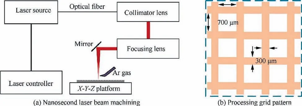
Fig. 1 Sketch of laser texturing system.
2.2. Laser texturing
The surface of TC4 sheets were textured by 70 W pulsed fiber laser system (SP070P-A-EP-Z-B-Y) with a 1064 nm wavelength, which was manufactured by HAN’S LASER (Shenzhen, China). The beam diameter was approximately 14 μm.The pulse width was 2 μs and the maximum pulse energywas 0.87 mJ. Fig. 1(a) shows the schematic diagram of laser texturing with the condition of Argon shielding gas. The laser texture pattern on TC4 sheet surface was set as grid with 300 μm width and the space of each machined groove was 700 μm as present in Fig.1(b).In order to ensure the precision of textured pattern morphology and efficiency of laser texturing process,numerous pre-experiments about variation of laser texturing parameters including frequency,laser power,defocus distance and travel speed were carried out.The optimized laser texturing parameters employed in this work are summarized in Table 2. In this study, the depth of laser texture grid was controlled by the scanning times of nanosecond laser beam, and the substrate morphologies of four cases were obtained by super depth optical microscopy (OM, DSX510) as shown in Fig.2.Melting and evaporation of the surface material caused burrs and recast layer generated around the texture grid.38
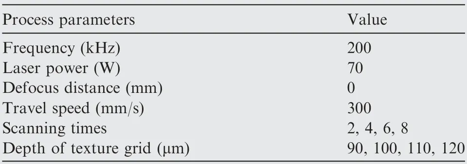
Table 2 Parameters employed in laser texturing TC4 sheets surfaces.
2.3. Laser joining
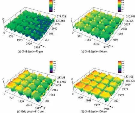
Fig. 2 Observation of surface morphology with variation of grid depth.
An IPG-6000 fiber laser system with maximum output power of 6000 W,laser beam wavelength of 1070 nm and mrad beam parameter of 8 mm product was employed in this work. Lapjoint configuration with 20 mm lap width was adopted between laser textured TC4 surface and CFRTP as shown in Fig. 3. In order to ensure the close contact of two sheets, a cylinder was used to provide a 0.5 MPa fastening force during the joining process. Based on the previous preliminary experiments, tight bonding could not be achieved under lower heat input, while a large number of spatters and pores defects occurred under higher heat input.Therefore,the optimized joining parameters were obtained in our previous studies, which are listed in Table 3.29,30All the laser joining processes were operated in Argon shielding gas to prevent oxidization.
2.4. Analysis methods
DSX510 optical microscopy (OM) and MERLIN Compact field emission scanning electron microscopy (SEM) were employed to observe the cross-sectional and typical fracture surface morphology. The elements distribution near the interface were analyzed by Energy Dispersive Spectrometer(EDS),and the interfacial phases composition were confirmed by DX-2700 X-ray diffraction (XRD) phase identification on the CFRTP/TC4 typical fracture surface. Wetting experiments were performed in RHTH 50/5018S high temperature contact angle measuring system under atmospheric conditions. Three CFRTP substrates in each case with the volume of 2 mm×2 mm×2 mm were placed on the untreated or textured TC4 surface. The stable contact angles were collected and measured when the temperature of experimental environment was 400°C which was in the CFRTP melting range.The shear force of joining specimens was measured by lap tensile tests with Instron 5967 universal testing system at room temperature.In order to guarantee parallel between joint interface and loading direction, heel blocks were adopted at the end of joining specimens as shown in Fig. 4. Three samples under same case with 0.5 mm/min crosshead tensile-shear test speed were measured and the average tested forces were calculated to improve the accuracy.

Table 3 Laser joining parameters.
3. Results and discussion
3.1. Macroscopic morphology
Fig. 5 shows the macroscopic morphology of CFRTP/TC4 joint. The laser scanning area could be obviously observed due to the laser energy absorbed by upper surface of TC4 sheet as shown in Fig.5(a).Good joint surface appeared on the TC4 sheet surface obtained in optimized process parameters. No obvious heat effect was observed in the back macroscopic morphology of CFRTP/TC4 joint. Pores and defects could not be detected as indicated in Fig.5(b).The macroscopic morphologies were similar in four cases due to the same laser joining process parameters.
3.2. Microstructure
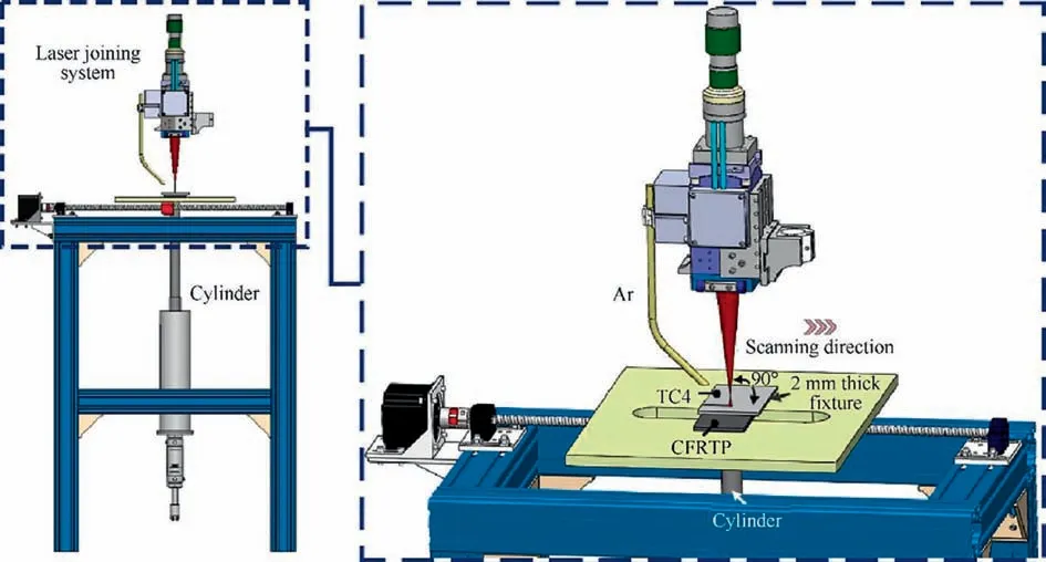
Fig. 3 Schematic diagram of laser joining of CFRTP to TC4.
Fig. 6 presents the cross-sectional optical morphology of CFRTP/TC4 joint under various depths of laser texture grid on TC4 surface. As expected, the phenomena of mechanical interlocking were more obvious after laser textured TC4 surface compared with untreated specimens in our previous studies.29When the depth of texture grid on TC4 surface was deeper than 100 μm, the melted resin could completely fill in the texture grid as shown in Fig. 6(a) and (b). However, the incomplete filling phenomenon occurred at the interface under the condition of texture depth of 110 μm and 120 μm.The area of incomplete filling gradually increased as the grid depth increased as shown in Fig. 6(c) and (d). This phenomenon was related to the wettability of molten CFRTP on TC4 surface. Fig. 7 illustrated the variation of CFRTP contact angle on TC4 substrate with various texture grid depths. Obviously,all the textured TC4 surfaces revealed more affinity for CFRTP substrate compared with the untreated TC4 substrate surface, the contact angle decreased from 111.2° to approximately 60° after laser texturing. The CFRTP contact angle firstly decreased when the texture grid depth increased from 90 μm to 100 μm. The minimum contact angle was 56.3° at the texture grid depth of 100 μm,which demonstrated the optimum affinity behavior for molten CFRTP was discovered for the TC4 substrate with 100 μm texture grid depth. When the texture grid depth continued increased, the CFRTP contact angle gradually increased. This phenomenon indicated that the wettability of CFRTP substrate on textured TC4 substrate decreased, and the filling capacity of molten CFRTP decreased, incomplete filling of CFRTP occurred as corresponded in Fig. 6(c) and (d).
Fig.8(a)shows the SEM image at the local interfacial interlocking region in the case of texture grid depth of 100 μm.The melted CFRTP flowed into the texture grid and the mechanical interlocking occurred. The element distribution across the interface of laser texturing space and grid were operated by EDS line scanning and the scanning results are exhibited in Fig.8(b)and(c),respectively.The diffusion of C,Ti and V elements could be found at the two interface positions. 12 μmthick and 10 μm-thick diffusion layers formed at the interfacial area, which indicated that a new compound could form between the TC4 substrate and molten CFRTP during the laser joining process. The XRD phase identification result on typical fracture surface is exhibited in Fig. 8(d). Carburized compound phase CTi0.42V1.58was indexed, suggesting the chemical reaction occurred at the joining interface. This phenomenon suggested that the C element in molten CFRTP could diffuse to the textured TC4 substrate under the relative high temperature, the CTi0.42V1.58carburized phase was thus formed.39The same phase was also confirmed in our previous studies.29,30Similar compound layers composing of TiS2and TiC were demonstrated in the study of Su et al.40
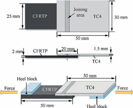
Fig. 4 Schematic diagram of tensile-shear test on CFRTP/TC4 laser bonded joint.

Fig. 5 Macroscopic morphology of laser joined joint of CFRTP to TC4 with 100 μm-depth grid.
3.3. Mechanical properties
Since the lap-joint configuration were adopted in tensile-shear test,the shear force in same size was more suitable to evaluate the joining strength of the specimens.41,42Fig. 9 shows the tested tensile-shear force of CFRTP/TC4 joints under various texture grid depth on TC4 surface.As expected,the shear force of CFRTP/TC4 joint increased significantly after laser textured TC4 surface. The shear force of specimens without laser texturing was 1023 N, while the shear force increased by approximately 156% after laser textured TC4 surface joining specimens. The fracture load gradually increased as the laser texture grid depth increased from 90 μm to 100 μm. The fracture load attained maximum of 2621 N at the laser texture grid depth of 100 μm, reaching 78.3% of that of the CFRTP base matrix.After TC4 surface textured by laser,the residual stress in TC4 surface converted from tensile residual stress to compressive residual stress, which could further promote the improvement of joining strength.43The fracture load decreased to 2160 N at the laser texture grid depth of 120 μm as the laser texture grid depth further increased. This was associated with the incomplete filling and poor wettability of molten CFRTP on the deeper texture grid of TC4 sheet surface as shown in Figs. 6(c), (d) and 7.
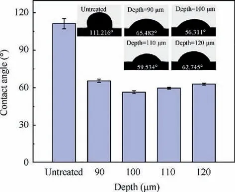
Fig. 7 CFRTP contact angle on textured TC4 surface under various grid depths.
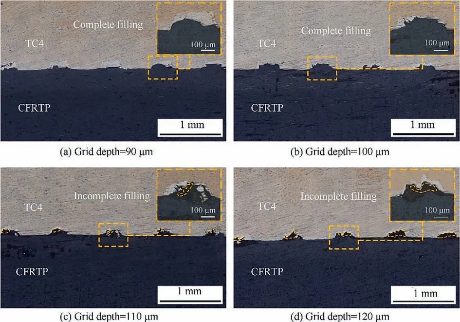
Fig. 6 Optical morphology of laser joined CFRTP/TC4 joints near interface under various texture grid depth on TC4 surface.
Typical fracture surface optical 3D morphology of TC4 side and CFRTP side of laser joining specimens with untreated and laser textured TC4 surfaces are presented in Fig.10.Adhesion of residual resin-carbon fibers mixture could be observed on both sides of laser joining area in TC4 side fracture as shown in Fig. 10(a), (c), (e), (g) and (i). This phenomenon was associated with the temperature field distribution of TC4 sheet during the laser joining process.The interfacial temperature was much higher than the melting interval of CFRTP,which caused evaporation of a large number of CFRTP.Thus,TC4 and CFRTP could not be tightly bonded. However, the interfacial temperature could melt the CFRTP in both sides of laser scanning area, TC4 and CFRTP achieved the reliable joining. Image J software was employed to comprehensively calculate the adhesin ratio of resin-carbon fibers mixture in TC4 and CFRTP fracture surface. The adhesion ratio of resin-carbon fibers mixture increased significantly after laser textured TC4 surface. With increasing texture grid depth, the adhesion ratio of resin-carbon fibers mixture first increased and then decreased as exhibited in Fig. 10(b), (d), (f), (h) and(j). The variation was consistent with the undulation tendency of tensile-shear force.When the texture grid depth was 100 μm,the adhesion ratio of resin-carbon fibers mixture reached the maximum of 58.6%. This phenomenon suggested that joining strength correlated with the adhesion ratio of resin-carbon fibers at the bonding region.
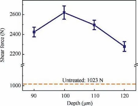
Fig. 9 Tensile-shear test result under various laser texture grid depth of TC4 surface.
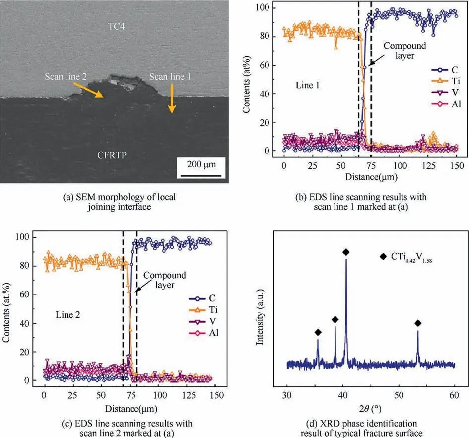
Fig. 8 SEM morphology, EDS element distribution result and XRD phase identification at local interface under case of laser textured TC4 surface with 100 μm-depth grid.
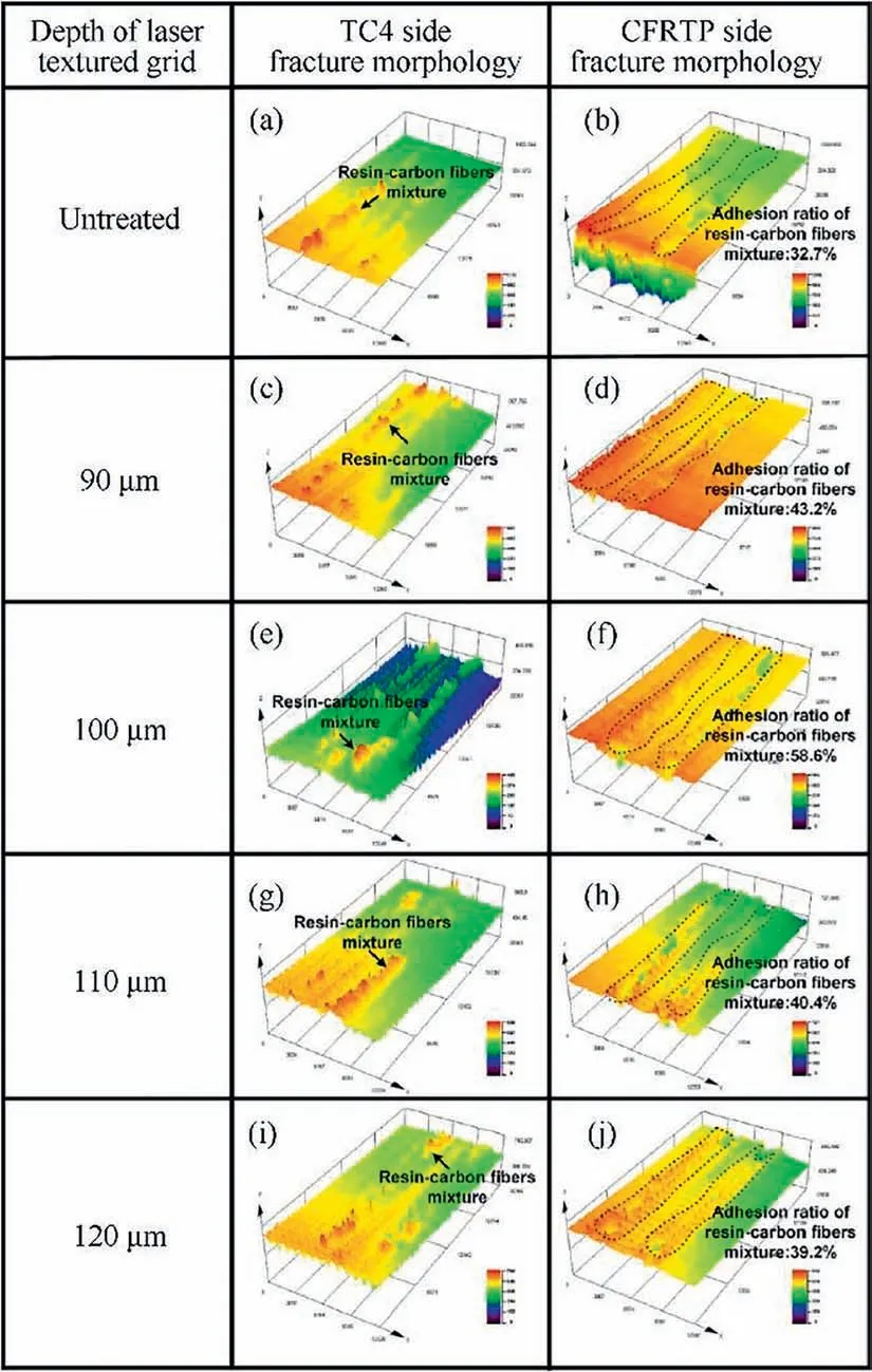
Fig.10 Fracture surface optical 3D morphology of TC4 sides and CFRTP sides under various TC4 sheet surface with laser texture grid depths.
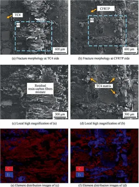
Fig. 11 SEM fracture surface morphology and element distribution of CFRTP/TC4 laser joining joint under the condition of TC4 substrate with 100 μm-depth texture grid.
Fig. 11 presents the SEM morphology of typical fracture surface under the condition of laser textured TC4 surface with 100 μm-depth grid. Some molten CFRTP was found to be filled into the texture grid, while a large number of residual resin-carbon fibers mixture remained on the local fracture surface of TC4 as shown in Fig. 11(c) and (e). This phenomenon revealed that the failure occurred on the laser texture space surface and interior of CFRTP during the tensile-shear test,which suggested that fracture mode of laser joining joints under the case of laser textured TC4 surface was mixed failure including interface failure and cohesive failure.44It was worth noting that the TC4 matrices with grid morphology were exfoliated and adhered at the local fracture surface of CTRTP substrate as exhibited in Fig. 11(d) and (f), which was different from our previous studies.29This result indicated that the molten resin embedded into the inside of laser textured TC4,local TC4 matrix particles in texture grid were stripped from the substrate under the action of tensile-shear force. Therefore,the laser joining strength enhanced predominantly between TC4 and CFRTP substrates after laser textured TC4 substrate surface.
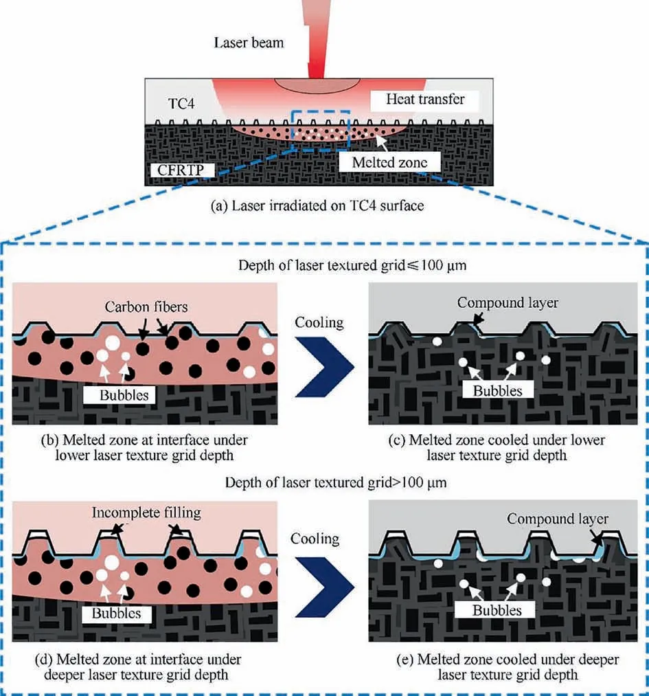
Fig. 12 Schematic diagram of laser joining process.
3.4. Joining mechanism
Fig.12 presents the schematic of laser joining CFRTP to laser textured TC4.Laser irradiated the TC4 sheet surface,the heat conducted from the TC4 surface to the texture grid interface.Two molten pools formed including molten pool of TC4 substrate sheet and melted zone of CFRTP because the melting point of TC4 and melting range of CFRTP were reached at TC4 sheet surface and contact interface, respectively. The CFRTP near the interface melted, local temperature exceeded the gasification point of resin causing tiny bubbles generated inside the melted zone of CFRTP as shown in Fig. 12(a).The molten CFRTP wetted and spread on the laser textured TC4 surface,and filled into the texture grid under the cylinder pressure. The bubbles with high pressure generated by resin gasification could also further promote the interlocking of molten CFRTP to texture grid of TC4 substrate during bubbles expansion and flow.45The melted CFRTP could completely fill into the texture grid in the case of lower texture grid depth. However, the incomplete filling occurred at the joining interface owing to relative deeper texture grid as exhibited in Fig.12(b)and(d).Upon cooling,the mechanical interlocking retained at the joining interface and some residual tiny bubbles remained at the CFRTP substrate as presented in Fig. 12(c) and (e). C element diffused towards the contacted TC4 surface, a compound layer dominated by CTi0.42V1.58phase at the interface because carburization of C element with active Ti element and other elements under high interfacial temperature as exhibited in Fig.12(b)and(d).Chemical bonding was thus confirmed. As for in-depth analysis of the chemically bonded phase at the interface, present work is under way.
4. Conclusions
(1) Grids in various depths were textured on TC4 sheets by nanosecond laser system. Tight laser joining joints of CFRTP to laser textured TC4 sheets were observed and no defects were detected owing to optimized joining process parameters. Both mechanical interlocking and chemical bonding between molten CFRTP substate and TC4 sheet occurred at joining regions.
(2) The wettability of molten CFRTP substrate on TC4 surface was significantly improved after laser textured TC4 surface, contact angle decreased from 111.2° to approximately 60°. The minimum contact angle was 56.3o in the case of texture grid depth of 100 μm.With the depth of texture grid sequentially increased, the contact angle increased gradually increased and the phenomenon of melted resin could not completely fill into texture grid of TC4 surface appeared.
(3) The shear force increased by approximately 156% after laser textured TC4 surface. With the increase of texture grid depth, the tensile-shear force first increased and then decreased, which was corresponded with the adhesion ratio of resin-carbon fibers mixture at the fracture surface. The maximal shear force was 2621 N when the texture grid depth was 100 μm, and the resin-carbon fibers mixture adhesion ratio also reached the maximum of 58.6% in this case.
(4) The failure mode of joining joint was mixed failure including interface failure and cohesive failure. TC4 matrixes were stripped from TC4 substrate and adhered at the fracture surface of CFRTP owing to relatively high interfacial joining strength after later textured TC4 surface.
Declaration of Competing Interest
The authors declare that they have no known competing financial interests or personal relationships that could have appeared to influence the work reported in this paper.
Acknowledgement
This research was financially supported by National Natural Science Foundation of China (No. 51875129).
 CHINESE JOURNAL OF AERONAUTICS2021年5期
- CHINESE JOURNAL OF AERONAUTICS的其它文章
- Ferrofluid moving thin films for active flow control
- Preliminary study on heat flux measurement data of TT-0 flight test
- An analysis and enhanced proposal of atmospheric boundary layer wind modelling techniques for automation of air traffic management
- Jet sweeping angle control by fluidic oscillators with master-slave designs
- Hot deformation behavior and microstructure evolution of the laser solid formed TC4 titanium alloy
- Electrochemical trepanning with an auxiliary electrode
