BN/SiBCN light-leakage-proof coatings of silica optical fiber for long term sensors at high temperatures
Xin’gng LUAN, Xinming XU, Rong YU, Qiqi ZHANG, Sm ZHANG,Lifei CHENG
a Science and Technology on Thermo Structural Composite Materials Laboratory, Northwestern Polytechnical University,Xi’an 710072, China
b Faculty of Materials and Energy, Southwest University, Chong Qing 400715, China
KEYWORDS BN/SiBCN double coating;High temperature;Optical fiber;Sensor;Silica
Abstract SiBCN and BN/SiBCN light-leakage-proof coatings were prepared on silica optical fibers for sensing applications at high temperatures.Scanning electron microscopy was used to characterize the surface morphology and microstructure of the coated fiber. Mechanical and optical properties of the coated fiber were characterized by Raman, optical and tensile tests. Compared with the original fiber,the tensile strength of SiBCN and BN/SiBCN coated fiber show an increase of about 60%and 90%at room temperature, respectively. In addition, the tensile strength of BN/SiBCN coated silica optical fiber was increased by about 42%at 700°C.It has been found that the improvement of the strength of BN/SiBCN coated silica optical fiber is related to the healing of defects and residual compressive stress in fibers. From the light transmittance performance of the coated fiber,it was found that BN/SiBCN double coating could be an ideal total reflection solution to protect silica optical fiber from light leakage during high temperature sensing operation.
1. Introduction
Optical fiber grating sensors have the advantages of high accuracy,small size,light weight,wavelength division multiplexing,long service life, high reliability, corrosion resistance, long transmission distance.1,2They can measure various kinds of parameters such as stress,strain,temperature,force and acceleration.Thus,optical fiber grating sensors have broad application prospect in the field of aviation structural health monitoring.3-9However, defects, such as micro-cracks, still exists in optical fiber after they are prepared,which could lead to the decrease of their strength. Furthermore, when optical fiber gratings are used to monitor aviation structural health,they would serve at high temperature (might higher than 700°C)and probably with high H2O(g)partial pressure.Consequently,the degradation of optical fiber would be intensified.Thus,it is necessary to study the protection method of optical fiber at high temperature.
Normally, surface coating is one of the protective methods of silica optical fiber.10Polymer coatings, such as polymethyl acrylate and polyimide, are not suitable to be used above 300°C for their poor thermal stability and oxidation resistance.2Thus, metal and inorganic nonmetallic coatings are considered to be the ideal candidates to protect silica optical fiber at high temperature.
As early as 1989,Bnbel et al.11had investigated the reliability of mechanical properties of surface metallized optical fiber.Jiang et al.12used electroless nickel method to metallize the surface of silica optical fiber. The nickel-plated fiber with bright surface, good solderability and moderate interfacial strength was obtained.Moreover,the nickel-plated fiber could meet the plasticity requirements of application at high temperature (200-800°C). Sham et al.13investigated the effects of thickness and roughness of nickel coating on mechanical properties of nickel-plated optical fiber not only theoretically but also experimentally.However,the difference in thermal expansion coefficient and elastic modulus between metal coating and silica optical fiber could be pretty large, which could lead to high residual stress and crack of the coating. Additionally,metal coatings often exhibit poor resistance to chemical and electrochemical corrosion, which also means poor reliability in corrosive environments. Thus, inorganic nonmetallic might perform better service properties as protective coatings of silica optical fiber at high temperature.
Polymer-derived SiBCN ceramics (PDC SiBCN) have excellent high-temperature stability and oxidation resistance.14-18PDC SiBCN begin to oxidize at 1200°C and their oxidation products can effectively hinder the diffusion of H2O(g),which is beneficial to protect silica optical fiber at high temperature.However,the coefficient of thermal expansion of silica optical fiber and PDC SiBCN is 0.56×10⁻⁶/K19and 3.5×10⁻⁶/K20,respectively.Considering the pyrolysis temperature of SiBCN precursor can reach to hundreds or even more than a thousand degrees Celsius, the thermal residual stress in the coating could be pretty large and the coating might crack or even peeling off. Thus, a transition layer with a coefficient of thermal expansion in between needs to be prepared between silica optical fiber and PDC SiBCN coating. BN have the advantages of excellent high temperature stability, thermal shock resistance, oxidation resistance up to 800°C and low density.21-23And the coefficient of thermal expansion of BN is 2.3×10⁻⁶/K, which is lower than that of PDC SiBCN but higher than silica optical fiber. Besides, in our previous work,it has been proven that BN can be a protective coating of sapphire optical fiber for healing the defects.24Thus,BN have the potential to be used as a transition layer between silica optical fiber and PDC SiBCN.
In this work, PDC SiBCN and BN/SiBCN coatings were prepared on silica optical fiber. Surface morphology,microstructures, mechanical properties and optical properties of the coating were characterized by scanning electron microscopy, Raman, optical and tensile tests, respectively.
2. Experimental
2.1. Materials
The diameter of silica optical fiber used in the experimental is 125 μm and its physical properties are shown in Table 1.SiBCN precursor (polyborosilazane, PSNB) was produced by the Beijing Institute of Chemistry, Chinese Academy of Sciences. Analytically pure Tetrahydrofuran (THF) from Tianjin Fuyu Fine Chemical Co., Ltd was used as solvent.Argon with a purity of 99.99 %, hydrogen with a purity of 99.99 % was produced by Sichuan Messer Gas Products Co., Ltd. Boron chloride with a purity of 99.9 %, ammonia with a purity of 99.99%was produced by Beijing Multi Technology Co., Ltd.
2.2. Coating preparation
The protection cladding of silica optical fiber was removed by mechanical methods.Then,the fibers were cleaned in an ultrasonic bath for 15 min with acetone, alcohol and deionized water sequentially.
The process diagram exhibiting the preparation method of both BN/SiBCN and SiBCN coating of silica optical fiber is shown in Fig. 1. BN coating was prepared on the fiber via Chemical vapor deposition (CVD) process.24After that,SiBCN coating was prepared by polymer derived ceramics method. Firstly, a precursor solution was prepared by using THF as solvent. The solution was prepared at a mass ratio of PSNB to THF of 1:2 and 1:3, respectively. The solution was mixed for about 15 min using an ultrasonic cleaner. Secondly, BN coated silica optical fiber was immersed in the prepared precursor for 1 h. Thirdly, the samples were cured at 120°C in air for 2 h. Finally, the samples were pyrolyzed at 700°C in Ar for 2 h.
2.3. Characterization
Tensile test was performed on an electronic universal testing machine (Instron-3345, USA) loaded with aluminum rings.The gauge lengths of the samples are 50 mm at room temperature and 160 mm at 700°C, respectively. The loading rate of tensile test is 0.1 mm/min. Raman spectra of the prepared coating was obtained by a Raman spectroscopy (Renishaw Raman, UK), equipped with a He-Ne laser (I=532 nm).Thickness and morphology of the coating were examined using scanning electron microscope (SEM, Hitachi S-4700, Japan).Chemical composition of the coating was performed by energy-dispersive spectrometer (EDS, Genesis, UK). Optical transmittance of coated fiber was tested with an optical fiber test pen (SG-A7R). The light source is a semiconductor laser with the wavelength of 650 nm.
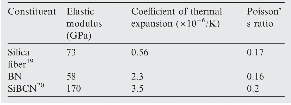
Table 1 Physical properties of the components in the coated silica optical fiber system.
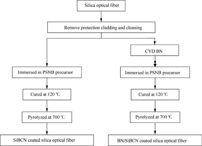
Fig. 1 Preparation process of BN/SiBCN and SiBCN coating of silica optical fiber.
3. Results and discussion
3.1. Coating design
In this work, COMSOL software was used to simulate the residual stress distribution of rod-like materials from pyrolysis temperature (700°C) to room temperature using the axisymmetric model. The grid is in triangle form and the thickness of PDC SiBCN (marked as t) are 1, 3, 5, 7, 9, 10, 11, 13 μm,respectively. In addition, the thickness of BN (marked as s)is fixed at 1 μm in BN/SiBCN coated silica optical fiber. The calculation model for SiBCN and BN/SiBCN coated silica optical fiber are shown in Fig.2(a)and(b),respectively.Physical properties of the components are shown in Table 1, and the calculated results are shown in Fig. 3.
It could be found in Fig. 3(a) and (b) that the axial and radial stress changes sharply on the interface between SiBCN coating and silica optical fiber, which is harmful for the mechanical properties of the sample. Fig. 3(c) and (d) show the axial and radial residual stress of BN/SiBCN coated silica optical fiber with different t.The axial and radial stress show a step change,which indicates that BN acts as a transition layer alleviating the thermal residual stress caused by thermal mismatch.Additionally,as t increases,the axial compressive stress of silica optical fiber and BN would gradually increase and the axial tensile stress of SiBCN would decrease. Meanwhile, as t increases, the radial compressive stress of silica optical fiber,BN and SiBCN coating would increase. Besides, when t exceeds 7 μm, the change in axial and radial residual stress would be negligible.
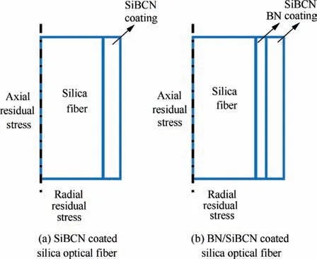
Fig. 2 Calculation model for coated silica optical fibers.
3.2. Microstructure
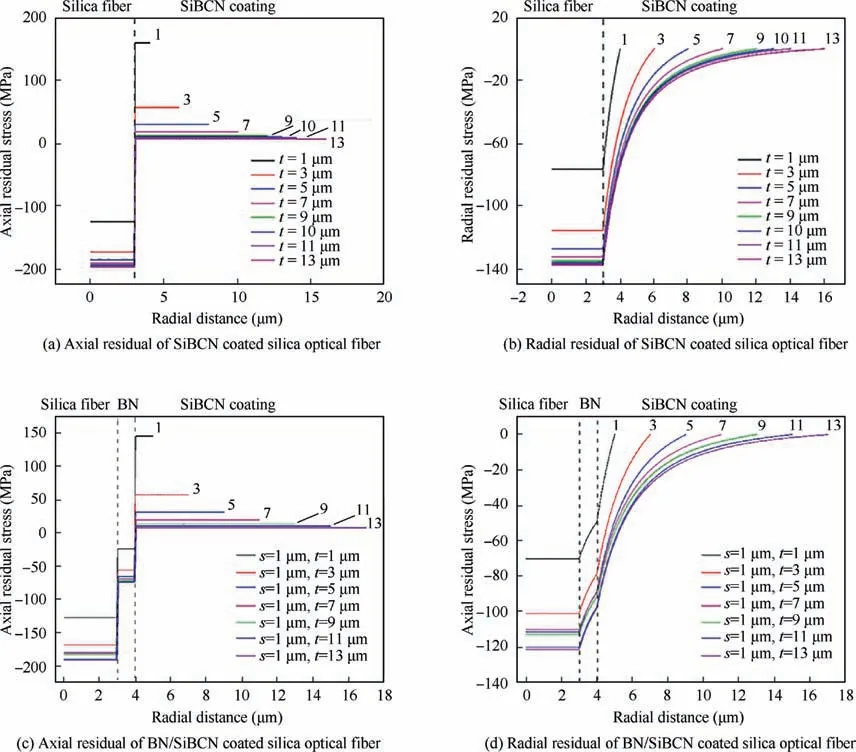
Fig. 3 Distributions of residual stress for silica optical fiber with different t.
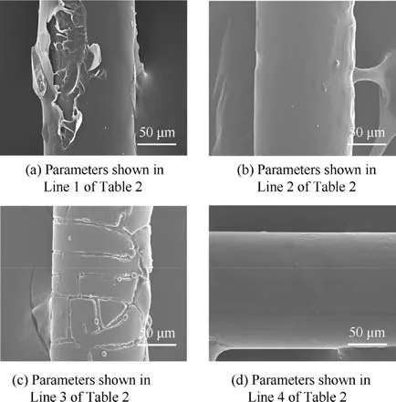
Fig. 4 Surface morphology of PDC SiBCN coated silica optical fiber prepared through different methods.
Fig. 4 shows the surface morphology of PDC SiBCN coated silica optical fiber. The parameters for preparing PDC SiBCN coating are shown in Table 2. It could be found in Fig. 4(a)and (b) that the SiBCN coating would be flatter and denser when the mass ratio of PSNB to THF is 1:2.This phenomenon is related to the volatilization of THF during curing process,which would be more drastic when the THF concentration increases. Therefore, when the mass ratio of PSNB to THF is 1:3,more cracks and pores would be generated in the coating during curing process. As shown in Fig. 4(b) and (c), the surface of silica optical fiber prepared with three cycles of immersing-curing process is flatter than that with five cycles.As exhibited in Fig. 3(b) and (d), the thermal residual stress in PDC SiBCN coating would increase as t rises. Therefore,the coating tends to crack when the immersing-curing process is carried out too much times. Additionally, it could also be found in Fig. 4(b) and (d) that the coating would be flatter as the heating rate of pyrolysis is decreases.Based on our previous work related to the pyrolysis procedure of PSNB and its main effect factor,25,26this phenomenon is related to the volatilization of small-molecule gases such as NH3, H2, H2O,CH2and CO2. When the heating rate decreases, the pyrolysis of PSNB would be slower and more sufficient. Therefore, the number of defects caused by the discharge of small-molecule gases from the coating would decrease, which is beneficial to the densification and integrity of the coating.Thus,the coating would become much thinner and flatter when the heating rate of pyrolysis decreases.Hence,the parameters shown in the last line of Table 2 are selected to prepare SiBCN and BN/SiBCN coating in this work.
It can be found in Table 3 that PDC SiBCN coating has been obtained although the oxygen content of the coating is 29.91 %. The elemental composition shown in Table 3 corresponds to the sample shown in Fig. 2(d). It could be found in Table 2 that t is 0.5 μm for this sample. Therefore, the EDS result might contain the background signal of silica optical fiber, which further result in the high oxygen content.Moreover, it should not be ignored that EDS is imprecise for the quantitative analysis of light elements. However, it is still undeniable that the SiBCN coating obtained in this work still contains oxygen since the curing and pyrolysis process are carried out in air. The curing and pyrolysis process in air can be regarded as a pre-oxidation step, which can avoid the volume expansion and decrease of the mechanical properties of the coating during high-temperature mechanical test.

Table 2 Comparison of parameters for preparing PDC SiBCN coatings.

Table 3 Elemental composition of PDC SiBCN coating.
Surface and cross-section morphologies of BN/SiBCN coated silica optical fiber are shown in Fig.5.It could be found in Fig.5(a)that the coating is flat when t is 0.5 μm as shown in Fig. 5(b), just with a few defects on the surface. However,when t is 2 and 2.5 μm as shown in Fig. 5(d)and(f),the coating would be porous and rough(see Fig.5(c)and(e)).The reason for this phenomenon is that the small-molecule gases generated during the pyrolysis process is hard to diffuse out when the coating is too thick.
3.3. Mechanical properties
Fig. 6 shows the Raman spectra of PDC SiBCN coated silica optical fiber. Two peaks at 1345 cm-1and 1579 cm-1could be found on the curve.The former has a negative displacement(5 cm-1) with the reference value of the G peak of carbon(1350 cm-1), while the latter has almost no deviation from the reference value of the D peak of carbon (1580 cm-1).27This phenomenon indicates that PDC SiBCN coating is subjected to residual tensile stress, which is consistent with the results of COMSOL finite element analysis discussed in Fig.3.
It could be found in Table 4 that both tensile strength and elastic modulus of SiBCN coated silica optical fiber increases initially and then decreases as t increases. The highest tensile strength and elastic modulus of 258±3.7 MPa and 55±2.0 GPa are obtained when t is 0.5 μm, respectively.
t could be found in Fig.7 that the defects of SiBCN coating could be the crack source (see the white circles). However, the fracture morphology of the fibers with different t could be quite different.It could be found in Fig.7(a)that a large piece of coating debris adheres to the fracture surface,indicating the debonding between silica optical fiber and PDC SiBCN coating. This mechanism can consume energy and alleviate the stress concentration. Besides, the debonding between silica optical fiber and PDC SiBCN coating could also be found in Fig. 7(b), which could relieve the stress concentration at the crack tip. Therefore, the improvement reasons for tensile strength of BN/SiBCN coated silica optical fiber includes the healing of defects (see Fig. 4) and residual compressive stress in the fiber (see Fig. 3).
Raman spectra of BN/SiBCN coated silica optical fiber is shown in Fig.8.Two peaks at 1342 cm-1and 1580 cm-1could be found on the curve shown in Fig. 8. The former showed a negative displacement(8 cm-1)with the reference value of carbon(1350 cm-1),which proved that the SiBCN coating is subjected to residual compressive stress. This phenomenon is consistent with the finite element simulation discussed in Fig. 3.
It could be found in Fig. 9(a) that the tensile strength of BN/SiBCN coated silica optical fiber increases initially and then decreases as t rises. The highest tensile strength of 308±18.5 MPa is obtained when t is 1.3 μm. Besides, it could be found in Fig.9(b)that BN/SiBCN coated silica optical fiber exhibits a linear deformation behavior, which is benefit to its application as a strain sensor.Additionally,the fracture strain of BN/SiBCN coated silica optical fiber is about two times higher than that of the original fiber.
Fig. 10 shows the fracture morphology of the original and BN/SiBCN coated silica optical fiber with different t. A fracture mirror could be found on the fracture surface of the original silica optical fiber.However,the fracture mirror could not be found in Fig. 10(b) and the fracture mirror in Fig. 10(c) is much smaller than that in Fig.10(a).According to the conventional fracture mirror method,the strength of the fiber is inversely proportional to the size of the fracture mirror.28-30Thus,when t is 1.3 and 2 μm,the tensile strength of the coated fiber is higher than that of the original fiber. When t is 2.5 μm, the defects of the coating could become crack sources (see Fig. 10(d)). Therefore, the ideal value of t is 2.5 μm, which is consistent with the conclusion drawn in Fig. 9(a). Besides, it could be found in Fig.10(b)that a large piece of coating debris exists on the fracture surface, indicating the debonding between silica optical fiber and coating. Thus, the improvement reason for the strength of BN/SiBCN coated silica optical fiber at room temperature can also be contributed to the healing of defects (see Fig. 5) and residual compressive stress in fiber (see Fig. 3(c) and (d)).
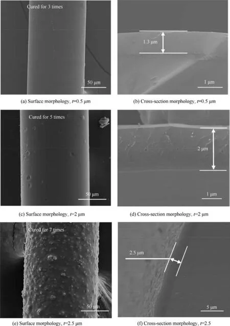
Fig. 5 Surface and cross-section morphology of BN/SiBCN coated silica optical fiber with different t.
As shown in Fig.11(a),the highest tensile strength and elastic modulus of 185±8.32 MPa and 35±1.67 GPa are achieved when t is 1.3 μm. However, when SiBCN coating is thicker than 2 μm, the tensile strength would decrease. Moreover, it could be found in Fig. 11(a) that the elastic modulus of the coated fiber is about two times higher than that of the original fiber. The explanation for this phenomenon is that SiBCN coating limits the deformation of the silica optical fiber. And this also illustrates that the interface bonding is tight at 700°C.According to Table 1,silica optical fiber would be subjected to axial tensile stress at 700°C,which would lead to a decrease in the mechanical properties of the fiber. Therefore, the mechanical property of coated fiber at 700°C are much lower than that at room temperature. Fig. 11(b) shows the tensile stress-strain curves of the original and BN/SiBCN coated silica optical fibers at 700°C.Interestingly,an inflection point could be found on the stress-strain curve (see the black circle in Fig. 11(b)). On the right side of the point, the slope of the curve increases significantly, which means that the deformation capacity of the sample decreases. Therefore, this point represents the boundary where the crack begins to expand in silica optical fiber.Moreover,the stress corresponding to this point is the in-situ strength of silica optical fiber at 700°C. Although the fiber would be subjected to axial tensile stress at 700°C, the strength of the fiber is still much higher than that of the original fiber, which indicates that the defects on the fiber surface have been repaired by the BN/SiBCN coating.
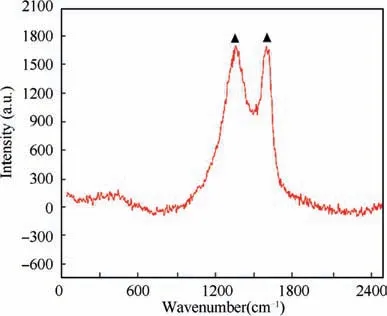
Fig.6 Raman spectra of PDC SiBCN coated silica optical fiber.

Table 4 Elastic modulus and tensile strength of PDC SiBCN coated silica optical fiber with different t at room temperature.
It could be found in Fig. 12 that the fracture mirror would become larger when SiBCN coating is thicker. As shown in Fig.12(a),the fracture surface of the original fiber is flat.However, the fracture surface of BN/SiBCN coated silica optical fiber is uneven, and it could be found in Fig. 12(b), (c) and(d) that the cracks extend from the coating into silica optical fiber (see the white dashed rectangles). These regions might be the area where the cracks extend from the coating into the fiber. This phenomenon indicates that the failure of BN/SiBCN coating precedes the destruction of silica optical fiber and the interface bonding is tight.
3.4. Optics properties
The light transmittance of the coated fiber was investigated using the SG Visual Fault Locator. The fiber was placed in the optical interface, and the semiconductor laser emitted an optical signal with the wavelength of 650 nm and the pulse frequency of 2-3 Hz, which was expanded by a beam expander and projected onto the silica optical fiber.31

Fig. 7 Fracture morphology of PDC SiBCN coated silica optical fiber with different t at room temperature.
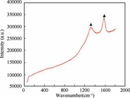
Fig. 8 Raman spectra of BN/SiBCN coated silica optical fiber.
As shown in Fig.13(a),the laser spreads out from the original silica optical fiber which indicates that the fiber has poor transmittance. However, it could be found in Fig. 13(b) and(c) that the laser can go through SiBCN and BN/SiBCN coated silica optical fiber successfully and stably without light leakage. This indicates that both CVD BN and PDC SiBCN could be an ideal total reflection coating.
However,an ideal protective light-leakage-proof coating of silica optical fiber for their application as strain sensors at high temperature should not only have favorable optics properties but also have high strength, high elastic modulus, oxidation resistance,linear deformation behavior and thermal expansion match with the fiber.Thus,according to the discussion above,BN/SiCBN coating could be the qualified total reflection coating of silica optical fiber aims to achieve their long-term sensor applications at high temperature.
4. Conclusions
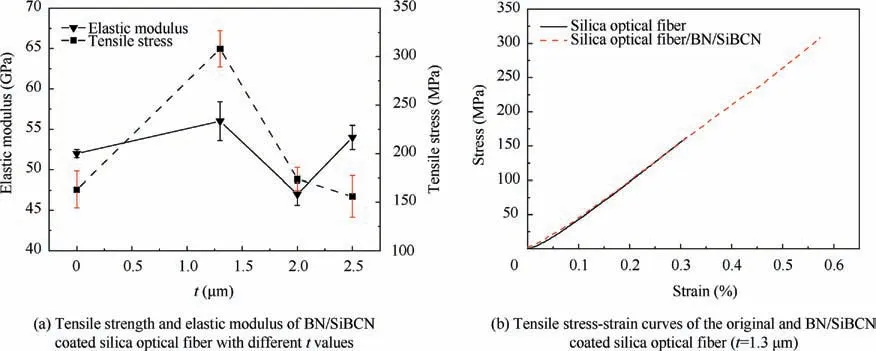
Fig. 9 Mechanical properties of original and BN/SiBCN coated silica optical fibers with different t at room temperature.
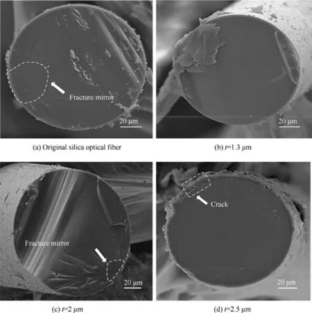
Fig. 10 Fracture morphology of original and BN/SiBCN coated silica optical fiber with different t at room temperature.
In this work,SiBCN and BN/SiCBN light-leakage-proof coating of silica optical fibers were prepared.It has been found that the suitable coating thickness of SiBCN and BN/SiCBN for defect-heal of silica optical fibers was 0.5 and 1.3 μm, respectively. The tensile strength of BN/SiBCN coated silica optical fiber is much higher than that of SiBCN coated silica optical fiber. The improvement of the strength of BN/SiBCN coated silica optical fiber can explained by the healing of defects and residual compressive stress in fibers.BN/SiCBN coated silica optical fibers also showed favorable high temperature mechanical properties.Both SiBCN and BN/SiCBN coated silica optical fibers has good light transmission property. Based on the conclusions above, BN/SiBCN coating is selected to be the qualified total reflection coating which aims to achieve long-term sensor applications at high temperature.
Declaration of Competing Interest
The authors declare that they have no known competing financial interests or personal relationships that could have appeared to influence the work reported in this paper.
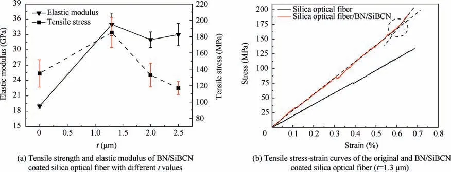
Fig. 11 Mechanical properties of original and BN/SiBCN coated silica optical fibers with different t at 700°C.
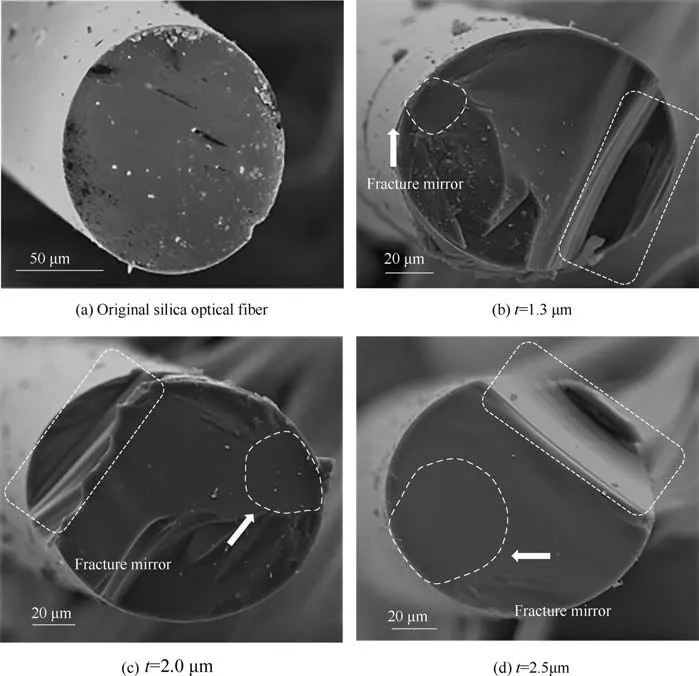
Fig. 12 Fracture morphology of the original and BN/SiBCN coated silica optical fiber with different t at 700°C.

Fig. 13 Transmittance analysis of silica optical fibers.
Acknowledgements
This study was co-supported by the National Natural Science Foundation of China (No. 91960105, 91860140), the National Basic Research Program of China(973 Program), the Open Fund of the State Key Laboratory on Integrated Optoelectronics, China (No. IOSKL2018KF05) and the Fundamental Research Funds for the Central Universities (No.SWU118105).
 CHINESE JOURNAL OF AERONAUTICS2021年5期
- CHINESE JOURNAL OF AERONAUTICS的其它文章
- Ferrofluid moving thin films for active flow control
- Preliminary study on heat flux measurement data of TT-0 flight test
- An analysis and enhanced proposal of atmospheric boundary layer wind modelling techniques for automation of air traffic management
- Jet sweeping angle control by fluidic oscillators with master-slave designs
- Hot deformation behavior and microstructure evolution of the laser solid formed TC4 titanium alloy
- Electrochemical trepanning with an auxiliary electrode
