Confinement characteristic of primary electrons with the variation of channel width in the discharge chamber of annular ion thruster
Chang LU, Guangqing XIA,*, Bin SUN, Yajie HAN
a State Key Laboratory of Structural Analysis for Industrial Equipment, Dalian University of Technology, Dalian 116024, China
b Key Laboratory of Advanced Technology for Aerospace Vehicles of Liaoning Province, Dalian University of Technology,Dalian 116024, China
KEYWORDS Annular ion thruster;Average confinement length;Electric propulsion;Ion thruster;Primary electrons
Abstract In this paper, the confinement characteristic of primary electrons in the nonaxisymmetric discharge chamber of annular ion thruster is investigated by a three-dimensional(3D) non-self-consistent particle tracking model with Monte Carlo Collision (MCC) method.The results show that: The density of primary electrons upstream of ion optics on cathode axis is about 5-50 times higher than that of the other side, which means that the density of primary electrons is obviously non-axisymmetric.The channel width has a significant effect on the average density and uniformity of primary electrons. The average density can be increased by nearly 1.5 times under the appropriate channel width, meanwhile, the variance of density distribution can be reduced by more than 2 times. This is because that increasing the channel width can improve the average confinement length of primary electrons greatly. Furthermore, there is an infection point in the increase of primary electron average confinement length with the channel width,which caused by the significant change of magnetic field structure. Under the case after the inflection point, primary electron mainly(more than 50%)moves to the channel center,which makes the average confinement length of primary electrons and their number in the discharge chamber increase largely.
1. Introduction
Presently, electric thruster has become the main thrust device for deep space missions. Ring-cusp ion thruster1is one of the most popular electric thrusters with high efficiency and specific impulse.2-4However, the thrust and power of most commonused Ring-cusp ion thruster, like NSTAR ion thruster5-7and LIPS-300 ion thruster,8are still not enough to support the next deep space exploration mission.9Higher power ion thruster is in a great need. The thrust and power of Ring-cusp ion thruster are basically determined by its outlet area.10-12However,due to the difficulty in manufacturing large-scale ion optics,it is hard to greatly improve the diameter of conventional Ring-cusp ion thruster. Meanwhile, the input power tends to decrease with the increase of the thruster‘s diameter.9Up to now,these two problems are still very critical for the improvement of higher power Ring-cusp ion thruster.
In order to deal with the above problems, Patterson et al.9,13-15proposed the concept of annular ion thruster in 2011.As shown in Fig.1,in annular ion thrusters,the annular structure with double anodes is adopted.9,15Hence,the span of its ion optics is decreased largely,thus greatly reducing the difficulties in manufacturing large-scale ion optics.Moreover,the area of anode is nearly doubled, which significantly increases the limit of input power. Therefore, by changing the structure of discharge chamber,annular ion thruster has the potential to break through the thrust and power limit of conventional Ring-cusp ion thruster.
However, in Patterson‘s design, the cathode of annular ion thruster is set to be biased on one side of the discharge chamber, which makes its discharge is naturally uneven. The nonuniformity will significantly increase the discharge loss and reduce the service life of the thruster.16In 2015,Lanzhou Institute of Physics also launched the development of a 50 cm diameter annular ion thruster,and carried out its performance test in 2017.17The uneven discharge was observed in their experiments. On the other hand, some experiments14,15have shown that the annular discharge chamber can have a uniform discharge process, and the straightness of beam ions can be good as well. However, these researches mainly focus on the observation of the annular ion thruster performance. More reasonable explanations are still needed to further improve the performance of annular ion thruster.
In a Ring-cusp ion thruster,primary electrons are the main contributor of ionization collision, and their characteristics have essential influence on the whole discharge process. The distribution and energy of primary electrons can significantly affect the distribution and density of plasma, and then affect the discharge loss, thrust and specific impulse, et al. Due to the importance of primary electrons on the discharge process,in this paper, the confinement characteristics of primary electrons in the discharge chamber of annular ion thruster are studied by simulations for the first time. In order to clarify the effects of the non-axisymmetric structure of annular ion thruster on primary electrons, a three-dimensional (3D) nonself-consistent particle tracking model with Monte Carlo Collision (MCC) method is established and utilized. Considering that the diameter of the discharge chamber can significantly affect the volume-area ratio of the discharge chamber, and thus affect the average confinement length of primary electrons, the confinement characteristics of primary electrons under different channel widths are also compared.In Section 2,the 3D non-self-consistent particle tracking model with MCC method is presented.In Section 3 and Section 4,the simulation results and the analysis are provided. Finally, the conclusions will be given in Section 5.
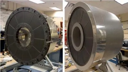
Fig. 1 Annular ion thruster developed by NASA Green Research Center.
2. Computational model
The 3D non-self-consistent particle tracking model with MCC method contains two sub-models,the magnetic field model and the primary electron model.The magnetic field model is implemented through the MAXWELL 3D software.18The primary electron model is part of a 3D discharge chamber model for conventional Ring-cusp ion thrusters developed by Lu et al.19-23. These two models are described below.
2.1. Magnetic field model
Because the induced magnetic field produced by discharge is much smaller than the static magnetic field of permanent magnet,only the static magnetic field of permanent magnet is considered in this model. The static magnetic field can be described by the following equations,

together with the following boundary conditions,

where A is the magnetic vector potential,n is the normal vector of the boundary,μis the magnetic permeability, J is the equivalent current, and can be expressed as,

where Hcis the coercive force.
After A is obtained,the magnetic induction intensity B can be obtained by Eq. (5),

B is the final parameter needed to input onto the primary electron model.In MAXWELL 3D software,an adaptive grid solver is used, and the convergence results of B with error less than 0.6% can be obtained.24
2.2. Primary electron model
In the 3D non-self-consistent particle tracking model with MCC method, the detailed information of the flow field is obtained by directly tracking the motion process of a large number of simulated particles. When the number of particles is enough, this model can approach the real physical process.In this model, particle tracking method is used to track the motion and position of primary electrons,while MCC method is used to simulate the collision process.
2.2.1. Particle tracking method
In particle tracking method,the initial state of particles should be determined according to the input parameters. In this model, the initial state of primary electrons includes the emitted number, initial position and initial velocity. The number and initial position are determined by the emission current of the cathode and the position of the cathode top, while the initial velocity is determined by the initial energy of the primary electron.
As shown in Fig.2,the cathode emission current Ierefers to the current composed of primary electrons emitted from the emitter at the cathode top,while the discharge current Idrefers to the current composed of charged particles received from the anode wall,and the beam current Ibrefers to the current composed of ions drawn from the grid.In an ideal ion thruster discharge chamber, all the ions are led out by the grid, while the electrons (including the primary electrons and the secondary electrons produced by the ionization of neutral atoms) are all absorbed by the anode. Therefore, the discharge current Idis mainly composed of Ieand the secondary electron current Ise, i.e. Id=Ie+Ise. Because the number of secondary electrons is equal to the number of ions, Id=Ie+Ib.
Therefore,the cathode emission current Iecan be calculated from the discharge current Idand beam current Ib25:

The initial position of primary electron is located at the cathode emitter, which is evenly distributed. In addition, the plasma sheath at each boundary of the discharge chamber is ignored. The primary electrons are set to be emitted from the plasma sheath edge of the cathode. Therefore, the initial velocity of primary electron is the velocity accelerated by the sheath potential. Since the sheath potential drop (about 30 V) is much larger than the thermal kinetic energy (2 eV)of primary electron, the initial velocity of primary electron in the axial direction(Z direction)is defined as the velocity accelerated by the sheath potential, while the initial velocity in the other two directions (X and Y directions) conforms to the Maxwell distribution25:
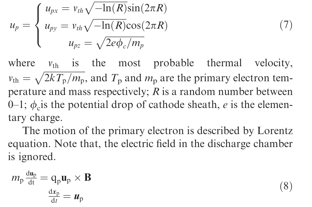
where qpis the primary electron charge; xpis the position of one primary electron.
Eq. (8) is solved by Boris leapfrog algorithm26. The basic idea of leapfrog algorithm is using finite difference to solve Eq.(8),but the position update is required to be half time step slower than the velocity update,as shown in Fig.3.In Fig.3,n means the nth iteration.
As shown in Fig. 4, at the node H, the density allocated from the simulated primary electron at point P is obtained by Eq. (9),

where ρpHthe density at the node H, VHis the volume of the shadow area in Fig. 4, V is the volume of the whole mesh. In Fig.4,i,j and k mean the ith node at x-axis,the jth node at yaxis, and the kth node at z-axis, respectively.
Finally, if one primary electron collides with the cathode and screen grid, they will be specular reflected. If it collides with the anode, it will be absorbed. In addition, if the energy of one primary electron is less than the threshold of ionization collision, it will be deleted from the simulation domain.
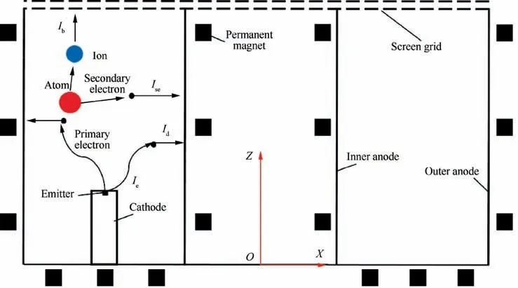
Fig. 2 Schematic diagram of ideal current relationship in discharge chamber of an annular ion thruster.
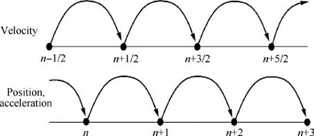
Fig. 3 Sketch of leapfrog algorithm.
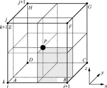
Fig. 4 Diagram of volume-weighted method.
2.2.2. MCC method
In MCC method,the collisions of primary electrons only contain four types: elasticity, excitation and ionization. The density and state of neutral atoms are assumed to be unchanged after all these collisions. If one primary electron collides with the atom elastically, its energy will remain unchanged, but its velocity direction will be reallocated; if one primary electron collides with the atom excitedly, it will lose 8.32 eV energy,and then the velocity direction will be also reallocated; if the ionization collision occurs, the energy of the primary electron and the newly generated secondary electron conforms to the following function27:
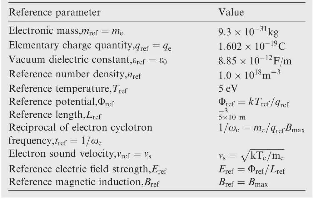
Table 1 Reference parameters and value.
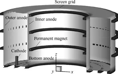
Fig. 5 Structure diagram of annular ion thruster.
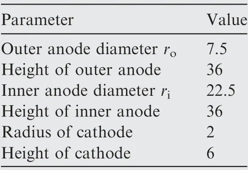
Table 2 Initial normalized geometric parameters.

where εsis the energy of the new secondary electron after ionization;εpis energy of primary electron after ionization;ϑ is an ionization parameters, ϑ≈8.7 eV; I is the ionization energy threshold; σiis the ionization impact cross section; the subscript s presents secondary electron.
Assuming that the energy of one primary electron before the ionization collision is Vp, the energy of the primary electron and the newly generated secondary electron after the ionization collision is27,

where R is a random number between 0-1.
The collision frequency of elastic collision, excitation collision and ionization collision can be calculated by the following equation,
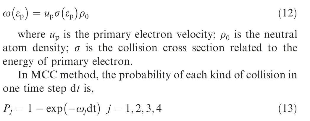
To judge whether the particle i collides, or which collision to choose if it collides,a random number RFis needed to compare with the probability of the j kind of collision,and then thecollision type is selected according to the comparison results.In order to improve the efficiency, the P-null Monte Carlo method developed by Vahedi28is used here. The basic idea of the P-null Monte Carlo method is calculating the maximum collision probability firstly,and then using the maximum probability to find out the particles that may collide.The maximum collision probability Pmaxcan be expressed as:

Table 3 Simulation case setting.
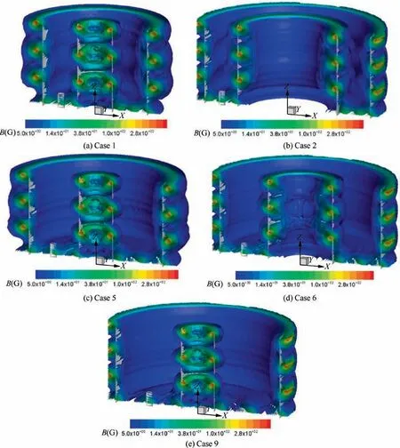
Fig. 6 Static magnetic field simulation results under different channel width.

where umaxis the maximum velocity of particles; ρmaxis the maximum density of atoms;σmaxis the maximum cross section,and ωmaxis the maximum collision frequency of particles.
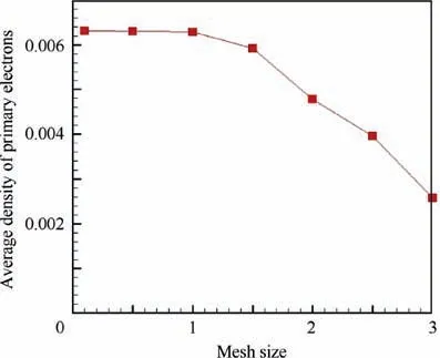
Fig. 7 Average density of primary in Case 1 under different mesh size.
Comparing Pmaxwith the first random number RF1, if RF1<Pmax, it is considered that two particles will collide.Then another random number RF2is generated. The ratio of the cross section of each collision to the total cross section is compared with RF2to determine which kind of collision occurs for the particle i.if RF2<ω1/ωtot(ωtotis the total collision frequency, ωtot=ω1+ω2+ω3), then the first type of collision occurs;if ω1/ωtot<RF2<(ω1+ω2)/ωtot,it is considered that the second collision type occurs; if (ω1+ω2)/ωtot<RF2<(ω1+ω2+ω3)/ωtot, it is considered that the third collision type occurs.
An important output parameter of the primary electron model is the average confinement length of primary electrons and the ionization rate G. The average confinement length L is given as
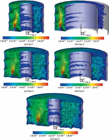
Fig. 8 Number density distribution of primary electron under different channel width.

Assuming that there are N simulated primary electrons with a weight w in one mesh with volume Vcell, the following equation can be obtained,

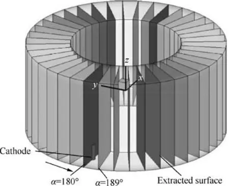
Fig. 9 Extracted surfaces.
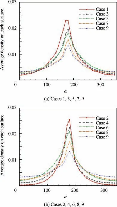
Fig. 10 Change of primary electron density along the circumferential direction.
3. Simulation setup
In our model,atoms are set to be a uniformly distributed background, and its number density is set to be 1.86×10¹⁹m-3,which is obtained according to the measurement in Ref.29.Discharge currents and beam currents are 11 A and 1 A,respectively. Hence, the cathode emission current is set to be 10 A. The plasma is assumed to be a quasi-neutral fluid with equal potential, so the electric field in the discharge chamber is ignored. The time step is set to less than one third of the reciprocal of the maximum electron cyclotron frequency in the whole simulation domain. The reference parameters and the reference values of these parameters are shown in Table 1.In the following content, except for the results marked with units, the rest of the simulation results are all normalized results.
Fig. 5 shows the schematic diagram of an annular ion thruster. It mainly consists of five parts: inner anode, outer anode, bottom anode, cathode, permanent magnet and grid.Table 2 shows its initial normalized geometric parameters. It can be seen that its channel width can be changed by adjusting the diameter of the inner anode and the outer anode.
In this paper, nine different diameters of the inner anode and the outer anode are selected to investigate the primary electron confinement characteristics under different channel widths. These 9 cases are shown in Table 3. The diameter of inner anode is defined as ri,while that of outer anode is defined as ro.In these cases,Case 1&Case 2,Case 3&Case 4,Case 5&Case 6,and Case 7&Case 8 have the same channel spacing,while Case 9 has the largest channel spacing. The static magnetic field distributions of Case 1, Case 2, Case 5, Case 6 and Case 9 are shown in Fig. 6. In all of these cases, the cross section size of permanent magnet remains unchanged.
In addition,we also divide the above cases into two groups:the first group is Cases 1,3,5,7,9,which is defined as the case reducing outer anode diameter;the second group is Cases 2,4,6, 8, 9, which is defined as the case increasing inner anode diameter.
4. Simulation results and analysis
In this section, the simulation results of primary electrons under different channel width are presented. Firstly, the 3D density distribution, tangential average density distribution and ionization rate distribution are given. The distribution characteristics of primary electron density and ionization rate are compared. Then, according to the average confinement length of primary electron and the structural characteristics of static magnetic field, the confinement characteristics of primary electron are analyzed.
4.1. Distribution characteristics of primary electron density and ionization rate
For Ring-cusp ion thruster,it is expected that the primary electron density and the ionization rate is high enough, and their distributions are required to be sufficiently uniform so that the uniformly distributed plasma can be obtained eventually.Therefore, here the distribution characteristics and average values of the primary electron density and ionization rate are mainly investigated.
Firstly,Fig.7 shows the average density of primary in Case 1 under different mesh size. It indicates the dependence of model accuracy on mesh size.According to Fig.7,the normalized mesh size 1 is selected. Therefore, the whole simulation domain has 82×82×36 meshes.
Fig. 8 presents the number density of primary electrons.Under all conditions, the density at the cathode side is much higher than that of the other side. In these cases, the density of primary electrons upstream of the ion optics on the cathode axis is about 5-50 times higher than that of the other side.Thismeans that the density of primary electrons is obviously nonaxisymmetric.

Table 4 Primary electron average density of each case.
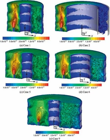
Fig. 11 Ionization rate under different channel width.
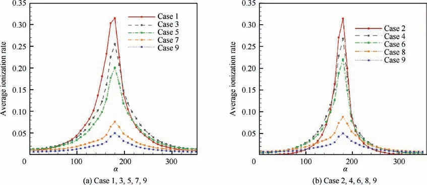
Fig. 12 Change of ionization rate along circumferential direction.

Table 5 The average ionization rate of each case.
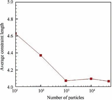
Fig. 13 Statistical average confinement length with number of particles in Case 1.
Another obvious feature is that with the decrease of the channel width, the difference between the number density on the cathode side and that on the other side increases.Furthermore, comparing Fig. 1 (a) with Fig. 1 (b), or Fig. 1 (c) with Fig. 1 (d), it can be found that, although the channel width is the same,the difference under the condition increasing inner anode diameter is larger.
To show this difference more clearly,we extract 40 surfaces in the discharge chamber and calculate the average density oneach surface. The extracted surfaces are shown in Fig. 9. The angle of the surface cutting the cathode around the thruster axis is set to be α=180°, where the counter-clockwise direction is set to the rotation direction.

Table 6 Average confinement length of each case.
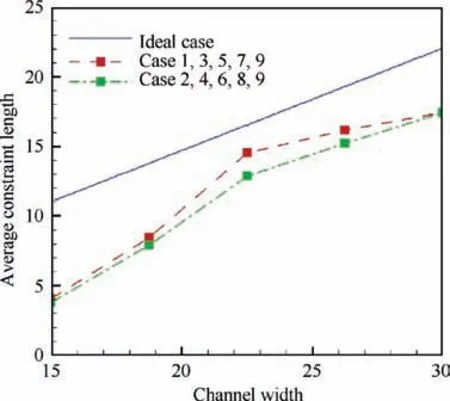
Fig. 14 Ideal and statistical average confinement length.
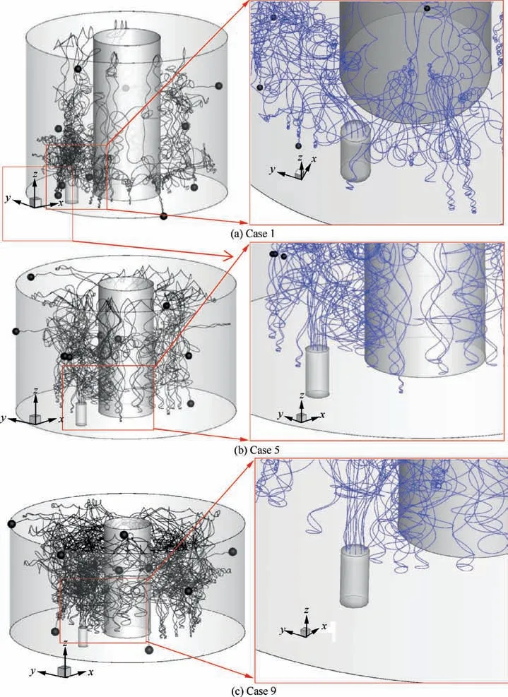
Fig. 15 Trajectories of primary electrons.
Fig. 10 shows the change of the primary electron average density along the circumferential direction. Clearly, with the increase of channel width, the difference of primary electron density between different circumferential positions decreases.Also,under the same channel width,this difference of the case reducing outer anode diameter is smaller.
Table 4 shows the primary electron average density,and the variance of density distribution, of each case. The variance is used to evaluate the uniformity. Table 4 indicates that: (1)Under fixed outer anode diameter, the primary electron density increase with the decrease of channel width, while its uniformity will become worse; (2) Under fixed inner anode diameter, the primary electron density will increase first and then decrease as the channel width increases, and its uniformity will become better. (3) The density in Case 5 is close to Case 1 and Case 3, but much higher than the other cases.Meanwhile, the uniformity in Case 5 is close to Case 6-Case 9, and much better than the other cases. Compared with Case 2,the average density of primary electrons can be increased by nearly 1.5 times in Case 5, meanwhile, the variance of density distribution can be reduced by more than 2 times.Hence,it can be concluded that, in all of these cases, the primary electron density and its uniformity in Case 5 is relatively better.
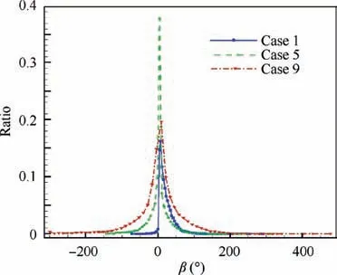
Fig. 16 Primary electron distribution function with the rotation angle β.
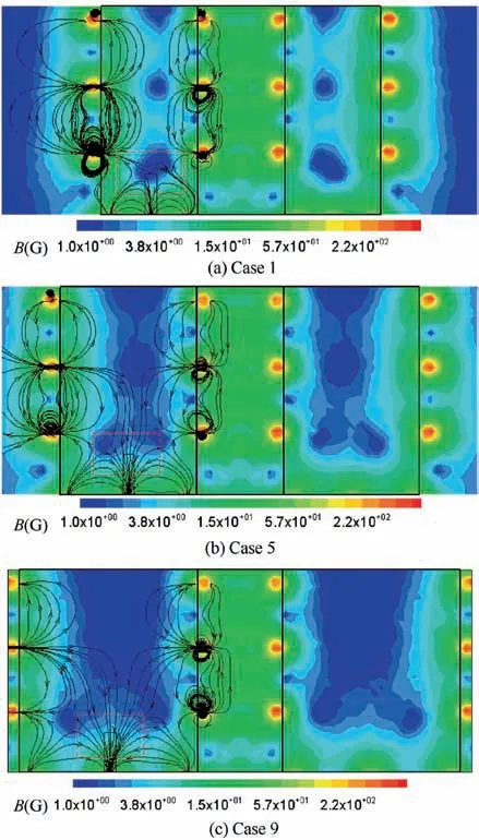
Fig. 17 Magnetic field structure under different channel width.
Fig. 11 and Fig. 12 show the ionization rate distribution and its change along the circumferential direction.Table 5 presents the average ionization rate of each case. These results indicate that the change trend of ionization rate is basically the same with that of primary electron. Also, Case 5 is relatively better.This means that if a better primary electron distribution is obtained, then a better ionization rate distribution can be obtained as well. Therefore, in the following content, we will focus on explaining the results obtained in this section by investigating the specific motion process of primary electron in each case.
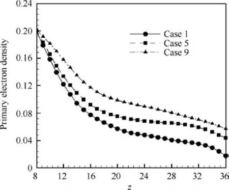
Fig. 18 Primary electron density along axis of cathode.
4.2. The reason for the variation in primary electron average density and uniformity of each case
The average density and uniformity of primary electron are basically determined by its average confinement length in the discharge chamber.The longer the average confinement length is, the more the number of primary electrons in the discharge chamber is and the higher the density tends to increase.Meanwhile,with the increase of the average confinement length,primary electrons are more likely to move from the cathode to the other side of the discharge chamber so that the uniformity tends to become better.Hence,in this section,the average confinement length of primary electrons is evaluated at first.50,000 simulation particles are used in each case, and these particles are set to be uniformly distributed in the cathode emitter. Their velocities are set to be 1. The collision process is ignored.Fig.13 shows the convergence of statistical average confinement length with number of particles in Case 1.It indicates that 50,000 simulation particles are enough to obtain the convergence results.
Table 6 presents the average confinement length of each case. Obviously, with the increase of channel width, the average confinement length of primary electrons increases, hence the primary electron uniformity become better as well.In addition,since the case increasing the diameter of outer anode has a longer average constrain length than that of the case decreasing the diameter of inner anode,the uniformity of Case 1,3,5,7 is better.
Ideally,the average confinement length of primary electron is only related to the discharge chamber volume V and the loss area on anode Ap, as shown in Eq. (17),

Since both the discharge chamber volume and the loss area can be written as a function of riand ro,we can obtain the relationship between average confinement length and the diameters of inner anode and outer anode. On the other hand,according to Eq. (15), we can obtain this relationship statistically. Fig. 14 presents the average confinement length of primary electron obtained by both Eq.(15)and Eq.(17).It can be found that, in an ideal case, the average confinement length increases linearly with the channel width. However, in fact,there is an inflection point for the increase of average confinement length, that is, the Case 5 or Case 6.
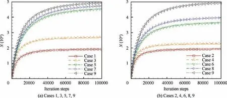
Fig. 19 Particle number in steady state under different channel width.
To better understand this inflection point, we present the trajectories of primary electrons in different cases, as shown in Fig. 15. It can be found that, in Case 1, the trajectories of primary electrons are distorted significantly at the cathode exit.However, in Case 5 and Case 9, their trajectories are basically a straight line upward. Since Cases 2,4,6,8,9 have the similar phenomenon, they are not shown here.
Fig. 16 shows the primary electron distribution function with the total angle β of primary electron rotating around the thruster axis. If one primary electron rotates clockwise, β is added the angle of rotation, otherwise β is subtracted the angle of rotation. In Case 1, the primary electrons are mainly distributed in the positive rotation angle.In Case 5 and Case 9,the distribution of primary electrons is basically symmetrical.This means that,in Case 1,the primary electron mainly rotates clockwise.
It can be seen from Fig. 17 that there is an obvious radial magnetic field above the cathode in Case 1, but not in Case 5 and Case 9.This radial field in Case 1 will seriously interfere with the motion of primary electrons,and guide it to the magnetic poles on the outer anode and the bottom anode. These primary electrons will be bound by the strong magnetic field,and has a larger probability of loss. However, in Case 5 and Case 9,primary electrons will mainly move to the channel center along the magnetic line. To show this clearly, Fig. 18 presents the primary electron density along the axis of the cathode. It can be found that, in Case 1, the primary electron density at z=20(i.e.the channel center)is about 34%of that at the cathode outlet, while, in Case 5 and Case 9, the values are 52% and 55%, respectively. Hence, it can be considered that, in Case 1, only 34% of primary electrons move to the channel center, while, in Case 5 and Case 9, more than 50%of primary electrons move to the channel center. Considering that Case 3 also has a magnetic field structure similar to Case 1, hence, in Fig. 14, the change of the average confinement length of primary electron inflects at Case 5, and after Case 5,the uniformity of primary electron is improved significantly.
Finally, Fig. 19 shows the particle number in steady state under different channel width. It can be seen that, at Case 5 or Case 6, the number of particles in the discharge chamber increases significantly. However, after these two cases, the increase of particle number is no longer obvious.
Since the primary electron average density is related to the discharge chamber volume and the primary electron confinement length, under the influence of these two factors, Cases 1,3,5,7,9 and Cases 2,4,6,8,9 show different trends. On the one hand, the increase of discharge chamber volume tends to reduce the average density of primary electrons. But on the other hand, with the increase of the primary electron average confinement length, the total number of primary electrons in the discharge chamber also increases in steady state, which makes the average density of primary electrons in the discharge chamber tend to increase.
5. Conclusions
In this paper, a 3D PIC-MCC model for primary electrons in annular ion thrusters is established. The confinement characteristics of primary electrons with different channel width are analyzed. The results show that:
(1) The density of primary electrons upstream of the ion optics on the cathode axis is about 5-50 times higher than that of the other side,which means that the density of primary electrons is obviously non-axisymmetric.The channel width has a significant effect on the average density and uniformity of primary electrons: The average density of primary electrons can be increased by nearly 1.5 times under the appropriate channel width, meanwhile, the variance of density distribution can be reduced by more than 2 times. Under fixed outer anode diameter,the primary electron density decreases with the increase of channel width,but its uniformity will become better. Under fixed inner anode diameter, the primary electron density will increase first and then decrease as the channel width increases, and its uniformity will become better as well. Under the same channel width,the uniformity of the case increasing outer anode diameter is better. Furthermore, the change trend of ionization rate is basically the same with that of primary electrons. Hence, if a better primary electron distribution is obtained, a better ionization rate distribution can also be obtained.
(2) With the increase of channel width,the average confinement length of primary electrons increases, hence the primary electron uniformity becomes better as well.The case increasing the diameter of outer anode has a longer average confinement length than that of the case decreasing the diameter of inner anode. Therefore, the uniformity of the case increasing the outer anode diameter is better.
(3) There is an inflection point in the increase of average confinement length, which is caused by the radial field above the cathode in the case before the inflection point.The radial field will seriously interfere with the movement of primary electrons, and guide them to the magnetic pole on outer anode and bottom anode. These primary electrons will be bound by a strong magnetic field,and has a lager probability of loss.After the inflection point, primary electrons mainly (more than 50%)move to the channel center along the direction of the magnetic field. This makes the average confinement length of primary electrons and their number in the discharge chamber increase significantly.
(4) The average density of primary electrons is related to the discharge chamber volume and the primary electron confinement length. The increase of discharge chamber volume tends to reduce the average density. But the increase of the primary electron confinement length makes the total number of primary electrons in the discharge chamber increase in steady state, and hence makes the average density tend to increase.
Declaration of Competing Interest
The authors declare that they have no known competing financial interests or personal relationships that could have appeared to influence the work reported in this paper.
Acknowledgements
This work was supported by National Natural Science Foundation of China (Nos. 11675040, 11702319) and the Fundamental Research Funds for the Central Universities of China(Grant No. DUT19LAB46).
 CHINESE JOURNAL OF AERONAUTICS2021年5期
- CHINESE JOURNAL OF AERONAUTICS的其它文章
- Ferrofluid moving thin films for active flow control
- Preliminary study on heat flux measurement data of TT-0 flight test
- An analysis and enhanced proposal of atmospheric boundary layer wind modelling techniques for automation of air traffic management
- Jet sweeping angle control by fluidic oscillators with master-slave designs
- Hot deformation behavior and microstructure evolution of the laser solid formed TC4 titanium alloy
- Electrochemical trepanning with an auxiliary electrode
