Influence of welding parameters on microstructure and mechanical properties of electron beam welded Ti60 to GH3128 joint with a Cu interlayer
Dein SONG, Ting WANGa,,*, Siyuan JIANG, Zhishang XIE
a State Key Laboratory of Advanced Welding and Joining, Harbin Institute of Technology at Weihai, Weihai 264209, China
b Shandong Provincial Key Laboratory of Special Welding Technology, Harbin Institute of Technology at Weihai, Weihai 264209, China
KEYWORDS Electron beam welding;Mechanical properties;Microstructure;Nickel alloy;Ti60 titanium alloy;Welding parameters
Abstract Effects of welding parameters on the microstructure and mechanical properties of Ti/Cu/Ni joint welded by electron beam were investigated. High welding heat input increased the melting quantity of Ti60 titanium alloy and promoted the formation of Ti-Cu intermetallic compounds(IMC) such as Ti2Cu and Ti3Cu4, increasing the brittleness of the joints. Low welding heat input was not conducive to the complete melting of the copper interlayer, and the unmelted copper reduced the performance of the joints. Under the optimal welding parameters, Ti-Ni IMCs in the weld would be replaced by (Cu, Ni) solid solutions ((Cu, Ni)ss). However, Ti-Cu IMC layers cannot be eliminated entirely by changing the welding parameters. The maximum tensile strength of the joints was 201 MPa. The fracture of the joints occurred at the Ti-Cu IMC layer, which was a typical brittle fracture.
1. Introduction
The high-temperature titanium alloy Ti60 is widely used in the aviation and aerospace industry because of its excellent hightemperature performance and low density.Ni-base superalloy GH3128 has unique mechanical properties at about 1000°C due to the addition of a large number of strengthening elements, such as W, Mo and Cr.The use of hightemperature alloys to manufacture critical components of the engine can significantly increase the working temperature of the engine and is an essential means to increase engine thrust.Therefore, welding the titanium alloy to the nickel-based superalloy can not only enhance the thrust of the engine but also significantly reduce the weight of the engine, which will powerfully help improve the research and manufacturing level of the spacecraft.
It is difficult to weld dissimilar metals, and the welding of titanium alloy to nickel alloy is no exception.Wang et al.studied the embrittlement of Ti/Ni electron beam welded joints and found that the joints could not be effectively welded due to the formation of intermetallic compounds(IMC)such as TiNi,TiNi and TiNi. The same conclusion was reached by Chatterjee et al.Significant attempts have been made to realize the welded joints. Chen et al.reported that Ti-Ni IMCs could be restricted and laser welded joints of Ti6Al4V to Inconel 718 can be obtained under the conditions of high welding speed and laser offset welding.
The addition of interlayer was considered as an essential method to realize the dissimilar metal welding.Copper is widely used as an interlayer because it has good metallurgical compatibility with chromium and nickel.Zhang et al.successfully realized the electron beam welding (EBW) of TA15 titanium alloy to GH600 nickel alloy by using a Cu interlayer.The addition of interlayer inhibited the formation of Ti-Ni IMCs, but the formation of the Ti-Cu IMC layer became the main factor leading to brittle fracture of joints.Gao et al.believed that although Ti-Cu IMCs were formed in the reaction layer, the brittleness of Ti-Cu IMCs was lower than that of Ti-Ni IMCs,which was the reason why copper was selected as the interlayer. In order to eliminate the Ti-Cu IMC layer,Liu et al.proposed Cu/Nb as filler metals to join Ti6Al4V to Ni alloy. Ti6Al4V and Nb were well bonded by the formation of (α+β Ti, Nb) solid solutions.
Moreover,EBW has unique advantages in dissimilar metals welding due to precise beam current control and vacuum protection environment.Wang et al.found that the melting content of Ti60 BMs was promoted by the high welding heat input and Ti-Cu compounds were formed. Although Ti/Ni joints can be obtained by using a Cu interlayer, the effects of welding parameters on the microstructure and mechanical properties of Ti/Cu/Ni joints have not been investigated yet.In this paper, pure copper interlayers were used to obtain the EBW joints of Ti60 titanium alloy to GH3128 nickel alloy.The effects of welding speeds and beam currents on the microstructures and properties of joints were discussed.
2. Experimental procedure
2.1. Materials
Nickel alloy (GH3128) and near α-type titanium alloy (Ti60)plates were employed as base metals (BM) in this paper. The chemical compositions of the BM are listed in Table 1 and Table 2,respectively.The physical properties of BMs are listed in Table 3.During the welding process, great temperature gradients and thermal stresses in joints will be generated due to the large differences in thermal conductivity and linear expansion coefficient exist between the two BMs.
2.2. Welding and analysis procedure
The BMs were cut into plates of 50 mm×25 mm×2 mm.According to the characteristics of electron beam welding with a large depth to width ratio, pure copper with a thickness of 0.5 mm was adopted as the interlayer.The plates polished with sandpapers were cleaned by ultrasound for 10-15 min.Prior to welding, the plates were wiped with the acetone solution to remove the grease on the surfaces. The filling materials shall be treated in the same way as the BMs. The processed plates were placed on the fixture, and the gap between the BMs and the interlayer shall be as small as possible. Then Ti60 plates and GH3128 plates were welded in the EBW equipment under a vacuum degree of 5×10Pa.The schematic diagram of the EBW process is shown in Fig.1.The process parameters of EBW are given in Table 4. The electron beam was focused on the centerline of the copper interlayer.
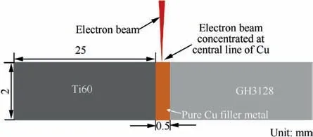
Fig. 1 Schematic diagram of EBW process.

Table 1 Nominal chemical compositions of Ti60 (wt%).

Table 2 Nominal chemical compositions of GH3128 (wt%).

Table 3 Physical properties of base materials.22,23

Table 4 EBW parameters of Ti60/Cu/GH3128.
Microstructures of Ti60/Cu/GH3128 joints were observed by OLYMPUS DSX510 optics microscopy (OM) and MERLIN Compact scanning electron microscopy (SEM) with energy dispersive spectroscopy (EDS). Tensile tests at room temperature were carried out by using INSTRON-5967 universal material testing machine under a loading rate of 1 mm·min. The dimensions of the tensile specimen are shown in Fig.2.The reported tensile strength was the average value from three specimens for the same joint. The reaction products of IMCs layer were analyzed by X-ray diffraction method.
3. Results and discussion
3.1. Effect of welding speed
Fig. 3 shows the surface appearances and macrostructures of cross-sections of the joints welded under different welding speeds.It can be seen from Fig.4,with the increase of welding speed, the widths of the fusion zones (FZs) reduced significantly. When the heat input was high, the weld cracked after welding.This phenomenon was mainly due to the slow welding speed (400 mm·min) leading to the diffusion of elements in the molten pool for a long time. Brittle Ti-Ni IMCs were formed by the combination of Ti atoms and Ni atoms in the molten pool. As the heat input decreased, good appearance joints without cracks were obtained under a speed of 600 mm·min. Pores formed by gases that did not escape in time were found inside the weld. Line energy was reduced by the high welding speed,and incomplete penetration was caused under a welding speed of 800 mm·min.
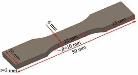
Fig. 2 Dimension of specimen used for tensile test.
The reaction time of various elements in the weld pool was reduced by the increase of welding speeds,which influenced the phase compositions of the weld.Therefore,Microstructures of Ti60/Cu/GH3128 joints with different welding speeds are shown in Fig. 5. The element compositions of points marked in Fig.5 are listed in Table 5.Compounds such as TiNi,TiNi and TiNiwere formed by the reaction of Ni atoms and Ti atoms near the crack.The formation of these compounds is the fundamental cause of crack formation.The barrier effect of the Cu interlayer was strengthened by the increase in welding speed. However, the Ti-Cu IMC layer was existed on the Ti60 side. Based on the Ti-Cu binary phase diagramas shown in Fig.6,the reaction layer near the titanium alloy side was mainly composed of TiCu IMCs, and Wang et al.also proved it. Scattered black bulk TiCu was also found in the IMC layer. Elmi Hosseini et al.investigated the effect of Cu interlayer thickening on the strength of Ti-steel joints.The lattice-like TiCu compounds and TiCu IMCs dispersed in the TiCu were also formed at the Ti-side. Tomashchuk et al.also proposed that α-Ti still existed inside the Ephase. The edge of the IMC layer was composed of gray TiCu. Zhang et al.also found TiCupresented a net structure. Tomashchuk et al.suggested that phase compositions(TiCu+TiCu) near the Ti side were not changed by the welding speed. There was also a small amount of cellular Tiat the fusion line on the Ti60 side.The thickness of the reaction layer decreased with the increase of the welding speed, which indicated that the thickness of the reaction layer could be controlled effectively with the reasonable welding speed.The middle zone of the weld was mainly composed of (Ni,Cu), and the change of welding speeds had little influence on the phases existing in the weld.The weld near the nickel side consisted of the white cellular Niand large black (Ni,Cu). It was worth noting that Ti-Ni/Ti-Cu IMCs were also distributed at the grain boundaries of the solid solutions at a welding speed of 400 mm·min, as shown in Fig. 5(c). There were also some highlighted spotty phases in the weld. Based on the data in Table 5,it was formed by the segregation of W and Mo during the weld solidification.
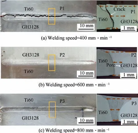
Fig.3 Macrographs and cross sections of electron beam welded Ti60/Cu/GH3128 joints with different welding speeds (Beam current=10 mA).
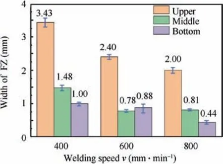
Fig.4 Width of FZ in joints with different welding speeds(Beam current=10 mA).
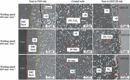
Fig. 5 Microstructures of welded joints with different welding speed (Beam current=10 mA).

Table 5 Chemical compositions (at%) of various phases A-K marked in Fig. 5.
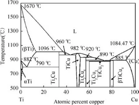
Fig.6 Binary equilibrium diagram of Ti/Cu.24
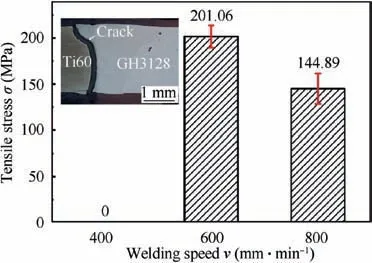
Fig.7 Tensile strength of Ti60/Cu/GH3128 joints with different welding speeds (Beam current=10 mA).
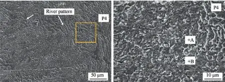
Fig. 8 Fracture surface morphology of Ti60/Cu/GH3128 joints.
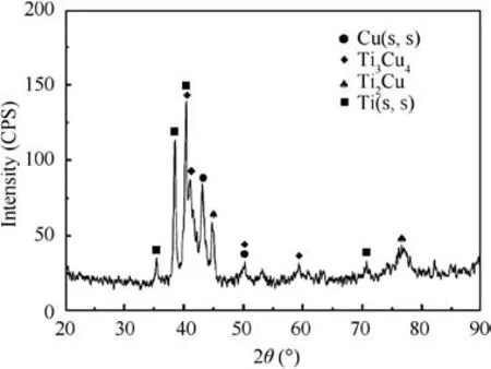
Fig. 9 XRD analysis results of fracture surface.
The tensile tests of all samples with different welding speeds were obtained to evaluate the mechanical performance of Ti60/Cu/GH3128 joints, as shown in Fig. 7. Under the welding speed of 400 mm·min, the tensile strength of the joint was 0 MPa due to the cracking of the joint after welding.The maximum shear strength of the joints was obtained under the welding speed of 600 mm·min. The fracture of the samples occurred in the IMC layer near the Ti60 side. Zhang et al.also received a similar conclusion.River patterns could be seenin the fracture morphology in Fig. 8, which proved that the fracture type of the joints was cleavage fracture mode. Wang et al.believed that the compositions of the fracture surface were mainly Ti-Cu IMCs, XRD results (Fig. 9) and EDS results (Table 6) of the fracture surface also confirmed this.The presence of IMCs increased the brittleness of the welds,and the joints were fractured along the grain boundaries under the action of tension.

Table 6 Chemical compositions of Spot A and B (at%).

Fig.10 Cross sections of electron beam welded Ti60/Cu/GH3128 joints with different beam currents(Welding speed=600 mm˙smin-1).
3.2. Effect of welding speed
Fig.10 shows macrostructures of the cross sections with different beam currents.In order to accurately analyze the influence of beam currents on the cross section,the widths of the upper,middle and lower parts of the welds with different beam currents were measured, as shown in Fig. 11. The cross sections of the welds were dumbbell-shaped. Unmelted copper was found in the lower part of the weld under the beam current of 8 mA. The effect of the change of beam currents on the width of middle welds was not noticeable.
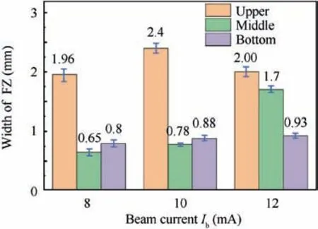
Fig. 11 Widths of FZs in joints with different beam currents(Welding speed=600 mm·min-1).
Fig.12 shows the microstructures of the zones near the Ti60 side with different beam currents and the elemental distribution of sample 5. It can be seen from Fig. 12 that there was an IMC layer near the Ti60 side and its thickness increased with the increase of beam currents, from 15 μm to 36 μm.The amount of heat input was determined by the value of the beam current. On the one hand, the solidification time of the weld pool was prolonged by the increase of beam currents.Ti, Ni, Cu and other elements had more time to flow and diffuse in the pool so that more Ti-Ni and Ti-Cu IMCs can be formed. On the other hand, the melting amount of the BMs was enhanced by the increase of beam currents. Therefore,the barrier effect of the copper interlayer was weakened, and the percentage of Ti atoms and Ni atoms would increase.Therefore, more Ti-Ni IMCs were nucleated in the molten pool. The concentration profiles of the major elements on the Ti60/weld metal interfaces are shown in Fig. 12(d). TiCu with a thickness of 24 μm was formed preferentially near the fusion line of the Ti60 alloy side. The region far from the fusion line was composed of TiCucompounds. Based on the above analysis, the beam currents should be reduced as much as possible under the condition that the filled layers can be completely melted.
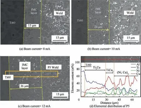
Fig. 12 Microstructures of welds near T60 side with different beam currents and elemental distribution of sample 5 (Welding speed=600 mm·min-1).
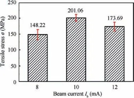
Fig. 13 Tensile strength of Ti60/Cu/GH3128 joints with different beam currents (Welding speed=600 mm·min-1).
Fig. 13 shows the tensile strengths of the joints with different beam currents.The tensile strength increased first and then decreased with the increase of beam currents, reaching a maximum value of 201 MPa under a beam current of 10 mA.When the beam current was small, the complete melting of the copper interlayer was prevented by the low heat input,and the unmelted copper was found near the Ti60 side.Unmelted copper was the main reason for the decrease of the tensile strength under the low heat input condition.The stress concentration was produced by Brittle IMC layers under the tension,which ultimately reduced the tensile strength of the joints.Therefore, the strengths of the joints decreased with the increasing thickness of the Ti-Cu IMC layer under the action of a large beam current. The middle zones of the welds were composed of Cu-based solid solutions (Cu) and (Cu,Ni). Zhao et al.claimed that the solute Ti was dissolved in the solvent Cu to form the Cu,which improved the plasticity and toughness of the welded metal. The stress in the IMC layer was alleviated by the ductile Cu, and the formation of cracks was inhibited.
4. Conclusions
The effects of welding speeds and beam currents on the microstructure and mechanical properties of Ti60/Cu/GH3128 joints were investigated. The conclusions were as follows:
(1) Reliable Ti/Ni joints were obtained by using a Cu filling layer. The optimum welding parameters (beam current:10 mA; welding speed: 600 mm·min) were also obtained. The maximum tensile strength of the joints was 201 MPa.
(2) Microstructures and mechanical properties were greatly affected by welding heat input. The optimum welding parameters can reduce the thickness of the Ti-Cu IMC layer, but cannot eliminate the IMC layer. The high welding heat input increased the thickness of IMC layers and even caused the joints to crack after welding.
(3) The weld microstructures were composed of Ti-Cu IMCs and (Cu,Ni)ss, the Ti-Cu IMC layers near the Ti60 side was the origin of the cracks in the brittle fracture of the joints.The stress was relieved and the performance of the joints was improved by the (Cu,Ni).
Declaration of Competing Interest
The authors declare that they have no known competing financial interests or personal relationships that could have appeared to influence the work reported in this paper.
Acknowledgement
This project was supported by Shandong Provincial Key Research and Development Program of China(2019JZZY010439).
 CHINESE JOURNAL OF AERONAUTICS2021年5期
- CHINESE JOURNAL OF AERONAUTICS的其它文章
- Ferrofluid moving thin films for active flow control
- Preliminary study on heat flux measurement data of TT-0 flight test
- An analysis and enhanced proposal of atmospheric boundary layer wind modelling techniques for automation of air traffic management
- Jet sweeping angle control by fluidic oscillators with master-slave designs
- Hot deformation behavior and microstructure evolution of the laser solid formed TC4 titanium alloy
- Electrochemical trepanning with an auxiliary electrode
