Machining of SiC ceramic matrix composites:A review
Qinglong AN, Jie CHEN, Weiwei MING, Ming CHEN
State Key Laboratory of Mechanical System and Vibration, School of Mechanical Engineering, Shanghai Jiao Tong University, Shanghai 200240, China
KEYWORDS Ceramic matrix composites;Machining;Material removal mechanisms;Quality;Surface integrity
Abstract Continuous fiber reinforced SiC ceramic matrix composites (FRCMCs-SiC) are currently the preferred material for hot section components, safety-critical components and braking components (in the aerospace, energy, transportation) with high value, and have triggered the demand for machining. However, the high brittleness, anisotropy, and heterogeneity of materials bring great challenges to machining, due to high mechanical and thermal loads, severe tool wear,and poor machining quality. With the increasing demand of FRCMCs-SiC parts, high-quality and high-efficient machining has become a hot issue.This review paper provides a detailed literature survey on the machining of FRCMCs-SiC. The material removal mechanism, defect form, and interfacial mechanical properties of FRCMCs-SiC were summarized. The machining processes of FRCMCs-SiC were introduced,and their respective advantages and disadvantages were compared.Given the low machinability (high hardness, high brittleness, anisotropy, and heterogeneity) of FRCMCs-SiC, preliminary experiments have proved that ultrasonic-assisted machining and laser-assisted machining have shown unique advantages in reducing force and tool wear,improving machining quality and machining efficiency. The machined surface integrity was discussed, the influence of process parameters on the machined surface quality was analyzed, and the machining defects of FRCMCs-SiC were summarized. But for FRCMCs-SiC, the existing quantitative evaluation of the machined surface integrity was weak and unsystematic.
1. Introduction
With the development of aerospace and national defense, hot section components of high thrust -weight ratio aeroengine,thermal protection systems of hypersonic vehicles, hot section components of heavy launch vehicle propulsion systems, and reusable rocket propulsion systems are in urgent need of new generation high-temperature materials. Taking aeroengine as an example, the materials of hot section components need to withstand the high temperature of about 1100°C.At present,the most commonly used high-temperature materials of aeroengine are nickel-base alloys, which can meet the service requirements utilizing ultra-high temperature thermal barrier coating.However, the combustion temperature of the newgeneration aeroengine will be further increased, and the temperature reaching the surface of the material will reach at least 1400-1700°C.The continuous increase of cooling has brought about an increase in the inefficiency loss of the aeroengine, so the scheme of nickel-base alloys combined with ultra-high temperature thermal barrier coating is difficult to meet the demand.Under the dual requirements of specific strength and high-temperature resistance,as shown in Fig.1,compared with metal materials, silicon carbide ceramic matrix composites (CMCs-SiC) have advantages.Continuous fiber reinforced ceramic matrix composites (FRCMCs) is a kind of tough ceramic material, which is toughened by continuous fiber reinforced phase, and optimized by suitable weak interphase between the SiC matrix and fibers.The toughening mechanism of FRCMCs is crack deflection and crack bridging,so high strength and high fracture toughness are both possessed.FRCMCs overcome the shortcomings of lowtemperature resistance and high density of metal materials,high brittleness and poor reliability of ceramic materials,poor oxidation resistance of carbon materials, and have excellent properties of lightweight, high-temperature resistance, good oxidation resistance, good corrosion resistance, good wear resistance, high damage tolerance. The United States, France,Japan, and other industrial powers have carried out a lot of researches on the preparation and application of ceramic matrix composite materials, such as the USA IHPTET (Integrated High Performance Turbine Engine Technology),UEET(Ultra-Efficient Engine Technology) plan, and Japan AMG(Advanced Materials Gas-Generator) plan, and have made many achievements in material development, preparation,and application.

Fig.1 Relationship between specific strength and temperature of alternative aerospace materials.4
At present,there are two kinds of FRCMCs-SiC which are widely used, carbon fiber reinforced SiC ceramic matrix composites (C/SiC) and SiC fiber reinforced SiC ceramic matrix composites (SiC/SiC). The difference in performance leads to their different application fields.
C/SiC composites are mainly used in friction materials and high-temperature materials with short service life. Due to the increasing demands on the speed, load, and safety of vehicles,ordinary friction materials will fail under extreme braking conditions. C/SiC composites have many excellent properties:high and stable friction coefficient, which is insensitive to changes in speed,load,and temperature;good wear resistance,not easy to scratch and stick to the surface of the friction couple,good run-in performance;strong environmental adaptability, good corrosion resistance, oil resistance, and humidity resistance; good mechanical properties; low density; long service life, so it is regarded as the first choice for the new generation of high-performance friction materials.In the field of aircraft braking systems, the brake discs developed by DACC(South Korean) for the F16 fighter have been widely used. In the field of limousine braking systems,C/SiC brake discs have been widely used in Porsche GT2(as shown in Fig.2(a)),Ferrari Enzo,Mercedes-Benz AMG,Corvette ZR1.In the field of high-speed train braking systems,C/SiC brake discs have been widely used in the French TGV NG, the British Heathrow Express train, and the South Korean TCV train. The C/SiC braking pads and brake discs of high-speed trains developed by Central South University have been applied to high-speed trains.Besides,C/SiC composites have been used in the brake discs of construction machinery,wind turbines and heavy-duty trucks.On the other hand, with the rapid development of aerospace technology, the near-space, and space astronautics technology involved in the new reusable hypersonic space suborbital or orbital maneuvering vehicle has attracted increasing attention, which puts forward strict requirements for the design and manufacture of the thermal protection systems.To meet the main technical characteristics (high reliability and reusability) of the aircraft during hypersonic flight, orbit or sub-orbit reentry, long-term in orbit reconnaissance, the thermal protection structural parts of the hypersonic aircraft are required to have excellent comprehensive performance,including heat protection, heat insulation, and loadbearing.C/SiC composites not only have good chemical and thermal stability, high specific strength, low specific gravity and low thermal expansion coefficient, but also have hightemperature resistance, wear-resistance, and insensitivity to cracks. So C/SiC composites are listed as key development materials of the thermal protection structural parts, such as nose cone (as shown in Fig. 2(b)), guide vane, wing and cover plate, for the new generation aerospace vehicles and hypersonic vehicles.For missile and rocket engines, the engine is developing in the direction of greater thrust, higher specific impulse, and higher thrust- weight ratio to increase the lift capacity. Therefore, it is inevitable to increase the area ratio of the nozzle extension, use the nozzle material with better temperature resistance and lighter weight.C/SiC composites has been used in the HM7 cryogenic engine of the European Ariane upper stage, the RL10B-2 engine of the Delta Ⅴupper stage, the RL10C-1 engine of the Atlas Ⅴ, the Vinci engine of the Ariane Ⅴupper stage, and the engine of China Yuanzheng 3(as shown in Fig.2(c)).Besides,C/SiC composites are used in aeroengines (such as outer flaps for M53-2 and M88-2 jet engine), satellite reflectors (such as the reflector of the German Donier satellite space telescope,the reflector of USA space telescope NGST, the reflector of Dutch radar telescope ATLID),sealing devices, magnetic vertical skid,coal water slurry pressurized gasifier burner.

Fig. 2 Application cases of Cf/SiC composites.
SiC/SiC composites are mainly used in high-temperature structural parts and functional parts with long service life.SiC/SiC composites have better oxidation resistance at high temperatures. Compared with nickel-base alloys, its working temperature can be raised by more than 200°C, which is suitable for manufacturing hot section components of aeroengine.It can reduce the weight of parts by more than 30%, improve the fuel efficiency by more than 10%, and greatly reduce the emission of nitrogen oxides and other pollutants. SiC/SiC composites have been the first choice for the hot section components of the new generation of high thrust-weight ratio aeroengines. Currently, hot section components such as exhaust nozzles of aeroengines, guide vanes, turbine blades, and turbine shroud are main applications.As the representatives of the industry,SNECMA(France)and GE(USA),two major global aeroengine manufacturing giants, have invested a lot in the design and preparation of SiC/SiC composites components, and developed a series of SiC/SiC hot section components with high reliability and long service life. Since the early 1980s, SNECMA has successfully developed SiC/SiC hot section parts such as engine nozzle flaps and exhaust cone(ARCOCE plug),which have been applied to CFM56 engines.Since the late 1980s, GE began to study the preparation technology of SiC/SiC composites and has completed the application verification of SiC/SiC hot section components such as the insert for the leading edge of turbine rear frame, the interstage platform, and the high-pressure turbine stator vane (as shown in Fig. 3(a)) of the aeroengine.The LEAP-X1C engine used in the COMAC C919 aircraft was developed by CFM (a 50/50 joint company of Safran Aircraft Engines and GE), and some of the hot section parts, such as the lowpressure turbine guide vane and high-pressure turbine shroud,use SiC/SiC composites. After investigation, the aeroengine hot section stator parts that have maturely applied SiC/SiC composites include first-stage and second-stage high-pressure turbine nozzles, first-stage high-pressure turbine shroud and low-pressure turbine guide vane of CFM LAP-X engine;combustion chamber inner/outer lining, first-stage high-pressure turbine shroud, first-stage and second-stage high-pressure turbine nozzles of GE9X engine; third-stage low-pressure turbine guide vane of F136 engine; combustion chamber lining(CERASEP A415,as shown in Fig. 3(b)) and flameholder(CERASEP A410).The aeroengine hot section rotor parts that have maturely applied SiC/SiC composites include lowpressure turbine rotor blades of F414 turbofan engine (as shown in Fig. 3(c)); low-pressure turbine rotor blades of GE9x engine. Rocket engines that have successfully applied SiC/SiC composites include: the integral thrust chamber of the liquid rocket engine jointly developed by Hyper-Therm and Air Force Research Laboratory;the SCD-SEP rocket test engine prepared by SEP (French).In the field of nuclear fusion, SiC/SiC composites are considered promising candidates for nuclear fusion reactors due to good radiation stability and low tritium permeation. The application of SiC/SiC composites in nuclear fusion reactors is mainly parts on the first wall, flow channel inserts and divertors of the blanket.As the material of first wall/blanket structure, SiC/SiC composites have good radiation damage resistance, good room temperature, and high-temperature mechanical properties,and can withstand high surface heat load. The blankets of the first wall made of SiC/SiC composites are mainly SCLL(Self-Cooled Lithium Lead) breeder blanket and HCCB(Helium-Cooled Ceramic breeder) blanket. The former includes PPCS-D and TAURO of EU, ARIES-I and ARIES-AT of USA, and the latter includes DREAM and ASSTR2 of Japan.The blankets of the flow channel inserts made of SiC/SiC composites are mainly DCLL (Dual-Coolant Lithium Lead) blanket, including FDS-II of China,PPCS-C of EU.The blankets of the divertors made of SiC/SiC composites are mainly PPCS-D and TAURO of EU, ARIES-AT of USA and DREAM of Japan.Besides,SiC/SiC composites can absorb the energy of electromagnetic waves and dissipate into thermal energy, which reduces electromagnetic wave reflection, and has excellent absorption performance at room temperature and high temperature.Therefore, SiC/SiC composites are particularly suitable for high-temperature stealth materials, used for heads of cruise missiles, nozzles of the engine, and the surface of hypersonic vehicles, to achieve the radar stealth function of weapon equipment.

Fig. 3 Application cases of SiCf/SiC composites.
For FRCMCs-SiC parts,the process of part preparation or repair of damaged parts is shown in Fig. 4. The SiC matrix preparation processes of FRCMCs mainly include polymer infiltration pyrolysis (PIP),chemical vapor infiltration(CVI),and reactive melt infiltration(RMI),etc.Different preparation processes have their advantages. During the preparation of the FRCMCs-SiC, the dimensional accuracy and geometric tolerance cannot be accurately guaranteed,and the surface quality is poor. Therefore, for the assembly surface and functional surface, machining is indispensable in the preparation process of FRCMCs-SiC parts.
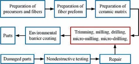
Fig. 4 Conventional process of preparation and repair of FRCMCs-SiC parts.
With the development of the preparation technology, the application of FRCMCs-SiC in aerospace, transportation,energy,and other fields is becoming more and more extensive.Machining technology has become one of the main technical bottlenecks restricting its extensive engineering application,while the research on the machining of FRCMCs-SiC is still in infancy. FRCMCs-SiC has the characteristics of high hardness, high brittleness, heterogeneity, and anisotropy, so the machinability is extremely poor. The microhardness of SiC is as high as 2840-3320 kg/mm, second only to diamond and cubic boron nitride (CBN), so the tool wear is severe during cutting. And its high brittleness is easy to cause cracks, pits,fiber damage, interface debonding, and other defects on the machined surface.Different from metal materials, there is no surface strengthening to improve the machined surface of FRCMCs-SiC after finishing. Therefore, the defects and damages caused by machining will permanently exist in the parts,which directly affect the thermal-mechanical properties, reliability,and service life of the parts.The existing machining processes have the limitations of poor machining quality, low precision, extremely low machining efficiency, and extremely high machining cost, and are unable to meet the high-quality and efficient requirements for the machining of FRCMCs-SiC parts, and are also difficult to meet the damage tolerance design and long-life service performance requirements. So far,the material removal mechanism and machining process of FRCMCs-SiC are still being explored.
This paper comprehensively reviews the research progress of the material removal mechanism, machining process, and surface integrity in the machining of FRCMCs-SiC (as shown in Fig. 5). By summarizing the achievements of different research teams, the challenges needed to be urgently solved of machining FRCMCs-SiC in a wide range of engineering applications are pointed out, and the further research directions of FRCMCs-SiC machining is prospected.
2. Material removal mechanism
Machining is a kind of subtractive manufacturing, which uses cutting tools or abrasive particles to remove materials. The material removal mechanism directly affects the physical phenomena during machining (force, heat, deformation, etc.) and the quality after machining. Therefore, it is of great significance to understand the material removal mechanism of FRCMCs-SiC for realizing high quality and high-efficiency machining.
2.1. Material removal mechanism based on orthogonal cutting
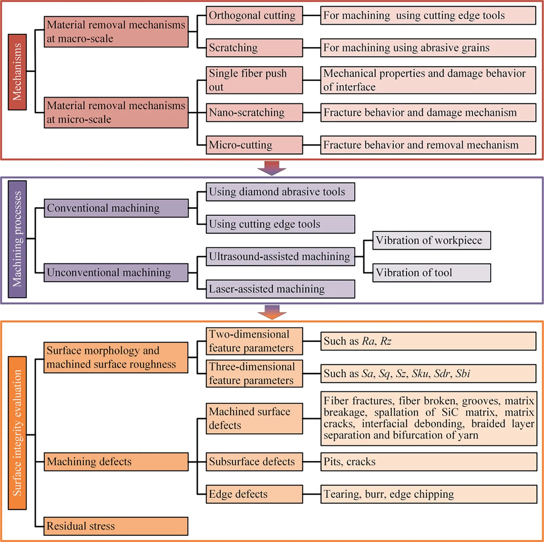
Fig. 5 Content overview on material removal mechanism, machining processes and surface integrity evaluation of FRCMCs-SiC.
For machining(such as milling,drilling,turning)using cutting edge tools, orthogonal cutting (OC) is the most commonly used basic experiment to study the material removal mechanism. In order to explore the material removal mechanism and ductile-brittle transition in the cutting,Diaz and Axinteconducted orthogonal cutting experiments on three typical fiber orientations of C/SiC composites.As shown in Fig.6,the material removal mechanism is significantly different along different fiber orientations and in different cutting depths.When the cutting thickness is small, the cutting is dominated by the shear behavior of composites when cutting along longitudinal fibers and the shear behavior of matrix when cutting along across fibers and transverse fibers, which is similar to the ductile removal. When the cutting thickness increases to a certain value, the cutting is dominated by the initiation and propagation of the fiber-matrix interface crack when cutting along longitudinal fibers and across fibers and the bending-induced fracture of fibers when cutting along transverse fibers, which is a typical brittle removal. On this basis,an analytical cutting model based on the inelastic behavior and fracture mechanics of orthotropic anisotropic brittle composites has been proposed, which is helpful to understand the surface integrity in the machining.
2.2. Material removal mechanism based on scratching
For machining (such as grinding) using abrasive, scratch experiments are often used to study the material removal mechanism. In order to study the grinding characteristics of 2D C/SiC composites in different fiber orientations,Liu et al.carried out a single abrasive scratch experiment with a diamond indenter on a grinding machine and analyzed the grinding mechanism.Within the scratch depth range(from 10 μm to 50 μm), the brittle removal combining the layered brittle fracture of carbon fibers and the cracking of SiC matrix was the material removal mechanism. Fig. 7 shows the scratch morphology of 0°-fiber and 90°-fiber along the scratch angle of 0°and 45°respectively.The tearing damage caused by bending and peeling off of carbon fibers is observed.Li et al.designed a new single abrasive scratch test by using CNC machining center, and carried out experiments along longitudinal fibers and along across fibers. Within the set scratch depth range(from 10 μm to 100 μm), the conclusion that brittle fracture(including matrix cracking, fiber breakage, fiber pull-out and fiber-matrix interfacial debonding) is the main material removal mechanism in grinding of C/SiC composites was also obtained,and brittle fracture led to severe subsurface damage.
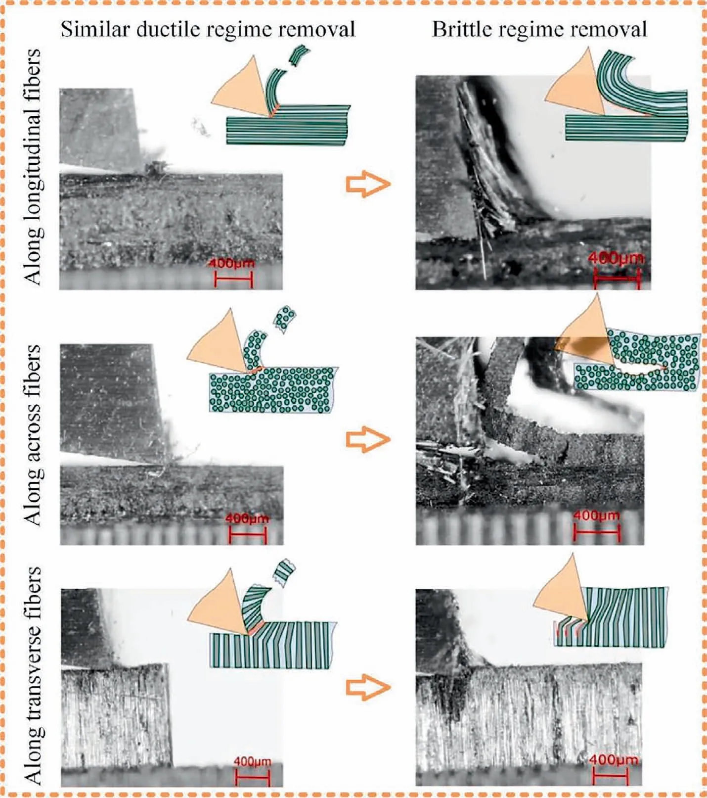
Fig. 6 Pictures of material removal captured by high-speed camera.44
Therefore, under large scratch depth, the brittle fracture,which is composed of matrix crushing, debonding of the fiber-matrix interface, and fiber fracture (bending fracture,compression fracture, and shear fracture), is the recognized material removal mechanism.
2.3. Nano/micro-scale material properties and removal mechanism
Fiber-SiC matrix interphase is an important component of FRCMCs-SiC. The debonding of weak interphase leads to stress relaxation at the crack tip, which achieves the purpose of material toughening and damage tolerance improvement.Weak interfaces are prone to damage such as debonding during machining,and free fibers caused by interphase debonding have an important influence on the material removal mechanism. Therefore, it is worth exploring the interfacial mechanical properties of FRCMCs-SiC,which provides a basis for the research of material removal mechanism and simulation modeling.
To evaluate the properties of fiber-matrix interphase,micromechanical tests are effective means, such as single fiber pull-out tests, microbond tests,fiber push-out tests, and single fiber fragmentation tests.For C/SiC composites, Zhang et al.used Berkovich indenter to push out and push back carbon fiber of 50-100 μm thick sample on Nanoindenter to test the interfacial shear strength and interfacial friction coefficient of pyrolytic carbon.Fig.8 shows the load-displacement curve and interfacial crack propagation diagram of the typical fiber extrusion process,which can be divided into four stages:elastic deformation of carbon fiber, push in stage (crack initiation),push out stage (crack propagation), and contact between indenter and matrix. Based on this, the interfacial shear strength can be calculated. Furthermore, the interfacial friction coefficient of pyrolytic carbon can be obtained by pushing the debonded carbon fiber back.This study provides a theoretical basis for the numerical simulation of interfacial mechanics and the analysis of the material removal mechanism in the machining.

Fig. 7 Scratch morphology.45
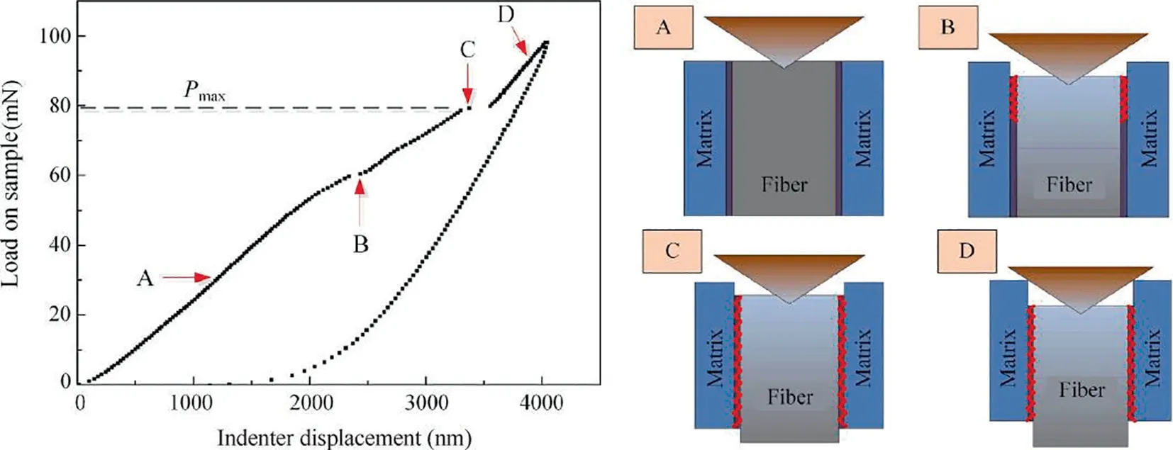
Fig. 8 Load-displacement curve and interfacial crack propagation diagram of single fiber push-out test with Berkovich indenter.48
Besides understanding the material removal mechanism on the macro scale,studying the material fracture and removal of FRCMCs-SiC at the micro/nano scale is of great significance for analyzing the mechanism of defect formation during material removal and improving machining quality. Nano scratch experiments is an effective method to study the fracture behavior and damage mechanism of materials.Generally, as the scratch depth increases, the elastic deformation, plastic deformation,ductile-brittle transition and brittle fracture appear in the scratches of single-phase hard and brittle materials in sequence.However, FRCMCs-SiC contain fiberreinforced phase, SiC matrix, and weak interphase, and the material removal mechanism in the brittle fracture is more complicated. The SiC matrix is always removed by crushing in the brittle regime. But the material removal mechanism of fibers in the brittle regime is more complicated. The highhardness SiC ceramic matrix has good support for fibers.When the scratch depth is sufficiently large, bending-induced fracture, compression-induced fracture, and shear-induced fracture are the fracture forms of fibers,which are consistent with the fracture forms of fibers in carbon fiber-reinforced polymer (CFRP).But when the scratch depth is small, the brittle fracture mode of the fiber changes. Chen et al.conducted nano-scratch experiments on unidirectional C/SiC composites along different fiber orientations. According to whether the brittle fracture of the carbon fiber occurs inside the fiber or the whole fiber as the smallest unit, the brittle regime of C/SiC composites can be subdivided into micro brittle fracture regime and macro brittle fracture regime. In the micro brittle fracture regime,under the extrusion of the indenter, cracks initiate inside the carbon fiber and propagate between the graphite crystallites, resulting in the material removal of the fiber.In the macro brittle fracture regime,fibers are debonded from the SiC matrix under the extrusion of the indenter, and then bending fracture (or compression fracture and shear fracture) occurs. Fig. 9 shows graphic illustrations of the micro-macro brittle fracture transition of carbon fibers when scratching along different fiber orientations. Different material removal mechanisms form different machined surfaces and cause different machining defects.
For SiC/SiC composites, Diaz et al.obtained the machined surface by drilling. The material fracture behavior and removal mechanism in the cutting was understood based on the microstructure, residual stress, and element distribution. The material fracture behavior and removal mechanism of each phase were summarized, as shown in Fig. 10. Hi-Nicalon fiber is composed of 3C SiC nanocrystals and graphite microcrystals, which are removed by a brittle transgranular cleavage fracture during cutting. The SiC matrix prepared by the MI process is composed of 6H-SiC microcrystalline,which simultaneously occurs ductile removal and brittle fracture (intergranular fracture) during cutting. The interphase layer of CVI-SiC is formed by ultrafine columnar crystals, which fracture along the columnar direction during cutting.The fracture behavior and material removal mechanism of each phase are different due to the difference in the microstructure.
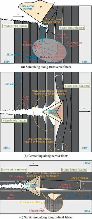
Fig. 9 Graphic illustrations of micro-macro brittle fracture transition of carbon fibers caused by the increase of scratch depth.53
According to the researches of the mechanism,the physical phenomena of SiC ceramic matrix composites in the mechanical material removal process are well understood, such as material fracture mechanism, material removal mechanism,interfacial mechanical properties,and material damage behavior.These basic works are beneficial to analyze the mechanism of machined surface generation and machining defects in the machining of FRCMCs-SiC, and also have guiding significance for process optimization.
3. Machining process of FRCMCs-SiC
The processing technology of FRCMCs-SiC is the key factor to promote industrial application. NASA mentioned in the‘‘Aeronautical technologies for the twenty-first century” that the preparation process and processing technology of ceramic matrix composites will be given priority in the future research plan of engine materials.The processing technologies of FRCMCs-SiC mainly includes conventional machining (CM)(such as grinding,milling,drilling),ultrasonic-assisted machining (UAM) and laser-assisted machining (LAM), nontraditional machining (NTM) (such as abrasive waterjet(AWJ) machining, electrical discharge machining (EDM),pulsed laser ablation (PLA)), etc. Besides, some basic researches (such as orthogonal cutting and scratching) have also been carried out. Papers on the processing of FRCMCs-SiC were collected (since the core contents of most theses had been published in various journals, so the theses are not counted in the figure), and were classified, as shown in Fig. 11. Since 2015, the number of publications on FRCMCs-SiC processing has grown significantly, especially for machining,and most of the research teams are from China.
Different processing technologies have different functions.Machining is mainly used for the material removal of large machining allowance and obtaining high-precision/highquality structures and surfaces. AWJ is mostly used for through cut.EDM is suitable for obtaining complex structural parts. PLA is mainly used for the processing of fine structures(micro-holes, micro-grooves).
Because of the wide application and various challenges of FRCMCs-SiC machining, the following is an overview of machining, including CM, UAM, LAM.
3.1. Conventional machining (CM)
Conventional machining is indispensable in the study of machining. It is of great significance to understand the material removal mechanism of FRCMCs-SiC during machining,optimize the machining parameters, and provide directions for the improvement of machining processes. In this section,the conventional machining of FRCMCs-SiC will be discussed. Grinding and cutting will be introduced separately.
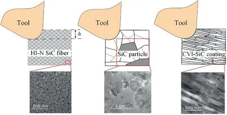
Fig. 10 Material removal mechanism of each phase of SiCf/SiC composites during cutting.54
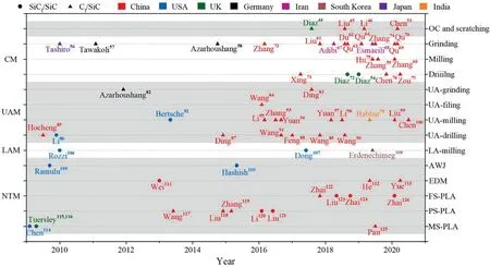
Fig. 11 Summary of publications on processing of FRCMCs-SiC.109-126
As hard materials, SiC matrix and fibers cause severe tool wear during machining. Therefore, at the current research stage, most researchers use diamond abrasive tools to study the grinding process. For the study of surface grinding, on the one hand,it is to study the processing technology of planar structure, on the other hand, it is to explore the influence of grinding parameters and the material removal mechanism in the grinding process.Tashiro et al.conducted a dry grinding test of C/SiC composites,and found that carbide tools cannot be used due to catastrophic tool wear,and diamond wheels are better than WA wheels. Tawakoli and Azarhoushangdeveloped a metal-bonded segmented diamond wheel and proposed that intermittent grinding can reduce the grinding force and grinding temperature, but the acting force on each abrasive is large, and the main wear mechanisms of the segmented wheel are the inter-crystalline grain fracture and grain pull-out. Zhang et al.conducted grinding experiments on three typical fiber orientations of unidirectional C/SiC composites, and proposed that besides grinding parameters (feed rate, grinding depth, grinding speed), fiber orientations also greatly affected grinding force and surface morphology, and preliminary proposed the material removal mechanism of C/SiC composites in grinding. As shown in Fig. 12, brittle fracture is the main material removal mechanism in grinding.When grinding along across fibers, the interface is subject to the first failure form (opening mode), and the fiber is mainly subjected to shear stress. When grinding along longitudinal fibers, the interface is subjected to the second failure mode(shearing mode), and the fiber is subjected to in-plane shear stress. When grinding along transverse fibers, the interface is subjected to the third failure mode (tearing mode), and the fiber is subjected to shear stress and tensile stress. Liu et al.conducted grinding experiments on 2D C/SiC composites,and systematically studied the effects of grinding parameters on the grinding force,force ratio,specific grinding energy,surface topography, surface roughness, and grinding chips. Du et al.explored the effects of different grinding directions(essentially different fiber orientations)on the grinding process and surface roughness of 2D C/SiC composites. Qu et al.studied the effects of grinding parameters on the surface roughness of 2.5D needle C/SiC composites, and proposed that the changes of grinding parameters mainly play a role by changing the undeformed chip thickness. Qu et al.also mentioned that the fiber orientation angle was an important parameter that affected the grinding process of C/SiC composites. In general, grinding force and surface roughness increase with the increase of grinding depth and feed rate,and decrease with the increase of grinding depth,and fiber orientation is also an important factor. As for the material removal mechanism in the grinding, there is consensus that brittle fracture is the main removal mechanism.Under the respective experimental conditions, the material failure modes are basically described as matrix breakage, fiber fracture, and interfacial debonding.
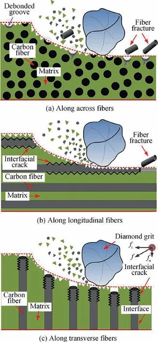
Fig. 12 Schematic diagrams of grinding along three typical directions.59
Because of the problems of high force, serious wheel wear,and low surface quality in grinding, minimal quantity lubrication (MQL) was tried. MQL is a green, clean and efficient cooling and lubrication method, which has been widely used in the machining of ceramics and various metals.Based on this successful application, MQL is tried to be used in the machining of FRCMCs-SiC.Adibi et al.and Esmaeili et al.proposed the application of MQL when grinding C/SiC composites. By comparing with dry grinding, it was found that MQL grinding effectively reduced grinding force and surface roughness, alleviated grinding wheel wear, and improved grinding efficiency. Qu et al.studied the influence of nozzle direction, air pressure, oil flow rate and nozzle distance on the MQL grinding performance of unidirectional C/SiC composites, and optimized based on grinding force and surface roughness. Furthermore, Qu et al.proposed carbon nanofluid MQL (NMQL) to grind C/SiC composites, and verified the effectiveness of NMQL in reducing grinding force and improving surface roughness through experiments. But it is worth noting that FRCMCs-SiC contains pores limited by the preparation process. Therefore, the liquid in the MQL grinding process may penetrate into the pores of the workpiece through capillary action,and it is difficult to remove.Whether these liquids will directly affect the performance of the parts is worth discussing, and in some extreme service environments(ultra-high temperature, vacuum), these liquids may directly damage the FRCMCs-SiC parts through vaporization. Therefore,just like CFRP,the use of MQL(or other coolants)in the machining of FRCMCs-SiC requires further cautious research.
For hole machining, Xing et al.conducted drilling experiments of unidirectional C/SiC composites by using brazed diamond drills, analyzed the influence of drilling parameters on thrust force, delamination factor, hole surface quality,and tool wear,and adopted supported graphite plate to reduce the exit damage. The experimental results showed that high speed and low feed rate were effective in improving the drilling quality.
Because of the high hardness of FRCMCs-SiC, diamond abrasives are used in most machining processes,but the limitations of low machining efficiency and low machining accuracy are obvious. The use of cutting edge tools for machining can improve machining accuracy and increase machining efficiency. Diaz et al.tried to use the cutting process to machining SiC/SiC composites. As shown in Fig. 13, the random positions and sizes of warp, weft, and porosity in the matrix were simulated by a probabilistic method based on the random relative content of fiber and matrix faced by the main cutting edge of the bit. Considering the randomness of the inhomogeneous structure of the material,the hard characteristics of the material are coupled to calculate the tensile stress of the tool according to its diameter. And the influence of material heterogeneity and high hardness on the premature tool breakage of small diameter bit in the drilling of SiC/SiC composites was analyzed. Zhang et al.used carbide tools to mill C/SiC composites, studied the influence of milling parameters on milling force and surface roughness and established a milling force analysis model of C/SiC composites considering the randomness of fiber distribution and tool wear.
Due to the ultra-high hardness of FRCMCs-SiC, the wear of carbide tools in the machining is sharp and difficult to meet the demand. In order to solve the catastrophic tool wear of carbide tools,Hu et al.,Chen et al.and Zou et al.respectively discussed the feasibility of polycrystalline diamond(PCD)tools used in milling and drilling of C/SiC composites,and obtained good effects.Hu et al.successfully explored the use of PCD tools for slot milling 2D C/SiC composites. Chen et al.explored the use of PCD tools for drilling experiments,analyzed the impact of thrust force on the hole exit defects,discovered the transition of the material removal mechanism of carbon fibers in the brittle regime caused by changes in drilling parameters, and creatively defined the micro brittle fracture and macro brittle fracture. As shown in Fig. 14, with the increase of cutting depth, the material removal mechanism of carbon fibers changes from micro brittle fracture to macro brittle fracture. The micro brittle fracture of carbon fibers in different fiber orientations is caused by the initiation and propagation of microcracks generated by the extrusion of cutting edge.However,the macro brittle fracture in different fiber orientations is different, including bending-induced fracture,compression-induced fracture, shear-induced fracture, and interfacial debonding. Zou et al.studied the effect of PCD tool angles (clearance angle and point angle) on the thrust force,hole exit damage and surface quality in 2D C/SiC composites drilling and tried to improve the efficiency of hole exit quality evaluation by using the damage identification method based on image processing technology.

Fig. 13 Probability modeling of tool imbalance in cutting of hard heterogeneous materials (SiCf/SiC composites).72
Obviously, conventional machining of FRCMCs-SiC can be realized by using superhard tools (diamond abrasive tools,PCD tools).However,the disadvantages of CM are inevitable,such as high force during the machining, poor machined surface quality, serious machining defects, and serious tool wear.In order to meet the indexes of the machining quality, the machining efficiency is often sacrificed in the production,which is detrimental to reduce the machining costs.
3.2. Ultrasonic-assisted machining (UAM)
In the process of CM,the problems of large cutting(grinding)force, many machining defects, large surface roughness and low machining efficiency need to be solved.UAM technologies are applied to FRCMCs-SiC. For hard and brittle materials,UAM has an excellent effect in improving machining quality and efficiency.For the surface,slot,hole,and cavity structures of FRCMCs-SiC parts, corresponding UAM are proposed respectively. In this section, UAM processes will be introduced for different structural features to be machined.
Grinding is the main process of high-quality surface finishing.Azarhoushang and Tawakoliinvented a block sonotrode to achieve ultrasonic assisted grinding of C/SiC composites on a traditional grinder by ultrasonically vibrating the workpiece,and proved that the grinding force was reduced by 20% and the surface roughness was reduced by 30% under ultrasonic vibration. Ding et al.clamped the diamond brazed grinding wheel on the ultrasonic tool holder, realized the ultrasonicassisted grinding of C/SiC composites through the ultrasonic vibration of the wheel, and proved that the normal grinding force was reduced by 9-21%, the tangential grinding force was reduced by 9.7-19.4%, and the maximum reduction percentage of surface roughness was 12%. Workpiece vibration and tool vibration are two ways to realize UAM (as shown in Fig.15).Based on the principle of relative motion,the effect of the two methods is the same, and which one should be selected in the production should take into account the existing equipment and cost.
For the inner surface machining of deep cavity parts, the tool holder and parts are easy to interfere, and the machining accuracy and quality are difficult to guarantee,which are great challenges.Wang et al.elaborated the concept of ultrasonicassisted filing (UAF) and first applied it to the machining of C/SiC composites. Compared with conventional grinding(CG) and conventional filing (CF), UAF reduced surface roughness and improves shape accuracy.
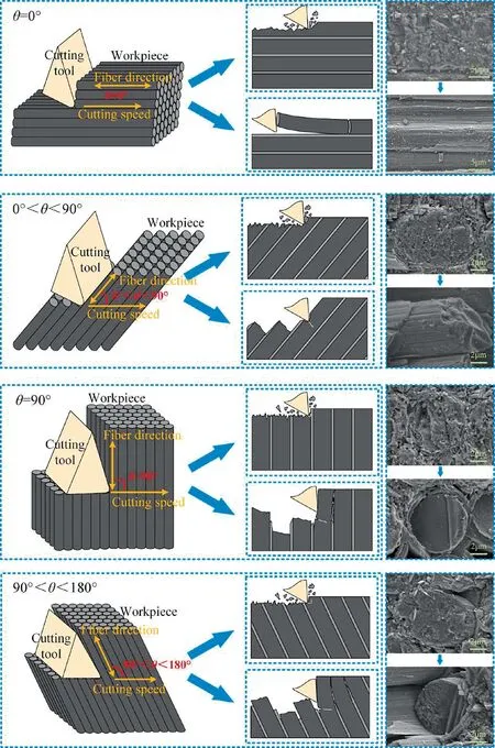
Fig. 14 Material removal mechanism of carbon fibers in cutting of Cf/SiC composites.76
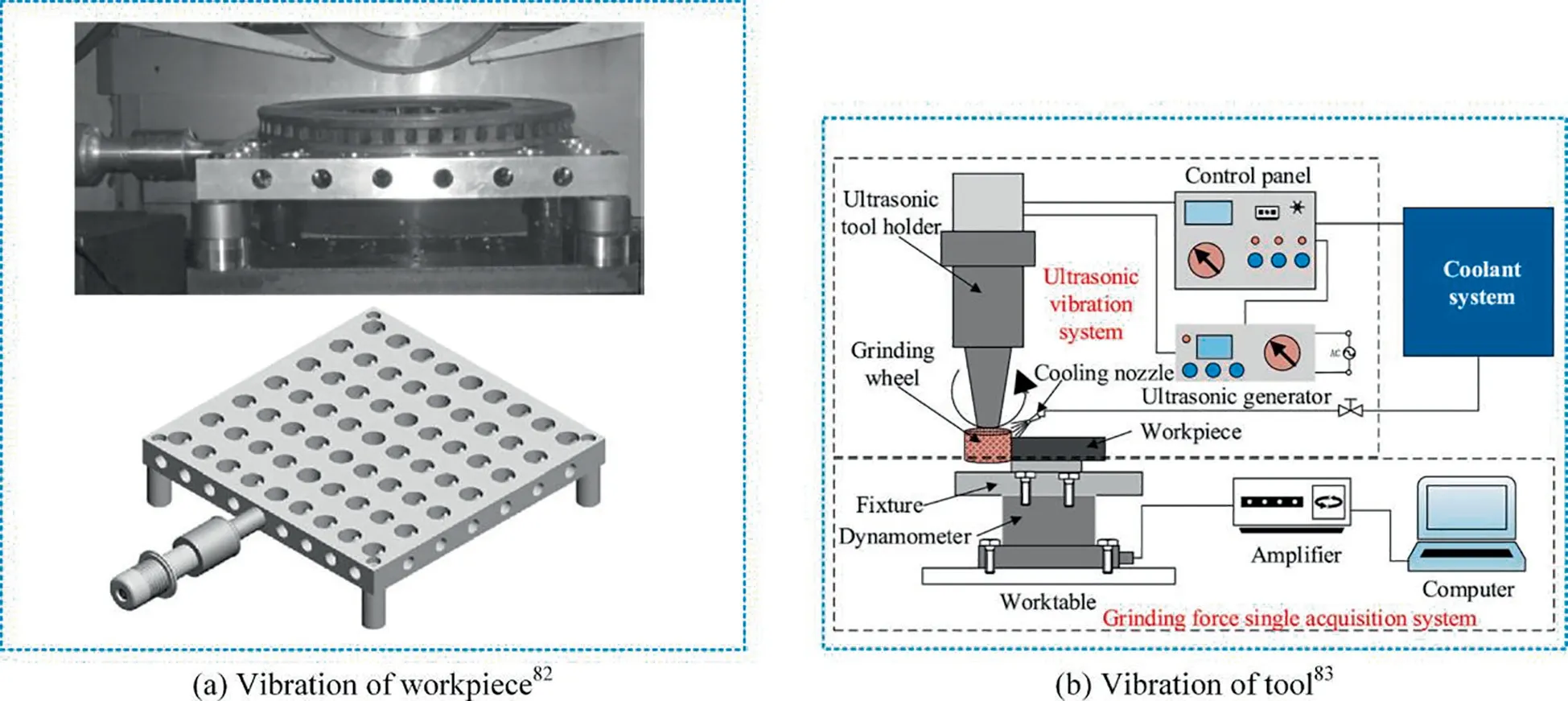
Fig. 15 Two modes to realize RUM.
For larger-size holes, drilling is essential. For FRCMCs-SiC,the machining technology which combines diamond abrasive tool and UAM is concerned. Hocheng et al.used abrasive slurry and stainless steel tools to carry out ultrasonic-assisted drilling experiments on an ultrasonic drilling machine and first proposed that ultrasonic-assisted drilling of C/SiC composites had advantages in machinability and cost compared to other feasible machining processes.Li et al.pioneered the use of rotary ultrasonic machining (RUM) in the drilling of SiC/SiC panels, studied the influence of machining parameters (spindle speed, feed rate, ultrasonic power) on the force, material removal rate, and hole quality, and proposed that RUM significantly reduced the cutting force by about 50% and improved the machining efficiency by about 10%,and high-quality holes could be obtained under the appropriate machining parameters. Ding et al.used diamond core drill to drill C/SiC composites, and studied the influence of machining parameters on drilling force and drilling quality.Compared with conventional drilling (CD), in rotary ultrasonic drilling, the thrust force was reduced by 7.4%-23%,the torque was reduced by 8.5%-47.6%,the surface roughness of hole wall was reduced and the maximum reduction percentage was 23%. Feng et al.and Wang et al.discussed the RUM of C/SiC composites (as shown in Fig. 16(a)). The effects of machining parameters (spindle speed, feed rate,ultrasonic amplitude) on the exit defects and the microstructure of the machined surface were studied. It is proposed that the ultrasonic vibration of diamond abrasive tools improved the surface quality by changing the mechanism of fiber fracture, and the tearing defect at the hole exit was averagely reduced by more than 50%, but the mechanism has not been studied in depth. Wang et al.analyzed the correlation between cutting force and ultrasonic power and proposed that the adverse effect of tool wear on the increase of cutting force was restrained by adjusting the tuning frequency. In addition,Wang et al.proposed to use a compound step-taper drill (as shown in Fig.16(b))to reduce the exit damage in the RUM of C/SiC composites, and the experimental results showed that the tearing size was reduced by 30%. Overall, the effect of RUM in reducing drilling force, hole wall roughness and machining defects on hole exit is considerable.
RUM is also used in slot milling and face milling.Bertsche et al.first proposed the application of rotary ultrasonic slot machining(RUSM)in the milling of FRCMCs-SiC(as shown in Fig. 17(a)), and optimized the milling parameters and designed diamond tools.Compared with the conventional diamond grinding, RUSM reduced the radial force by 20%,reduced the axial force by 9%, reduced tool wear by 36%,but increased the surface roughness slightly, which may be related to the influence of fiber orientation during measurement. Based on the grinding principle and parameter fitting,Zhang et al.and Yuan et al.established a dynamic cutting force model for side-milling of C/SiC composites in RUM,and analyzed the change of cutting force with spindle speed,feed rate and milling width based on the model and experiment. Li et al.used the conical diamond abrasive tool for rotary ultrasonic face milling (RUFM) (as shown in Fig. 17(b)), and proposes that compared with conventional milling, the machining efficiency of RUFM was improved by 5.8 times and the surface quality of RUFM was improved by 54.4%. Different from cylindrical diamond tools, the conical surface of the tool made abrasive grains cut intermittently under ultrasonic vibration(in other words,the abrasive grains and the workpiece have periodic separation characteristics).The milling force model of C/SiC composites was established based on the abrasive kinematics and indentation principle,and the influence of milling parameters on milling force was analyzed. Based on the research of Li, Yuan et al.proposed to quantify the material removal mode by the maximum penetration depth of diamond abrasive in the workpiece material and proposed the transition of material removal mechanism from ductile to brittle fracture. Babbar et al.used diamond abrasive tools for rotary ultrasonic milling of C/SiC composites. The effects of material density, feed speed, and axial milling depth on the machining were investigated.It was found that as the material density increased,machinability decreased but surface quality improved.
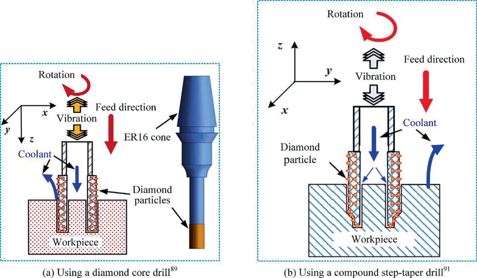
Fig. 16 Rotary ultrasonic machining-drilling.
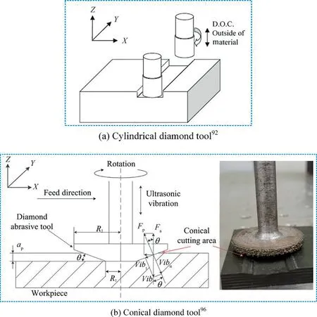
Fig. 17 Rotary ultrasonic machining-milling.
Besides ultrasonic-assisted machining with diamond abrasive tools, ultrasonic-assisted milling with cutting edge tools is also an option. Liu et al.performed ultrasonic-assisted milling experiments of C/SiC composites by using CVD diamond coated carbide milling tool. Compared with conventional milling, UAM respectively reduces the wear band width of the side edge and the bottom edge flank by 28.06%and 33.12%. But obviously, for C/SiC composites, the wear of diamond coated carbide tools is still very serious. Chen et al.studied the feasibility of using PCD tools for C/SiC composites UAM (as shown in Fig. 18). The experimental results showed that the appropriate ultrasonic amplitude effectively reduced the surface roughness, but increased the specific milling energy. The nano-scratch experiment proved that there is a micro-macro brittle fracture transition of C/SiC composites during material removal.This transition still exists in milling.The high-frequency hammering of the cutting edge on the workpiece promotes the initiation and propagation of micro-cracks within the carbon fiber due to the appropriate tool amplitude, thereby promoting the removal of the carbon fiber material with micro-brittle fracture, which effectively reduces the machined surface roughness. And the cuttingedge hammering effect reduces the tensile residual stress, and even generates compressive residual stress.
Extensive experiments have proved that, for both abrasive tools and cutting-edge tools, UAM is beneficial to reduce machining force, machined surface roughness, and machining defects, which is of guiding significance for the machining of FRCMCs-SiC. From the perspective of machining quality,UAM can effectively reduce machining defects and machined surface roughness. From the perspective of machining cost(without considering the equipment cost), compared with CM,UAM is beneficial to improve machining efficiency under the same machining quality indexes, thereby reducing the machining cost. But the effects of high-frequency vibration of cutting edge and abrasive grains on the material removal mechanism and damage behavior of FRCMCs-SiC need to be further explored.
3.3. Laser-assisted machining (LAM)
Due to the high hardness and high brittleness of FRCMCs-SiC, the material is removed by brittle fracture during cutting and grinding,so the machined surface quality is poor,and the tool wear is serious. Inducing strength loss of materials through high temperature during machining is an effective method to solve the poor machinability caused by high hardness and high brittleness high hardness and high brittleness,thereby extending the tool life, improving machining quality and machining efficiency.LAM provides an effective way for the machining of ceramics,glass,hard and brittle metals, and other materials.However, for FRCMCs-SiC,LAM process is still in the exploratory stage. Rozzi and Bartonfirst used the laser to preheat the C/SiC composites,and then used a PCD tool to remove the material (Fig. 19(a)). Compared with conventional milling, the cutting force during LAM was greatly reduced by 40%, which was conducive to improving machining efficiency and reducing production costs. Therefore, LAM is a feasible process for FRCMCs-SiC. For laser-assisted micro-slot milling of SiC/SiC composites (as shown in Fig. 19(b)), Dong et al.optimized the machining parameters based on the finite element simulation of the three-dimensional transient temperature field and studied the influence of laser heating on tool wear and tool life. Compared with conventional milling, LAM reduced tool wear by up to 76%, improved tool life by up to 3.8 times,and reduced the tool costs by up to 32.3%. Erdenechimeg et al.optimized the machining parameters of laser-assisted milling of C/SiC composite laminates.The preheating temperature was simulated based on the finite element method to determine the effective cutting depth. Based on the Taguchi method,the experimental design was performed, and the variance analysis was used to analyze the experimental results.When other machining conditions were the same, LAM reduced the cutting force by up to 40.7%and reduced the surface roughness by up to 33.8%.
Limited by the equipment, there is relatively little research on LAM of FRCMCs-SiC,and the focus is on feasibility analysis. For FRCMCs-SiC, LAM is a feasible process to reduce machining force and improve machining quality. However,more exploration is needed,such as the effect of laser on material thermal damage, process parameter optimization, LAM equipment development.
The advantages and disadvantages of FRCMCs-SiC machining processes are summarized in Table 1.
4. Machining quality of FRCMCs-SiC
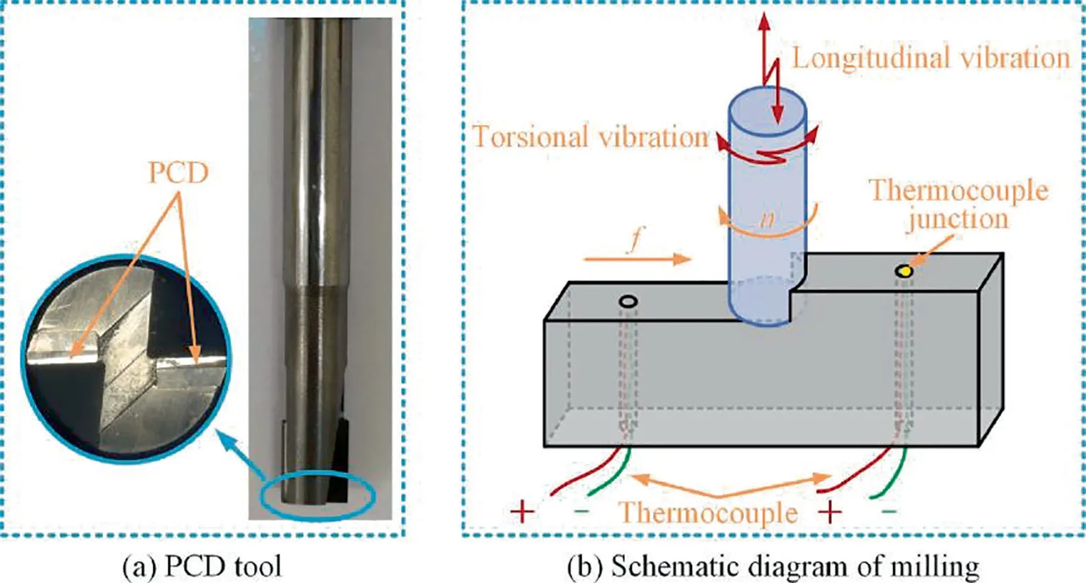
Fig. 18 Ultrasonic assisted milling.100
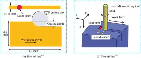
Fig. 19 Laser-assisted milling.

Table 1 Advantages and disadvantages of FRCMCs-SiC machining processes.
The service environment of FRCMCs-SiC is generally extremely harsh. Besides the original defects generated during the preparation of the material, surface integrity also affects service performance and fatigue life.Unlike metal materials,there is no surface strengthening process to improve the machined surface of FRCMCs-SiC. Therefore, the defects and damages caused by machining will permanently exist in the parts,which directly affect the thermal-mechanical properties, reliability,and service life of the parts. Therefore, it is valuable to study the mechanism of machining defects of FRCMCs-SiC and to explore the few-defects or non-defects machining process of FRCMCs-SiC.
4.1. Surface morphology and machined surface roughness
The roughness of machined surface is the most common index to evaluate the machined surface quality. In the studies, both two-dimensional feature parameters (such as Ra,Rz)and three-dimensional feature parameters (such as Sa, Sq, Sz, Sku, Sdr, Sbi),are used. However, in view of the anisotropy and heterogeneity of FRCMCs-SiC, two-dimensional feature parameters may be difficult to accurately evaluate the roughness of the machined surface. Therefore, three-dimensional feature parameters have been used more. Generally, the 3D surface morphology is obtained by non-contact optical measurement methods (as shown in Fig. 20), and then threedimensional feature parameters are obtained.
Material properties play a decisive role in the machined surface quality.As a typical anisotropic and heterogeneous material, the effect of carbon fiber orientations and machining direction on machined surface roughness obviously exists.Zhang et al.conducted grinding experiments on three typical fiber orientations,as shown in Fig.21.The results showed that both Ra and Rz followed the following rule: Longitudinal >Normal >Transverse. For surface grinding using diamond wheels, Qu et al.defined the deflection angle as α, β,γ according to the reference plane, and proposed that when α=90°,β=90°,γ=0°,Sa and Sz were the minimum.Wang et al.discussed the effect of fiber orientation angle on surface roughness when using a diamond core drill for C/SiC composites rotary ultrasonic drilling, and proposed that Sq was the smallest when the angle was 90°. In addition, the fiber of FRCMCs-SiC actually used usually has a woven or needled structure. Du et al.conducted grinding experiments of 2D woven C/SiC composites along with different directions, and Zhang et al.conducted milling experiments of 2.5D woven C/SiC composites along with different directions, experimental results all proved that different machining directions also affected roughness. Besides, Babbar et al.studied the effect of material density on the surface quality in RUM of C/SiC composites by using a diamond abrasive tool. If the material density was high, the initial surface roughness of the sample was small, but the reduction in machined surface roughness was also small.
The geometric parameters of the tool used for machining also affect the surface roughness. Tawakoli et al.found that the use of segmented grinding wheel increased Ra and Sa in the grinding of C/SiC composites. The reason is that the use of a segmented grinding wheel increased the maximum undeformed chip thickness, and each segment of the grinding wheel had a mechanical impact on the workpiece. Zou et al.analyzed the influence of point angle and clearance angle of PCD drill bit on Sa and Sz.

Fig. 20 3D surface morphology of machined surface.63,76,89
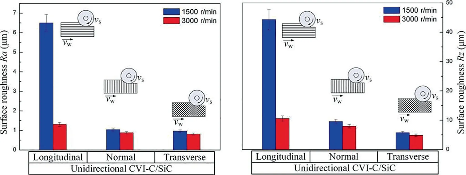
Fig. 21 Effect of fiber orientations on machined surface roughness.59
For various machining processes,the variation of machined surface roughness with machining parameters is widely discussed. The most consensus is that the machined surface roughness decreases with the increase of spindle speed(or cutting speed), increases with the increase of feed rate and grinding depth (or cutting depth).For grinding processes (including filing, drilling and milling by using diamond abrasive tools), the grinding parameters affect the material removal mechanism by changing the maximum undeformed chip thickness, which affects the machined surface roughness. For cutting processes, the cutting parameters affect the material removal mechanism by changing the cutting thickness, which affects the machined surface roughness. Since the specific cutting energy is the embodiment of material removal mechanism in energy, Chen et al.proposed that there was a negative correlation between the machined surface roughness and specific milling energy, as shown in Fig.22.But there are also some unusual conclusions.Du et al.conducted a grinding experiment on C/SiC composites, and the results showed that as the feed rate increased,both Sa and Sq decreased. And the influence of the maximum undeformed chip thickness on the surface roughness was not significant due to the fiber orientation. Adibi et al.and Esmaeiliet al.proposed that Ra decreased slightly as the grinding depth increased in MQL grinding of C/SiC composites,due to the reduction in grinding wheel wear.When drilling C/SiC composites by using PCD tools, Chen et al.found that if the cutting speed was too high,the tool would be unstable due to excessive load, resulting in a sharp increase in the machined surface roughness.When drilling C/SiC composites by using a diamond core drill, Ding et al.found that if the density of materials was low (the porosity was too high), the influence of machining parameters on surface roughness was unstable.
Besides the effects of material properties and machining parameters on the surface roughness, the effects of assisted machining parameters have also been discussed. For MQL,Adibi et al.,Esmaeili et al.and Qu et al.all proposed that in the grinding of C/SiC composites, compared with dry grinding, fluid grinding (wet grinding) and MQL grinding effectively reduced the machined surface roughness, due to good cooling and washing effect. It is worth noting that MQL grinding only uses a small amount of lubricating oil to obtain good comprehensive performance, with both effect and environmental protection. On this basis, Qu et al.discussed the effect of MQL parameters (nozzle direction, air pressure, oil flow rate, and nozzle distance) on the machined surface roughness. In addition, Qu et al.further proposed the application of NMQL in the grinding of C/SiC composites. The experimental results are shown in Fig. 23 indicated that the effectiveness of NMQL for reducing the machined surface roughness.
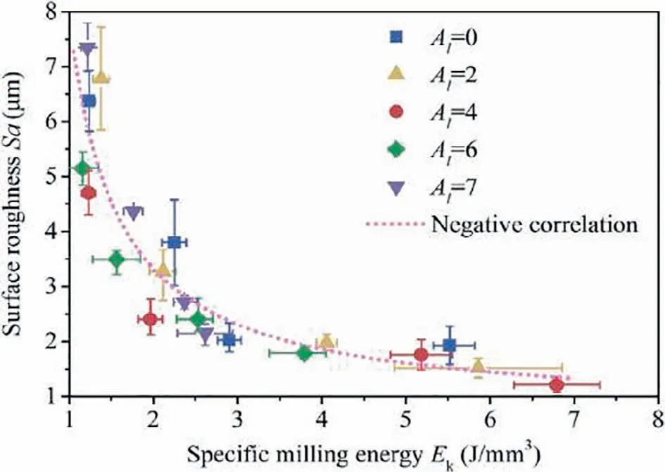
Fig. 22 Correlation between surface roughness and specific milling energy.100
For FRCMCs-SiC,UAM is recommended.Compared with CM, UAM effectively reduced the machined surface roughness, whether grinding(including filing,drillingand millingby using diamond abrasive tools) or cutting. However, Bertsche et al.found that the surface roughness of UAM was higher than that of CM in slot milling of SiC/SiC composites. But Bertsche also admitted that this conclusion may be inaccurate, due to the surface was evaluated by Ra and the influence of fiber orientation and measurement position.For grinding,the ultrasonic vibration of the abrasive makes the cutting path of the abrasive longer (as shown in Fig. 24), and the reduction of the maximum undeformed chip thickness results in the reduction of chips.Another point of view is that the ultrasonic vibration makes the contact between the abrasive and the workpiece from continuous to intermittent, which results in smaller chips.And Wang et al.proposed that ultrasonic vibration changed the fracture mode of carbon fibers,and the fracture of carbon fibers in the cutting plane was conducive to the reduction of roughness.For cutting, the high-frequency hammering effect of the cutting edge promotes the initiation and propagation of microcracks inside the carbon fiber, causing nano-scale brittle fracture of carbon fibers, which reduced the machined surface roughness.Furthermore, the effect of ultrasonic amplitude on the surface roughness has also been studied. In UAF experiments of C/SiC composites, Wang et al.found that Sz and Sq decreased with the increase of ultrasonic amplitude. In RUM experiments of C/SiC composites, Wang et al.proposed that when the spindle speed was low, the hole surface quality was better as the ultrasonic amplitude increased, But when the spindle speed was further increased, the increase in ultrasonic amplitude had no obvious benefit to the further improvement of the hole surface quality. The results of UAM of C/SiC composites by Chen et al.showed that Sa decreased with the increase of ultrasonic amplitude, but when the amplitude exceeded the threshold value of micro-scale brittle fracture of carbon fibers, the increase in amplitude instead increased Sa.
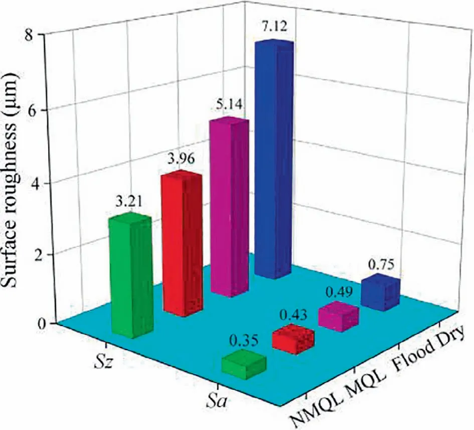
Fig. 23 Effect of lubrication conditions on machined surface roughness.70
There are few studies on LAM of FRCMCs-SiC.However,based on the LAM experiments of C/SiC composites,Erdenechimeg et al.proposed that LAM improved the machined surface quality, and as the preheating temperature increased,the surface roughness decreased.
4.2. Machining defects
The components of FRCMCs-SiC are complex, anisotropic,and heterogeneous. After removing the materials, various machining defects will be formed on the fiber, the SiC matrix,and the interface. Many scholars have also explored the machined surface defects,subsurface defects,and edge defects.
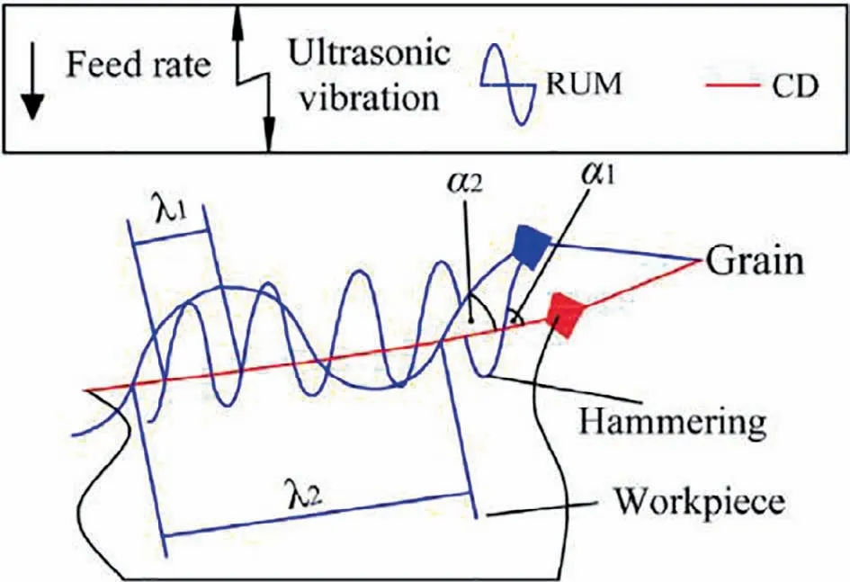
Fig. 24 Grain trajectories of RUM and CD.87
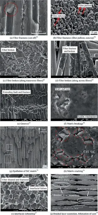
Fig. 25 Machining defects on machined surface of FRCMCs-SiC.
Researches on machined surface defects are the most.Zhang et al.first summarized that the machining defects of unidirectional C/SiC composites in grinding were the combination of matrix cracking, fiber fracture, and interfacial debonding. Liu et al.analyzed the grinding of 2D C/SiC composites, Zhang et al.analyzed the milling of 2.5D C/SiC composites and Hu et al.analyzed the milling of 2D Cf/SiC composites, the same conclusion was proposed. This conclusion is relatively preliminary, and this expression has been further expanded with the in-depth observation and analysis of the machined surface. Du et al.described machining defects in detail for three typical fiber orientations. Along longitudinal fibers, laminated fractures, shear fracture, and a compression fracture of carbon fibers, spallation of SiC matrix, and cracks in the SiC matrix were observed. Along transverse fibers,various fiber fractures and interfacial failures were observed.Along across fibers,grooves,fiber pull-out,and fiber broken were observed. Qu et al.thought that fiber fracture, matrix cracks, interfacial debonding and fiber wear were the basic forms of C/SiC composite damage, and proposed that changes in machining parameters would not cause changes in the material removal mechanism, but the proportion of different damage forms would be changed. As the grinding speed increased,the grinding length and vertical force of the single abrasive became smaller resulting in small cracks,which improved the quality of the machined surface. As the feed rate increased, the maximum undeformed chip thickness increased and more cracks were generated. As the grinding depth increased,the area of fiber wear decreased,but the interfacial debonding and fiber fractures increased. For the cutting of SiC/SiC composites, Diaz et al.proposed that the machining defects in the fiber-rich region were fiber fractures,fiber pulling out,fiber unpulling out and radial cracks of CVISiC, the machining defect in the matrix-rich region was SiC grains pulling out. Furthermore, Qu et al.proposed that the fiber fracture mode was affected by machining parameters,the sharpness of the abrasive, and the lubrication conditions.The extrusion and shearing of the abrasive particles led to long cracks and deep interfacial debonding.However,in MQL and NMQL grinding, the length and depth of matrix cracks and interfacial debonding were limited,and machining defects were reduced. Adibi et al.proposed that MQL grinding brought narrower scratches on the machined surface, more uniform surface, and better-machined surface quality. Wang et al.found that during conventional filing, carbon fibers were cut or pulled out by the abrasive,the matrix and fibers were separated, the carbon fiber circumferentially fractured without axial damage. But when UAF, carbon fibers had obvious scratches along the axial direction. Liu et al.believed that compared with conventional milling, UAM was beneficial to improve the matrix breakage,but the effect of improving fiber breakage was not obvious. Babbar et al.proposed that fiber pulling out was the main machining defect. When using PCD tools to drill 2D C/SiC composites, Zou et al.found that braided layer separation and bifurcation of yarn were also typical machining defects for this woven fiber bundle structure.Based on the above conclusions, in summary, the surface machining defects of FRCMCs-SiC included fiber fractures(cut off, crushing, pulling out, outcrop), fiber broken (fiber damage), grooves, and matrix breakage, spallation of SiC matrix, matrix cracks, interfacial debonding, braided layer separation and bifurcation of yarn.Fig.25 shows the images of these defects.

Fig. 26 Machined surface defects in the grinding of 3D needled Cf/SiC composites.83
Because FRCMCs-SiC is fiber-rich materials,carbon fibers have a large number of machining defects and has a great impact on surface quality,which should be focused on.Therefore, some studies have focused on the machining defects caused by material removal on carbon fibers. Ding et al.observed the machined surface of 3D needled C/SiC composites by grinding and proposed that 0°fibers and needled fibers have a lamellar brittle fracture, 90° fibers have brittle fracture and fiber pull out, which all caused pits on the machined surface,as shown in Fig.26.The size of the surface pits decreased with increasing grinding speed and increases with increasing feed rate and grinding depth.UAM effectively reduced the size and depth of lamellar brittle fracture, which has been verified in ultrasonic-assisted grindingand ultrasonic-assisted drilling.Chenproposed that C/SiC composite was a kind of fiber-rich material, and the material removal mechanism of carbon fibers directly determined the machined surface quality. The pits formed after brittle fracture of carbon fibers were the main machining defects on the machined surface.The change of machining parameters resulted in the transition of the material removal mechanism of carbon fibers.As shown in Fig.27,if carbon fibers occur nano-scale brittle fracture,the machined surface of composites is flat, but the machined surface of the carbon fiber is rough. If carbon fibers occur micro-scale brittle fracture (bending-induced fracture,compression-induced fracture, shear-induced fracture), the machined surface has pits, because the fractures of carbon fibers are not in the cutting plane and the fractures of carbon fiber are inclined. The high-frequency hammering of cutting edge caused by ultrasonic-assisted milling promoted the initiation and propagation of micro-cracks inside carbon fiber,and induced carbon fiber to be removed with nano-scale brittle fracture, thus effectively reducing the machined surface defects.
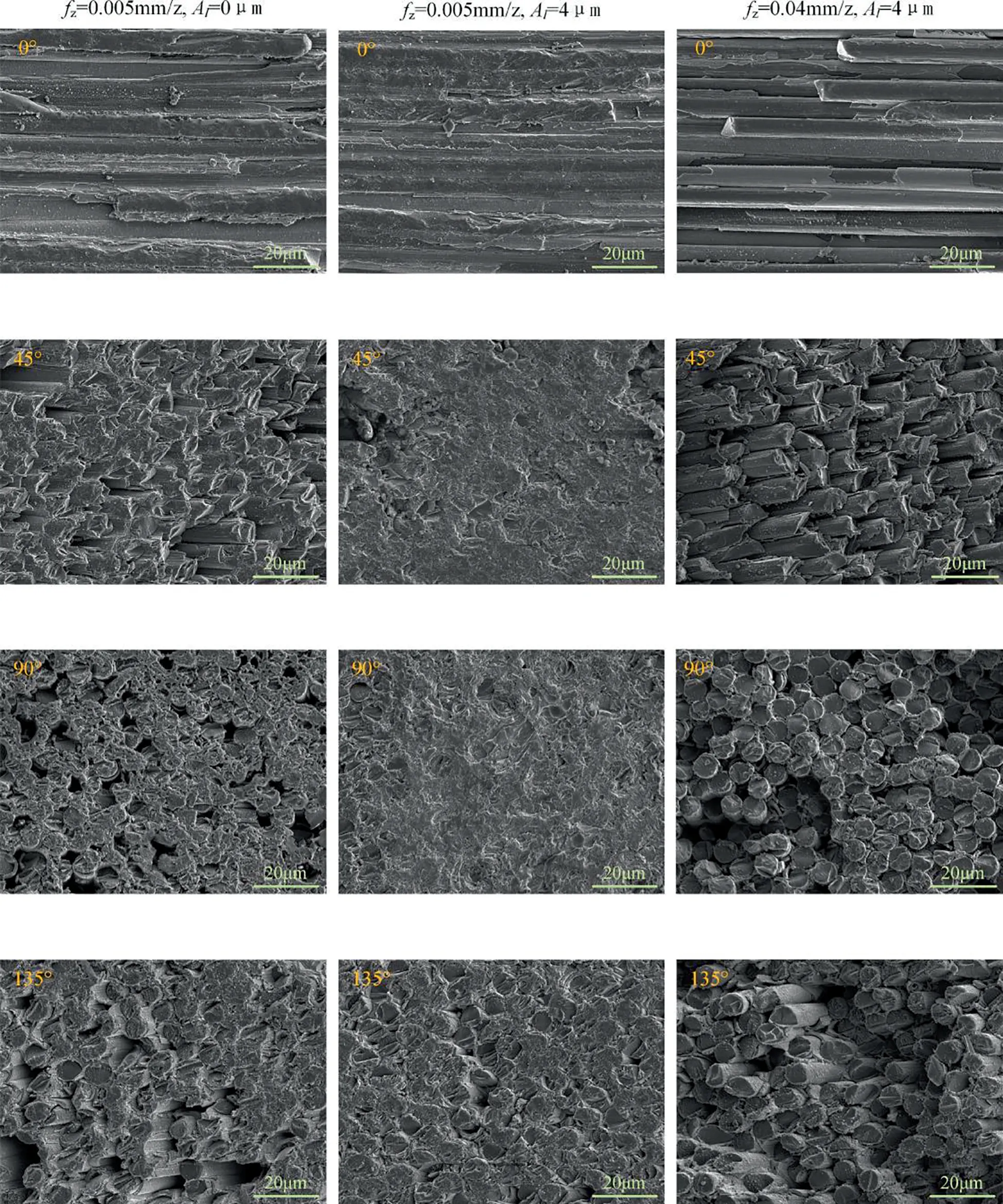
Fig. 27 Micro-morphology of machined surface in milling of 2D Cf/SiC composites.100
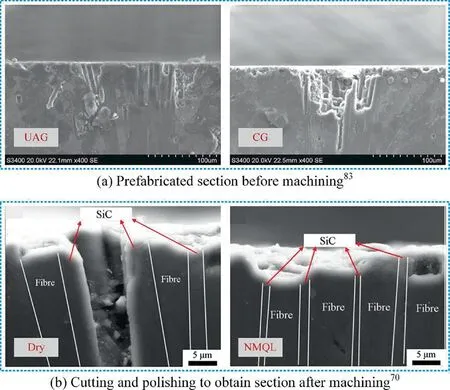
Fig. 28 Machining defects on machined subsurface of 2D Cf/SiC composites.
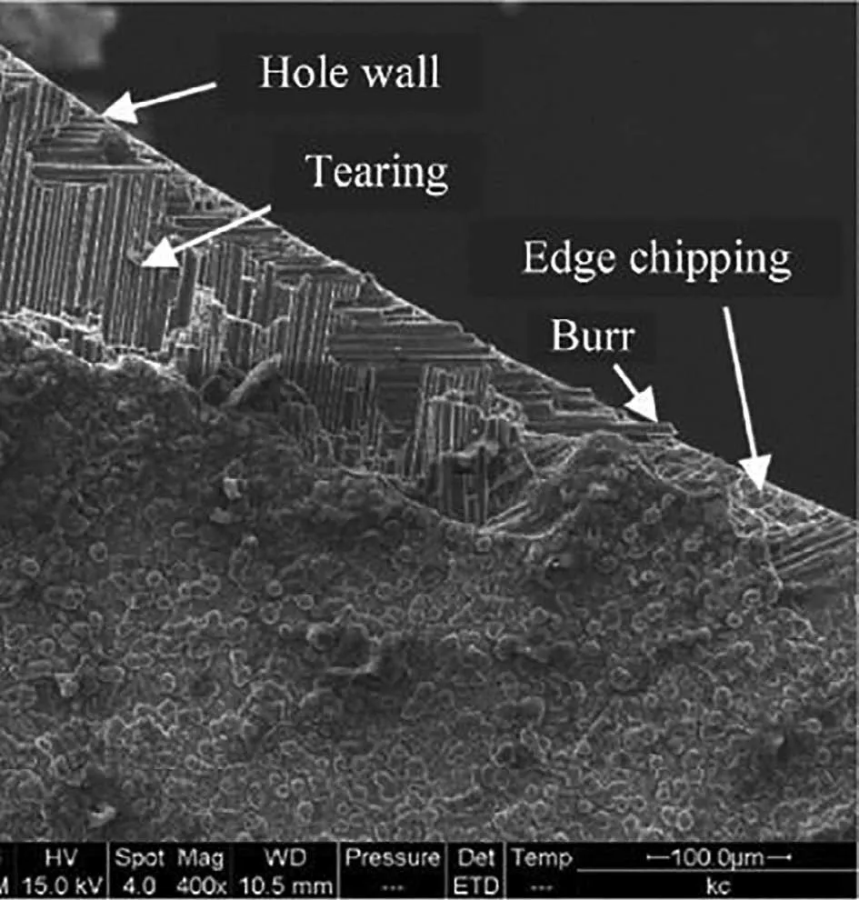
Fig. 29 Machining defects at hole exit of Cf/SiC composites.91
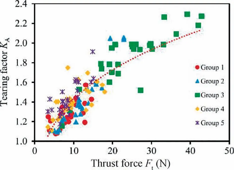
Fig. 30 Relationship between thrust force and tearing factor.88
Besides surface machining defects, subsurface machining defects are also an important component of machined surface quality. Surface machining defects are easy to observe, using an optical microscope or scanning electron microscope(SEM). But subsurface defects are not easy to observe. Sample preparation is a challenge. One of the methods is to cut the workpiece before machining, grind and polish the section,and then glue them together. After machining, separate them to observe the subsurface morphology. Ding et al.used this method to observe the subsurface defects of CG and UAG of C/SiC composites. The pits formed by the fracture of fibers and fiber bundles were the main defects, and UAG effectively reduced such defects, as shown in Fig. 28(a) and (b). If the combination of mechanical cutting and mechanical polishing is used, the mechanical damage during the sample preparation have a great impact on the subsurface machining defects and some of which may not be observed. Diaz et al.observed subsurface defects during micro-drilling of SiC/SiC composites and found that there were fiber fracture, fiber pull-out, and fiber unpull-out. Qu et al.focused on fiber pull-out and proposed that NMQL grinding had a good effect on reducing fiber pull-out, as shown in Fig. 27(c) and(d).
Some of the structures (such as through-hole and groove)produced by machining has edges. For these machining processes, machining defects of the edge has an important impact on the quality of parts. Hole machining is the most widely implemented process. The defects at the hole exit of FRCMCs-SiC has not been uniformly named. In some researches, delamination by directly referring to the defects of CFRP is used, and the delamination factor is used in the quantitative evaluation.And in some researches, hole exit defects are defined as tearing, and the tearing factor is used in the quantitative evaluation.In view of the variety of defects at the hole exit, including tearing, edge chipping, and burr (as shown in Fig. 29), the damage factor is used in the quantitative evaluation.The reason for the damage at the hole exit is that fibers deform under the action of the axial force due to the lack of support of the materials when the tool is fed close to the exit. Therefore, many studies have shown that the axial force is a direct factor affecting the hole exit defects.Feng et al.obtained the positive correlation diagram between the tearing factor and the thrust force as shown in Fig. 30 through experiments. Therefore, various variables affect the quality of the hole exit by changing the thrust force in machining. Increasing the spindle speed and reducing the feed rate can reduce the defects of the hole exit.In addition, compared with the CM, the effectiveness of RUM to reduce the hole exit defects has been widely recognized, and with the increase of amplitude,the exit quality is improved. Furthermore, Wang et al.designed a new compound step-taper drill, which effectively reduced the tearing due to the reprocessing effect. According to the difference in color and shape between the hole exit defects and the composites,Zou et al.calculated the 2D damage factor based on the image processing technology(as shown in Fig. 31), which improved the efficiency of hole exit quality evaluation.
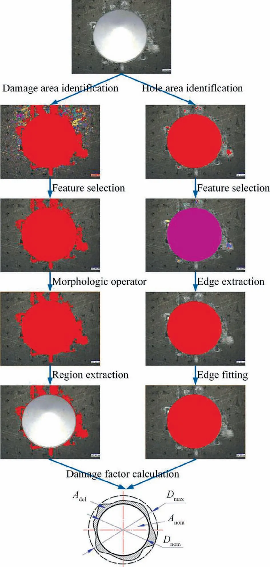
Fig. 31 Calculation of 2D damage factors based on image processing technology.77
The machining defects to the edge during slot milling are also worthy of attention. Hu et al.proposed that the edge defects in slot milling of C/SiC composites include fiber protrusion, surface damage, and both of them (as shown in Fig. 32). The damage width and count were used to evaluate the damage quantitatively.The results showed that the surface damage was far more than the fiber protrusion.And the damage increased with the feed rate increases.
4.3. Residual stress
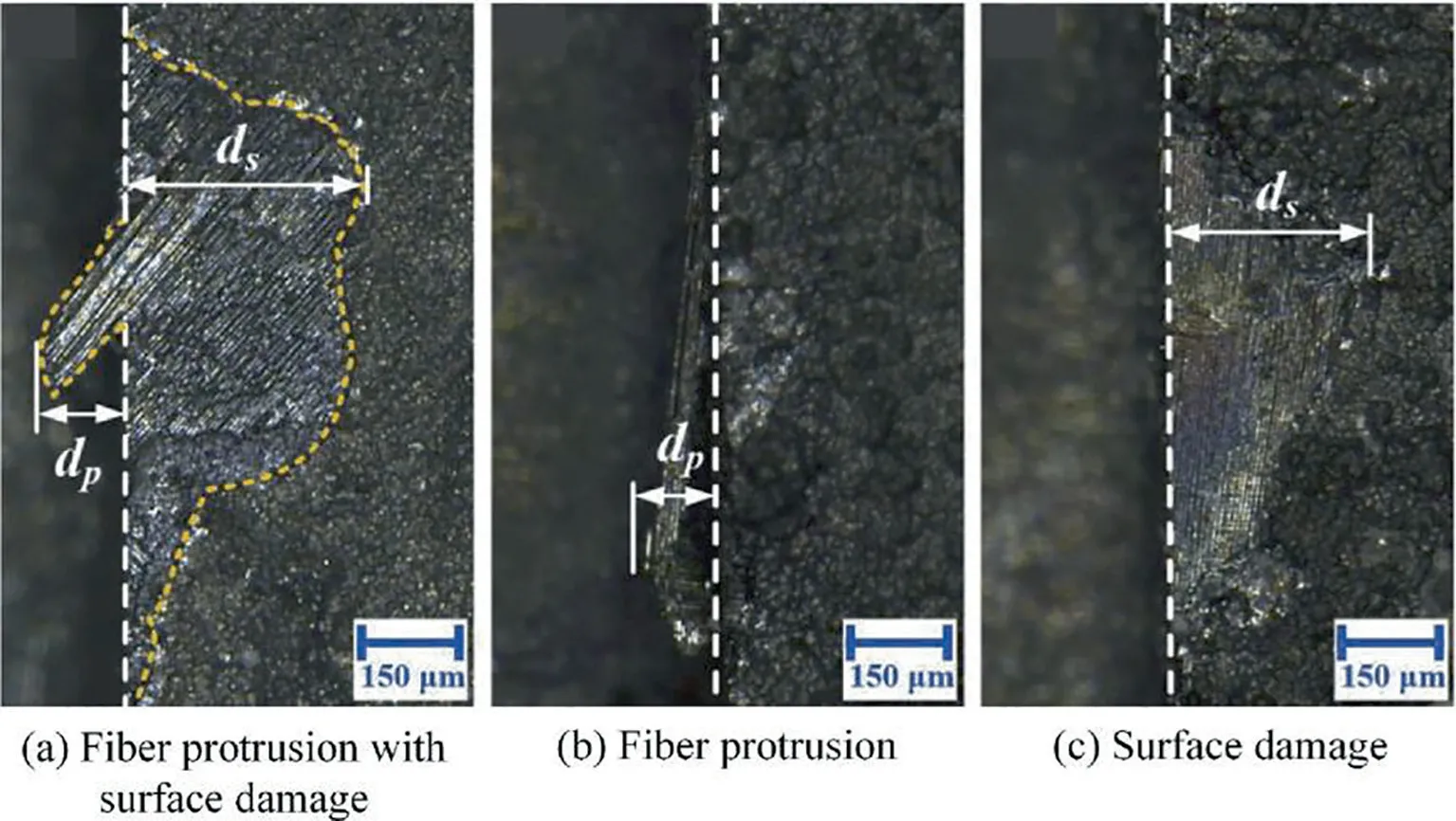
Fig. 32 Three main forms of machined defects of side edges.75
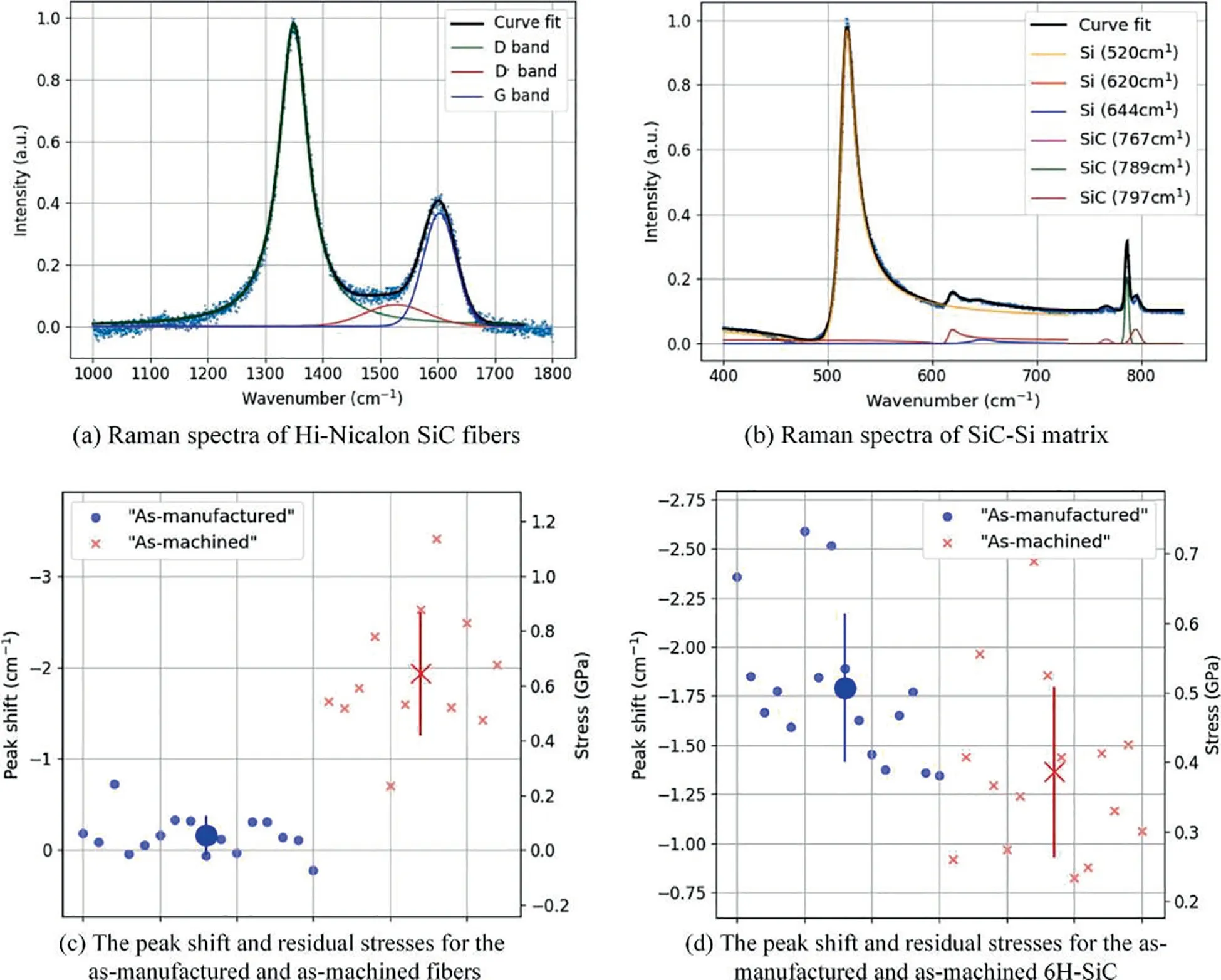
Fig. 33 Residual stress analysis based on Raman spectroscopy.54
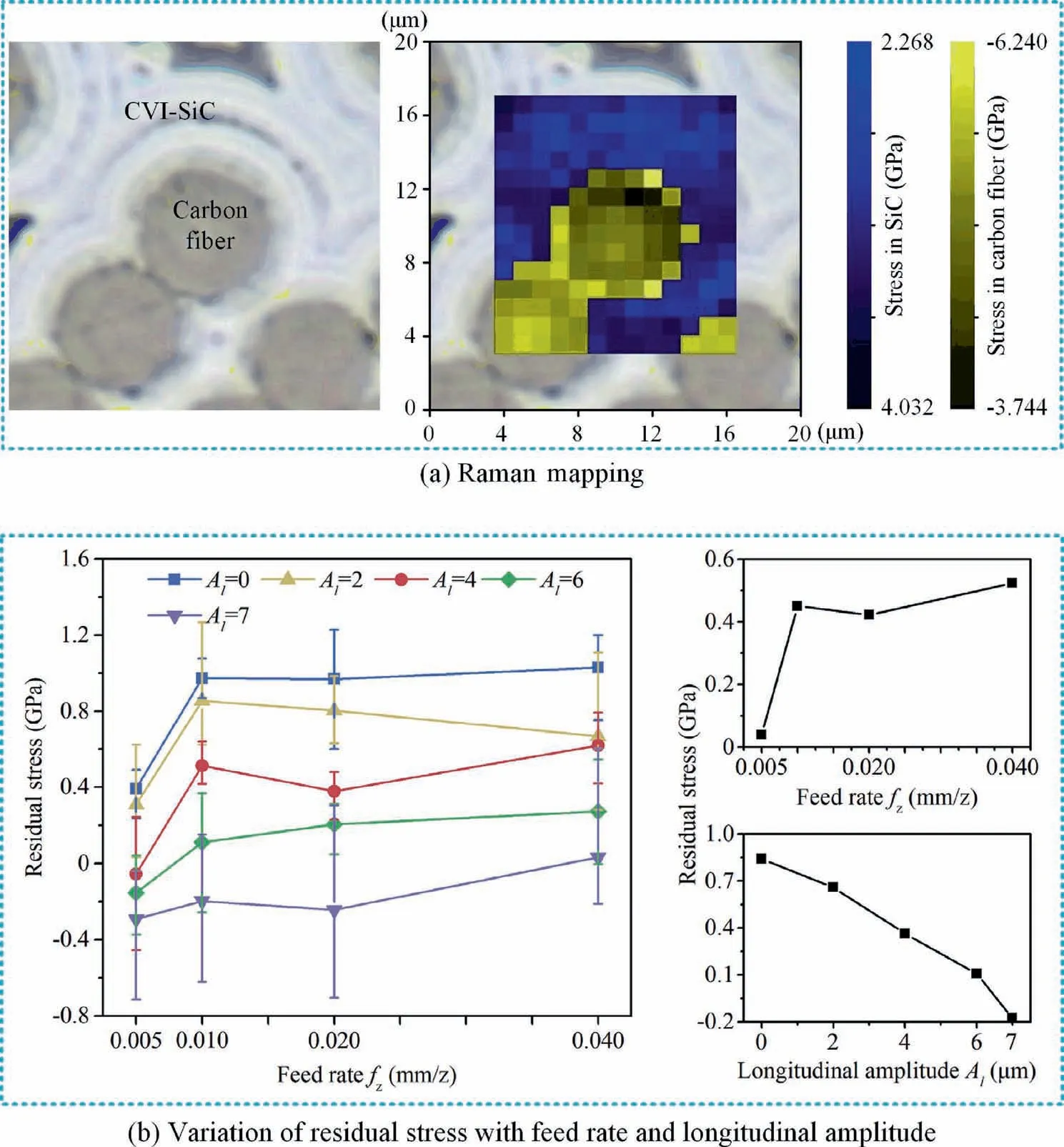
Fig. 34 Effect of feed rate and ultrasonic amplitude on residual stress. 100
Residual stress is an important index to evaluate the machined surface quality. However, compared with metal materials, the impact of the residual stress on the machined surface on service performance and service life of FRCMCs-SiC parts has not been clearly concluded.Therefore,there are only a few preliminary explorations of the residual stress on the machined surface of FRCMCs-SiC. Azarhoushang et al.measured the residual stress of the machined surface based on X-ray diffraction during the evaluation of the performance of the segmented grinding wheel in the grinding of C/SiC composites.The results indicated that C/SiC composites have tensile residual stress on machined surface. The application of segmented grinding wheels was beneficial to reduce residual stress because the initiation and propagation of a large number of microcracks during material removal had a stress relief effect. Diaz et al.characterized the surface stress and chemical composition of SiC/SiC composites by micro-Raman spectroscopy and discussed the sources of the residual stress of different phases and the relationship between the fracture behavior of the material and the residual stress. Fig.33 shows the residual stress measured based on Raman spectroscopy.The peak position of the Raman spectrum of the material will shift under the action of stress,and the peak shift value has a certain mapping with the stress. Therefore, the Raman spectrum of the machined surface is obtained by using a micro-Raman spectrometer, and the residual stress of the machined surface can be measured by extracting the peak displacement and converting according to the formula. Chen et al.further adopted the Raman Mapping method(as shown in Fig.34(a))to obtain the Raman spectrum of the measured surface and converted it into a residual stress distribution map based on the peak shift.Based on this method, the residual stress of the machined surface in milling of C/SiC composites was measured and analyzed. And for C/SiC composites, the effectiveness of UAM to reduce the tensile residual stress was confirmed(Fig.34(b)).
5. Conclusions
FRCMCs-SiC is an excellent high-temperature material and friction material,which has promising applications in the aerospace,energy,transportation,and other industries.Machining is indispensable in the preparation of parts,and the machining quality has a significant impact on the service performance and service life of parts. Many scholars have actively explored the material removal mechanism, machining processes, and surface integrity, and achieved some results. Based on the literature survey, the following conclusions are drawn:
· The material removal mechanism of FRCMCs-SiC in machining can be broadly summarized as brittle fracture(including matrix crushing, interfacial debonding, fiber fracture). Furthermore, the brittle fracture mechanism of the fiber is worth subdividing into nano-scale brittle fracture and micro-scale brittle fracture.The weak fiber-matrix interface is beneficial to improve the toughness of the material, but it is a challenge to avoid interface defects during machining.An in-depth exploration of the material removal mechanism can facilitate understanding machined surface generation mechanisms and provide ideas for avoiding machining defects.
· For machining FRCMCs-SiC, the processes of CM, UAM and LAM have their own advantages.Based on preliminary experimental exploration, compared to CM, UAM can reduce the force by 7.4-%,reduce the surface roughness by 12-30%, improve machining efficiency by 10-480%, and reduce tool wear by 28.06-36%,LAM can reduce the force by 40-40.7%,reduce the surface roughness by about 33.8%,andincreasethetoollifeby3.8times.Overall,UAMhasobvious advantages in improving machining efficiency,and LAM has obvious advantages in improving tool life.
· Considering the extreme service environment,the machining quality of FRCMCs-SiC parts is the most concerned in machining. The effects of machining parameters, material properties (fiber orientation, machining direction, material density),and tool parameters onthe roughness are widely discussed. Besides, a great variety of machining defects is an important feature of FRCMCs-SiC machining. Fiber fractures (cut off, crushing, pulling out, outcrop), fiber broken(fiber damage),grooves,and matrix breakage,spallation of SiC matrix, matrix cracks, interfacial debonding, braided layer separation and bifurcation of yarn are all observed,and there are also edge chipping,burr and tearing at the structural edge.Because the influence of the residual stress of the machined surface on the service performance of FRCMCs-SiC parts is not clear,there are few related researches.
6. Prospective outlook
Researches on the machining of FRCMCs-SiC is preliminary but has been concerned. With the further expansion of the application of FRCMCs-SiC, the requirements for manufacturing will be further increased. For machining, more indepth and systematic researches are urgently needed.
· Up to now, the removal mechanism and damage behavior of FRCMCs-SiC under the assistance of various energy fields are still unknown,so it is necessary to carry out mechanism experiments for different assisted machining processes, which is of great significance to deeply understand the mechanism and optimization direction of assisted machining processes. More scientifically, it is also expected to establish theoretical or numerical models to describe material removal mechanisms.
· For machining processes,improving conventional processes and designing production equipment suitable for new processes are significant issues, and there is an urgent need to develop machining tools (such as cutting-edge tools and abrasive tools) suitable for FRCMCs-SiC.
· The quantitative evaluation indexes of machined surface quality are also urgently needed to be determined. At present, the evaluation of FRCMCs-SiC machined surface is still using the single evaluation indexes of metal materials or CFRP, which is obviously insufficient. In establishing a machining quality evaluation system for FRCMCs-SiC,the mapping between the surface integrity indexes (such as roughness, damage layer thickness, defects, etc.) and the service performance indexes (such as mechanical properties, fatigue properties, bonding properties with the environmental thermal barrier coating, etc.) is also worth considering.
Declaration of Competing Interest
The authors declare that they have no known competing financial interests or personal relationships that could have appeared to influence the work reported in this paper.
Acknowledgement
This study was supported by the National Natural Science Foundation of China (No. 51975368).
 CHINESE JOURNAL OF AERONAUTICS2021年4期
- CHINESE JOURNAL OF AERONAUTICS的其它文章
- Time delay compensation in lateral-directional flight control systems at high angles of attack
- Dual stability enhancement mechanisms of axial-slot casing treatment in a high-speed mixed-flow compressor with various tip clearances
- Development cost prediction of general aviation aircraft using combined estimation technique
- Improvement on shaped-hole film cooling effectiveness by integrating upstream sand-dune-shaped ramps
- Modeling and parameter identification of linear time-varying systems based on adaptive chirplet transform under random excitation
- An experimental method to obtain the hard alpha anomaly distribution for titanium alloy aeroengine disks
