Time delay compensation in lateral-directional flight control systems at high angles of attack
Lin SHEN, Da HUANG, Genxing WU
Key Laboratory of Unsteady Aerodynamics and Flow Control, Ministry of Industry and Information Technology, Nanjing University of Aeronautics and Astronautics, Nanjing 210016, China
KEYWORDS Adaptive control;Flying quality;High angles of attack;Time delay;Yaw-roll coupling
Abstract The previous studies of time delay compensation in flight control systems are all based on the conventional aerodynamic derivative model and conducted in longitudinal motions at low angles of attack. In this investigation, the effects of time delay on the lateral-directional stability augmentation system in high-α regime are discussed based on the ˙β model, which is proposed in our previous work and proved as a more accurate aerodynamic model to reveal the lateraldirectional unsteady aerodynamic characteristics at high angles of attack. Both the ˙β model and the quasi-steady model are used for simulating the effects of time delay on the flying qualities in high-α maneuvers. The comparison between the simulation results shows that the flying qualities are much more sensitive to the mismatch of feedback gains than the state errors caused by time delay. Then a typical adaptive controller based on the conventional dynamic derivative model and a gain-prediction compensator based on ˙β model are designed to address the time delay in different maneuvers. The simulation results show that the gain-prediction compensator is much simpler and more efficient at high angles of attack. Finally, the gain-prediction compensator is combined with a linearized ˙β model reference adaptive controller to compensate the adverse effects of very large time delay, which exhibits excellent performance when addressing the extreme conditions at high angles of attack.
1. Introduction
With the use of fly-by-wire flight control system, the handing capabilities and performance of a modern aircraft are significantly enhanced. Unfortunately, these improved capabilities have not evolved without cost. One of the major problems related to the electronic control system is the introduction of additional time delay which may degrade the flying qualities,especially for a combat aircraft.Based on plenty of flight tests,100 ms has been established as the allowable maximum delay for a fighter to satisfy Level 1 flying qualities in military specification.Level 2 and Level 3 upper limits are 200 ms and 250 ms, respectively.
The majority of the total time delay of a modern fly-by-wire control system is not produced by the hardware (such as sensor,actuator,filter,etc)but caused by the cascading of numerous dynamic elements employed in the complex system.With the increasing complex of the control architecture, the allowable maximum delay has been a great challenge for the designers of flight control system. Up to now, there is as yet no effective method to address large time delay in engineering applications of aircraft.Usually,the requirement of total time delay has to be met from the aspect of hardware,for instance,using a component with better performance or eliminating a unit which seems not so ‘‘indispensable”.However, this approach is of limited effect and difficult, as the performance of each component cannot be improved limitlessly and most of the elements are exactly indispensable.And most of all,this part of time delay is not the substantial obstacle.
In recent years, some works in the literature present controller designs that address the time delay in the flight control system according to advanced adaptive control theory,such as Smith predictor integrated with adaptive controllers,observer-based adaptive compensators,Hcontrollers,adaptive posicast controllers,robust adaptive controllers,and some other adaptive controllers.In these investigations,the degradation of flying qualities is considered as a result of state errors in the Stability Augmentation System(SAS) caused by time delay. Thus the error between the real flight parameters and the output of a reference model is corrected as much as possible by the adaptive controller, so that the effects of time delay can be reduced.However,the adaptive control approach of addressing time delay is not mature yet,and thus there are still some significant roadblocks for the implementation on an aircraft. Firstly, the total time delay τ should be known and constantin most of the current studies. Although some compensators of time-varying delay have been proposed, the time delay margin is discussed about the‘‘stability” rather than ‘‘flying qualities”.In other words,for a time-varying delay compensator,the degradation of flight qualities is acceptable.It seemingly deviates from the original intention of delay compensation. Secondly, in the previous simulation studies, the flying qualities are not sensitive to the values of time delay. The values of τ at which the adverse effects can be observed are usually several or even dozens of times larger than the allowable delay,and the cause of this discrepancy has not been analyzed in detail. In addition, the current studies of time delay compensation are all based on the conventional aerodynamic derivatives and conducted in longitudinal motions at low angles of attack, and they have not been extended to high angles of attack and sideslip conditions.Thus, the compensation of time delay in the lateraldirectional SAS at high angles of attack is of theoretical and practical importance.
This is a follow-up study of our previous works.Previously,yaw-roll coupled wind tunnel tests were conductedto reveal the effects of yaw-roll coupling ratio on the unsteady aerodynamic characteristics at high angles of attack. Then a ˙β model was proposedbased on the yaw-roll coupled experimental data, and demonstrated a higher precision than the conventional aerodynamic derivative method. Further, the ˙β model was applied to flight dynamics analysisand control laws design,which cannot be achieved by most of the unsteady aerodynamic models proposed in the past decades.
In this investigation, the ˙β model is used for the study of time delay compensation in lateral-directional motions at high angles of attack.Firstly,both the ˙β model and the quasi-steady model(an aerodynamic model based on the conventional aerodynamic derivatives and rotation rate derivatives)are used for time delay simulations.The simulation results are compared to reveal the major inducement of flying qualities degraded by the time delay.Then a typical Adaptive Controller(AC)based on the conventional aerodynamic derivative method and a Gain-Prediction Compensator (GPC) based on ˙β model are presented for time delay compensation.The performance of these two approaches is examined and compared in different maneuvers at high angles of attack. Finally, an extreme condition is discussed by combining the GPC with Model Reference Adaptive Controller (MRAC) to address a very large time delay at high angles of attack,by using the linearized ˙β model as a reference model. Thus far, a whole set of processes from the aspects of experimental method, aerodynamic modeling, flight simulation, flight dynamics analysis, control laws design and time delay compensation are completed to apply the largeamplitude oscillated experimental data to engineering practice.
2. Preliminaries and problem description
2.1. Description of aerodynamic models
2.1.1. ˙β Model
In our previous work, the lateral-directional unsteady aerodynamic characteristics of a typical fighter configuration were investigated in the yaw-roll coupled motions at high angles of attack. A parameter ‘‘coupling ratio η” (η = |r/p |) is used as an indicator of the degree of yaw-roll coupling, where r and p are the yaw rate and roll rate respectively. The main physical parameters of the test model, experimental details and results can be found in Ref. 21. The experimental results show that the dynamic damping characteristics of rolling and yawing moments drastically varied with coupling ratios at high angles of attack,which cannot be reflected by the conventional aerodynamic derivative method. Thus a ˙β model was proposed:

where i=l,n; Cis the rolling moment coefficient; Cis the yawing moment coefficient; Care the static aerodynamic coefficients with modeling parameters of angle of attack α and sideslip angle β; ΔCare the aerodynamic coefficients produced by time rate of sideslip angle ˙β, with modeling parameters of α, β, ˙β and η, and the sample data are obtained from the yaw-roll coupled tests; ΔCare the aerodynamic coefficients produced by ω(angular rate around velocity axis),with modeling parameters of α,β and ω,and the sample data are obtained from the rotary balance tests.The modeling principle was detailed in Ref. 22. Different from the previous unsteady aerodynamic models, the ˙β model can be locally linearized to a similar form as the conventional dynamic derivative model:
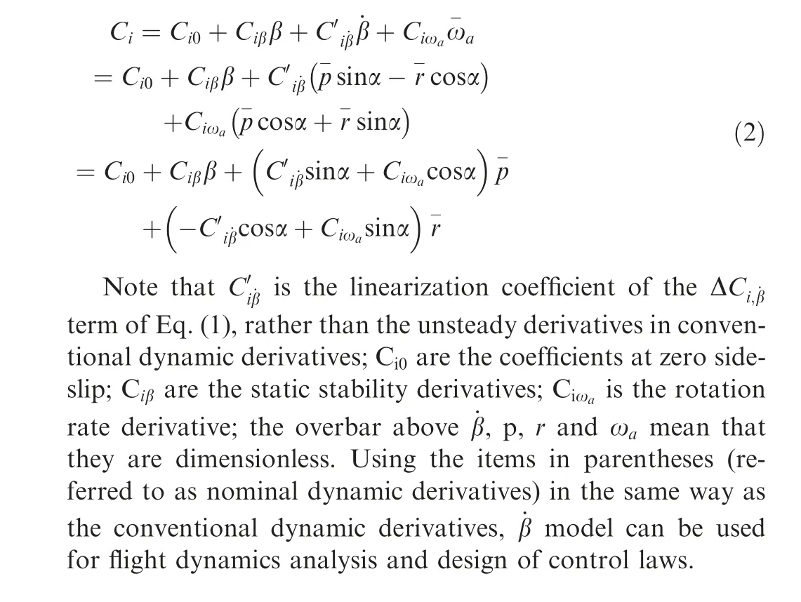
2.1.2. Conventional aerodynamic derivative method
Up to now, the studies of time delay in flight control systems are all based on the conventional aerodynamic derivative method. As the current studies are still remained in small-α regime, the most classical method, named dynamic derivative model, is used:
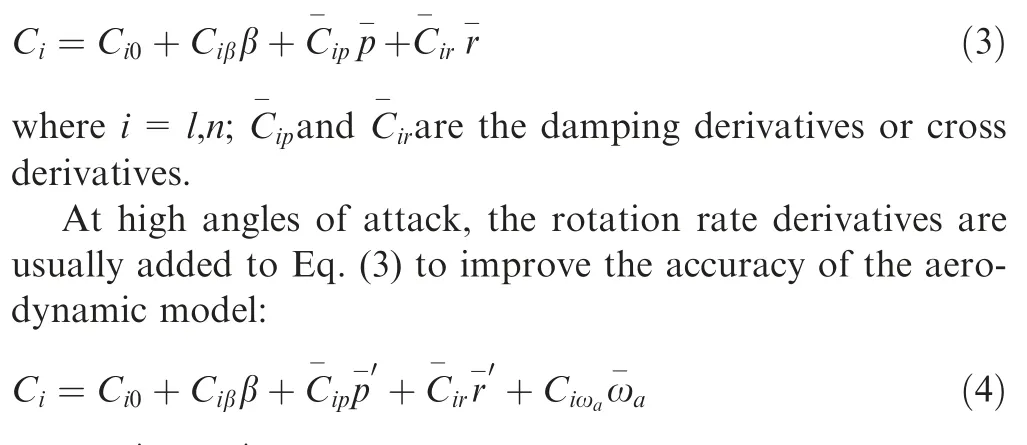

In the following sections, the flight dynamic analysis and control law design with respect to conventional aerodynamic derivative method are all based on the dynamic derivative model. The aerodynamic loads in the simulations with respect to conventional aerodynamic derivative method are produced by the quasi-steady model.
2.2. Departure characteristics and stability augmentation
For the investigated aircraft, the departure resistance will lose in partial region of the coupling ratio when the angle of attack is higher than 35°.This special departure characteristics can be accurately reflected by the linearized ˙β model but not the conventional aerodynamic derivative method. The details are discussed in Ref. 23.
Table 1 shows an example at α=40. The lateraldirectional short-period eigenvalues of open-loop system are calculated by both the ˙β model and conventional aerodynamic derivatives (The yawing motion is expressed as η=10).

2.3. SAS with time delay
In the closed-loop conditions,the standard state space form of the lateral-directional motion equations is expressed as
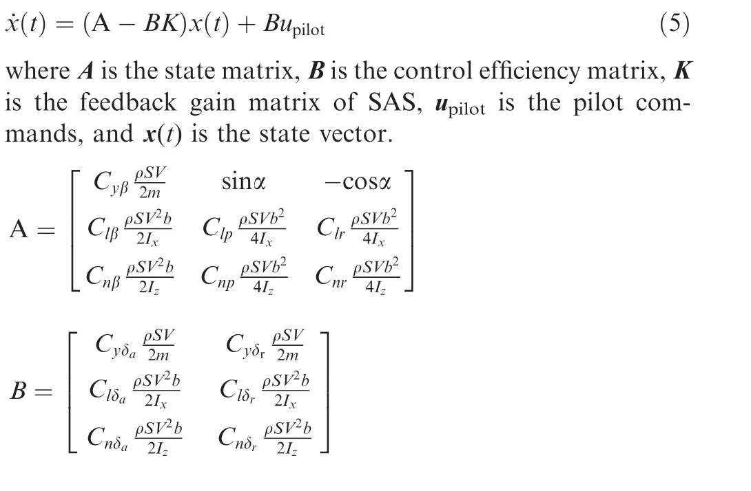
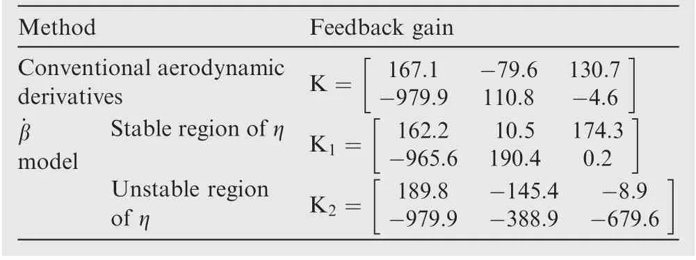
Table 2 Feedback gain matrices calculated by different methods (α=40°).

Table 1 Short-period eigenvalues of open-loop system at α=40°.

where m is the mass of aircraft;ρ is the atmospheric density;S is the wing area; b is the wing span; V is the total velocity; Iand Iare the moments of inertia; C, Cand Care the control efficiencies of aileron;C,Cand Care the control efficiencies of rudder.
The control commands of stability augmentation given by the SAS are

When the time delay is introduced, the commands of SAS are changed:

Actually, the time delay also exists in the pilot commands,and may lead to the Pilot Induced Oscillation(PIO)in specific flight task.However,it is another issue in the design of flight control systems. In this investigation, the pilot commands are simply set as square signals to perform a maneuver. The time delay in the pilot commands has no effects on the flying qualities. Thus the delay of the pilot commands is ignored, so that the simulation results of different total time delay can be compared directly.
3. Inducement of flying qualities degraded by time delay
In the previous studies, the effects of time delay on the flying qualities are generally considered as the results of the mismatch between the state parameters of the controlled plant and SAS:

However, the simulation results in these studies show that the flying qualities are not very sensitive to the values of time delay. The values of τ at which the adverse effects can be observed are usually several or even dozens of times larger than the allowable delay.
In this section, both the ˙β model and the quasi-steady model are used for the simulation of steady turning with different time delays at α=40. The simulation results are compared to clarify the main inducement of time delay effects on the flying qualities.
The simulation is started with a straight and level flight at α=40. At t=30 s, the pilot command of δ=-15is inputted, and the aircraft enters into a steady turning. At t=140 s, the pilot command is cancelled, and the aircraft is recovered to the straight and level flight.
3.1. Linear aerodynamic model with fixed-gain SAS
In the previous studies based on the conventional aerodynamic derivative methods, the simulation conditions are usually simplified. Since both the value and variation of α are small in these studies, the feedback gains are commonly considered as fixed. Similar simulations are conducted with τ=0 ms,100 ms, 200 ms and 300 ms. As the angle of attack is up to 40°, the quasi-steady model is used to produce the aerodynamic loads in the simulations. The simulations results are shown in Fig.1.As illustrated,the difference between different time delay cases is negligibly small. The simulation results of τ=100 ms coincide exactly with the results of τ=0 ms.With the further increase of time delay, the amplitudes of the state parameters (β, p and r) are slightly increasing at the entry and recovery stages, but not much. Even at τ=300 ms, the effects of time delay are far from the degradation of flying qualities. These simulation results are consistent with most of the previous studies at low angles of attack, as the simulation conditions are similar: a linearized aerodynamic model and a SAS with fixed-gain.
3.2. Non-linear aerodynamic model with gain-scheduled SAS
However, in a real flying environment, the parameters in control systems affected by the time delay are not only the state vector, but also the feedback gain matrices. As a typical gain-scheduled controller,the SAS designed by ˙β model is then used to clarify the main influence factors of time delay on the flying qualities. For the investigated aircraft, the lateraldirectional departure resistance at such a high angle of attack is not constant but varies with coupling ratio, as shown in Table 1. Two feedback gain matrices are obtained according to the stable and unstable regions respectively. At α=40,the unstable region of coupling ratios is [0.4, 1.8]. Due to the impact of τ, two items in the control commands of stability augmentation are changed:

Fig. 2 shows the simulation results with τ=0 ms, 80 ms,100 ms and 300 ms. The aerodynamic loads in the simulations are produced by ˙β model,and are closer to the real flight than those produced by the quasi-steady model.In the simulation of τ=80 ms,the results are almost the same as that of τ=0 ms.When the time delay increases to 100 ms, the oscillation of sideslip angle is observed.It is obvious that the flying qualities have been affected by such a small time delay, and consistent with the conclusions of the flight testsbased on which the allowable time delay in the design specification of combat aircraft was determined.
With the further increase of time delay,the amplitude of the oscillation is increasing.At τ=300 ms,the deflection of rudder issaturated,andthedeflectionofaileron variessharply.Furthermore,when the time delay is larger than 100 ms,the period of turning(indicated by the heading angle)increases with the total delay. The flight trajectories of τ=0 ms and 300 ms are illustratedinFig.3.Withalargertimedelay,althoughtheoscillations of state parameters and control surfaces are dramatic,the trajectory has not been divergent.When the pilot commands are cancelled, the fighter can be recovered to the straight and level flight quickly.Obviously,the issue of the flying quality degradationcausedbytimedelayisdifferentfromtheproblemofcontrollability caused by instability.However,in the previous studies,especially in the time delay margin analysis of an adaptive controller,these two problems are often ambiguous and the oscillations are usually considered as acceptable.
Then a simple approach is proposed to demonstrate the eigenvalues distribution of the closed-loop system during the maneuvers. As the control deflections are all conducted by the linear feedback gains of SAS, an imaginary feedback gain matrix Kis assumed without delay:
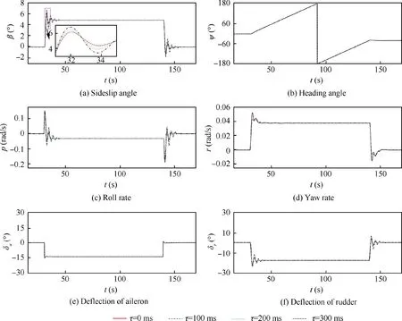
Fig. 1 Time delay in steady turning at α=40° (quasi-steady model).
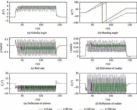
Fig. 2 Time delay in steady turning at α=40° (˙β model).

Fig. 3 Trajectory of steady turning at α=40° (˙β model).
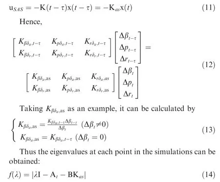
where I is a unit matrix, and Ais the real-time state matrix switched according to coupling ratio.
Fig. 4 shows the distribution of the short-period eigenvalues in main part of the maneuver(from 20 s to 160 s)simulated by ˙β model with τ=300 ms. The sampling interval is set as 20 ms, and thus there are 7000 groups of poles (three in each group) in total. The color bar indicates the amount of poles distributing in per unit area around each eigenvalue. The unit area is defined as the area of a rectangle with the length of 0.04 along real-axis and width of 0.04 along imaginary-axis.
Because of the time delay, the eigenvalues distribute dispersedly,and lots of them are far away from the designed locations. Furthermore, an appreciable number of these characteristic roots locate in the right-half plane. Obviously,the flying qualities during the maneuvers with time delay are degraded.
3.3. Non-linear aerodynamic model with fixed-gain SAS
In the case shown in Fig. 1, the feedback gains and aerodynamic loads are both obtained from the linearized aerodynamic model. But in the case of ˙β model, the aerodynamic loads in the simulations are produced by the non-linear form of Eq.(1)and the feedback gains are designed by the linearized form of Eq.(2).In order to confirm that the degradation of flying qualities is mainly caused by the mismatch of the feedback gains rather than the errors introduced by the linearization in the design of SAS, a further study is conducted. The sample data in the unstable region of coupling ratio together with the corresponding feedback gains are deleted from ˙β model,and other conditions are the same as those in Fig. 2. Thus the simulation environment is simplified as a non-linear aerodynamic model with a fixed-gain SAS.
The simulation results of sideslip angle with τ=0 ms and 300 ms are illustrated in Fig. 5. Similar to the results shown in Fig. 1, the flying qualities are insensitive to the time delay.The distribution of characteristic roots (from 20 s to 160 s) is also illustrated in Fig. 6. The vast majority of the eigenvalues are located around the designed points. Although some eigenvalues are shifted due to the errors of state parameters, the number of them is negligible. Thus the flying qualities of the whole maneuver have not been affected obviously.
It is clear that within a limited time delay,the errors of state parameters will not lead to the degradation of flying qualities.By contrast, the mismatch of the feedback gains due to the time delay is the main cause of this problem,which is neglected in the previous studies.
4. Compensation of time delay
4.1. Adaptive controller
4.1.1. Design of control laws
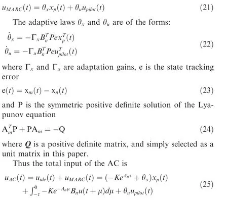
In the adaptive control methods,the adverse effects of the time delay are often considered as equivalent to the effects of reference model uncertainty, since both of them will introduce the errors of state parameters in the SAS.In this section,a typical adaptive control approach based on the conventional aerodynamic derivative method consisting of state predictorand MRACis first exhibited.
For a time-delay system without pilot input, the controlled plant with state space description can be written as
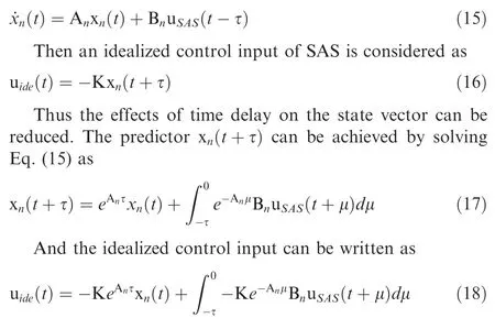
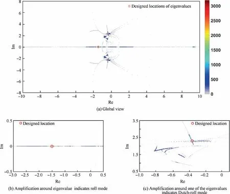
Fig. 4 Eigenvalues distribution in simulation of ˙β model (τ=300 ms).
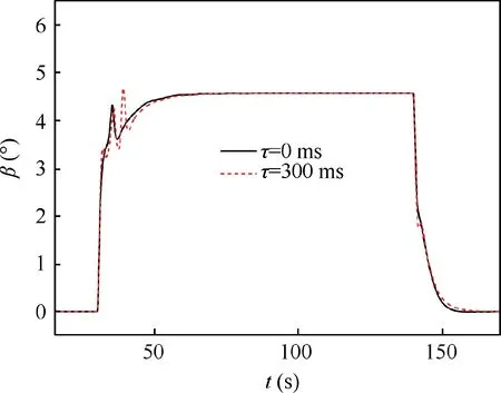
Fig. 5 Simulation of steady turning at α=40° by removing unstable data from ˙β model.
Then an adaptive control part is further introduced to eliminate the errors between the reference model and controlled plant.
Define the reference model as

4.1.2. Compensation effectiveness of AC
The adaptive controller is then used for the compensation of time delay. The maneuver is still the steady turning atα=40. Firstly, the aerodynamic loads are calculated by the quasi-steady model. Thus an additional uncertainty is introduced due to the item of rotation rate derivative which is not included in the reference model (dynamic derivative model). The simulation results of sideslip angle are illustrated in Fig. 7, with a total time delay of 300 ms.
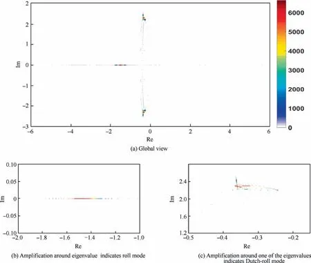
Fig. 6 Eigenvalues distribution in simulation of ˙β model without unstable data (τ=300 ms).
In the previous studies of time delay compensation based on adaptive control approach, the control performance is all evaluated by comparing the controlled states with the tracking signal. According to such a standard, the AC shows perfect performance. The response is pretty fast without oscillation.
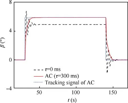
Fig. 7 Adaptive controller in steady turning (τ=300 ms).
However,as a result of model tracking,the sideslip angle of AC in the turning stage is different from that of no delay case,due to the difference between the reference model (dynamic derivative model) and the controlled plant (quasi-steady model). Theoretically, the flying qualities in the AC case should be close to the reference model whose eigenvalues are chosen according to the level 1 requirements. However, the overshoot and settling time of the response show that the pair of complex conjugate roots which indicate Dutch-roll mode seem more close to the real axis, and the absolute value of the negative real root (real part of the complex root) is larger.Unfortunately, there is a lack of tools available to analyze the flying qualities in the flight with adaptive control.As the control commands are not completely given by the linear feedback gains of SAS, the method of Eq. (12) cannot be used to show the eigenvalues distribution, either.
Fig. 8 shows the flight trajectories in the simulations of τ=300 ms with and without AC. Obviously, the flight mode has been completely changed. Hence in the adaptive control approach for the compensation of time delay, the flight states have not been corrected to the same as the states without time delay but changed to another flight mode with few oscillations.
Fig. 9 shows the deflections of aileron and rudder in the simulations. The pilot commands are the same in these two cases. When the adaptive controller activates, the deflections of control surfaces are larger, especially for the rudder. It is easy to envision that more additional deflections are required to keep the state of the aircraft consistent with the output of the reference model due to the uncertainty.In this case,the difference between the controlled plant and reference model is not very large. However,in high-α regime,the output of the reference model which is based on the conventional aerodynamic derivatives may be quite different from the true flight state.Furthermore,the efficiencies of control surfaces will be diminished significantly at high angles of attack. Whether the demands of the additional deflections can be met or not, it has not been considered in the previous works.
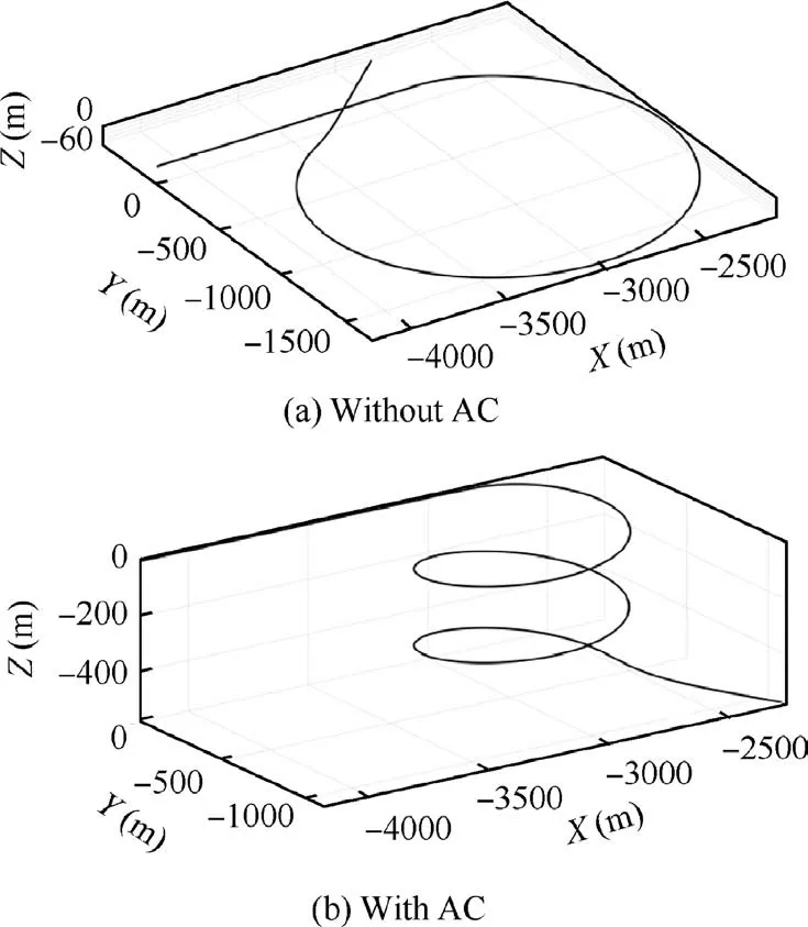
Fig. 8 Trajectory of steady turning with τ=300 ms.
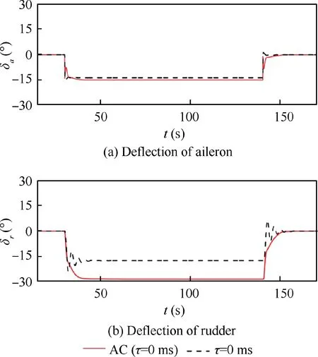
Fig. 9 Deflections of control surfaces in simulation with AC(τ=300 ms).
As ˙β model is a more exact model for the prediction of lateral-directional unsteady aerodynamic moments at high angles of attack, it is used to produce the aerodynamic loads in the simulations to evaluate the performance of AC. As shown in Tables 1 and 2, the difference between ˙β model and the reference model is quite great, not only the values of state matrix elements, but also the stability according to coupling ratio. The simulation results of τ=100 ms and 300 ms are both shown in Fig.10,and compared with the simulation results of no delay case.The trajectories are illustrated in Fig. 11.
As can be seen, the flight modes are quite different according to different time delays. In the 100 ms delay case, the rudder and aileron are deflected to limitation in the entry and recovery phases of the hover.The rate of descent of the turning is much larger than the no delay case.In the 300 ms delay case,the aircraft has come into a typical steep spiral mode rather than the steady turning. According to the stable and unstable regions of coupling ratio,the deflections of aileron and rudder are significantly different. The rudder is saturated for most of the time in the maneuver. With the increase of time delay,more additional control deflections are required due to the large difference between the controlled plant(˙β model)and reference model. The effectiveness of the adaptive controller is not satisfactory. Moreover, the control laws in the AC are non-universal with different time delays, as the state predictor is closely related to the value of delay.
Obviously, the wastage of control surface deflection for model tracking in the conventional aerodynamic derivative based adaptive controller is unacceptable at high angles of attack. Thus another method with less deflection wastage is needed.
4.2. Gain-prediction compensator
4.2.1. Description of gain-prediction approach
As discussed above, the degradation of flying qualities is mainly caused by the mismatch of stability augmentation gains rather than the errors of state parameters in time delay conditions. If the feedback gains can be corrected to the right one,the issue will easily be solved.In the lateral-directional motions at high angles of attack, the feedback gains are switched according to the regions of coupling ratio.Thus the prediction of feedback gains is equivalent to the prediction of coupling ratio.Then a gain-prediction approach is proposed to improve the SAS based on ˙β model. Fig. 12 shows the block diagrams of the original SAS and the improved SAS based on gainprediction.
As illustrated, the step of coupling ratio determination is out of the main loop in the improved SAS. The commands of SAS are computed in parallel by both of the feedback gains,and selected before output to the actuators. Thus the delay in the commands selection step is mainly contributed by the sensor delay,which is much less than 20 ms.In the current adaptive control methods, this delay also exists in the step of measuring the state tracking error, and is usually ignored. In view of the engineering applicability, all the conditions are considered as the worst in this paper.This part of delay is then set as 20 ms. Thus the coupling ratio ηshould be predicted.Within such a small delay,the Lagrange’s interpolation is a quick and effective method.For the signals of y,yand ywhich are respectively with respect to the time of t, tand t,the signal y at time t can be calculated as

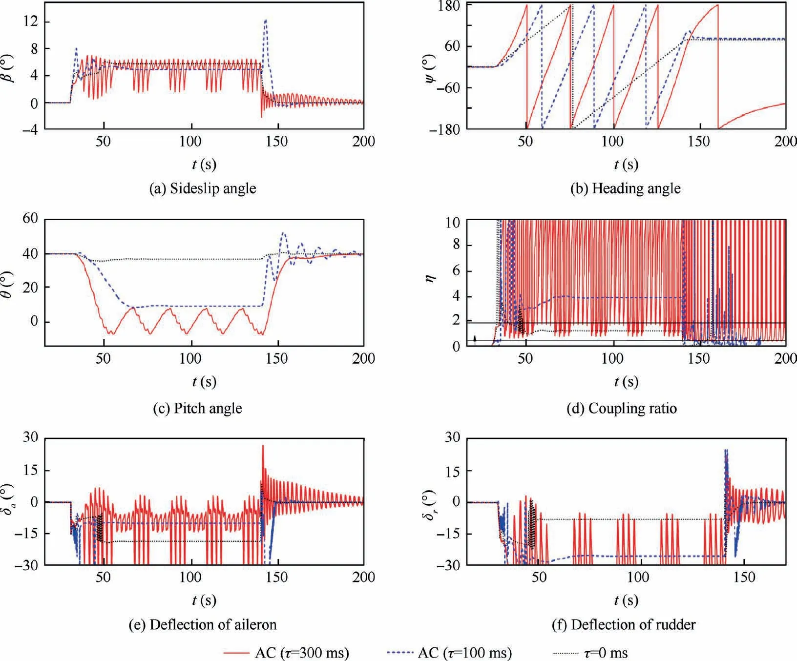
Fig. 10 Adaptive controller in simulation of ˙β model with AC.
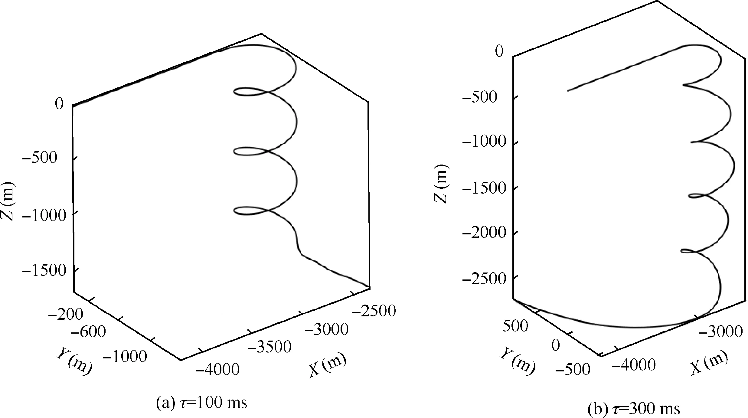
Fig. 11 Trajectories in simulations of ˙β model with AC.
In a rapid maneuver, the coupling ratio may vary sharply.By contrast,the variation of roll and yaw rates are more gradual.Thus the predicted coupling ratio is calculated by the predicted roll and yaw rates rather than direct interpolation, so that the prediction accuracy can be improved. Fig. 13 shows part of the prediction results in the simulation of ˙β model with τ=300 ms and without delay compensation (as shown in Fig. 2). The predicted coupling ratio is well consistent with that of real-time, except some of the inflection points. Fortunately,the feedback gains are determined by the region of coupling ratio rather than the exact value.Thus this slight error is insignificant. In fact, the prediction results are still acceptable even the scale of sensor delay is enlarged to 60 ms.Then commands of SAS are changed as
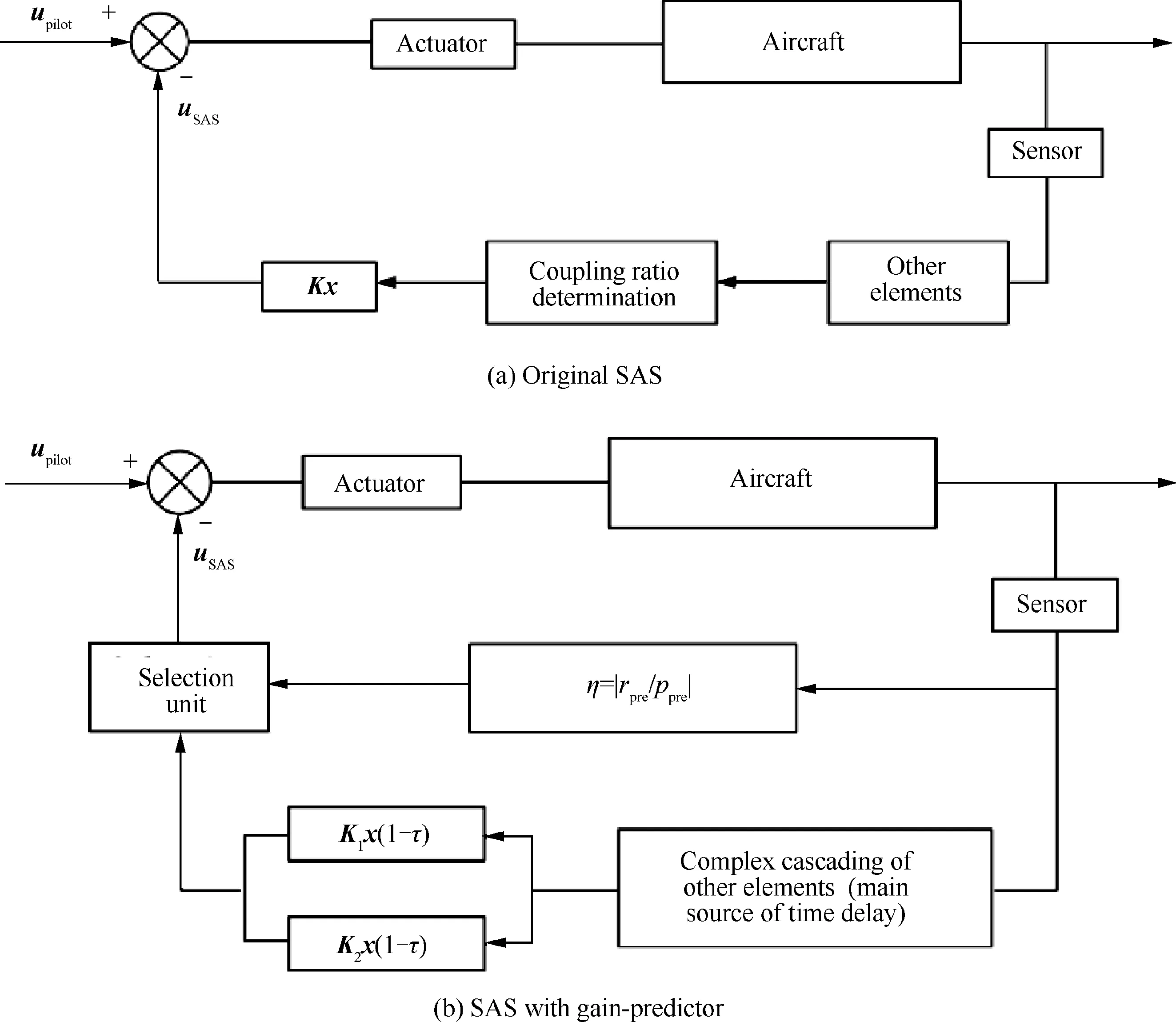
Fig. 12 Comparison between block diagrams with and without gain-prediction approach.
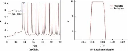
Fig. 13 Prediction of coupling ratio.

rather than the form of Eq.(10).As mentioned previously,this form of SAS is insensitive to the time delay.
As illustrated in Fig.12,the actuator is out of the feedback loop.As the effects of the actuator on the performance of control system are mainly caused by the deflection rate of control surfaces, the response rate is usually equivalent to a constant value of time delay τand incorporated into the total delay in the previous studies.That is, it is assumed that the control surface can always be deflected to the required position after τseconds. However, the required deflection of control surface cannot always be achieved due to the continuously changed control commands in the complicated maneuvers.Thus in this paper, the deflection rates of rudder and aileron have not been equivalent to a time delay. According to the design standardyof military aircraft,the control surface should achieve the maximum deflection within 0.2 s (All the factors are included such as the time of manipulating the control stick,deflection rate limitation, dead band of manipulation, etc).Thus the deflection rates of rudder and aileron of the investigated aircraft should be larger than 150(°)/s.In this investigation, the deflection rates are set as 150 (°)/s.
4.2.2. Compensation effectiveness of GPC
(1) Steady turning at α=40°
The GPC is first used for the time delay compensation in the steady turning.In all the following simulations,the aerodynamic loads are produced by ˙β model. Fig. 14 shows the simulation results of compensation of τ=100 ms.The oscillation of sideslip angle is completely eliminated by the GPC, and is well consistent with that of the no delay case. With the comparison of the trajectories and heading angles between the GPC case and no delay case, it is obvious that the effects of time delay are completely compensated. With the consideration of the limit of deflection rate, both the deflections of rudder and aileron are more gentle at about t=50 s.Furthermore, the deflections of control surfaces are almost the same as those in the no delay case, especially in the hover stage.Compared with the AC case,few additional deflection is needed in the GPC case to compensate the effects of time delay.
In the adaptive control method, the control laws should be adjusted in the design process according to the total time delay.How to determine the time delay margin of an adaptive controller is still an important issue for the control system engineers.In the GPC approach,the errors of state parameters caused by the time delay need not to be compensated, and the prediction of coupling ratio is independent of total time delay.Thus the controller is the same for the compensation of different time delays. Fig. 15 shows the performance of GPC in the steady turning with 300 ms delay. After the compensation of GPC, only minor difference exists between the cases of τ=0 ms and 300 ms. The trajectory of GPC case is the same as that in the maneuver without time delay.The distribution of eigenvalues (from 20 s to 160 s) is illustrated in Fig. 16.According to the distribution density, almost all the eigenvalues are located around the required ones. The effects of time delay on the flying qualities in the steady turning at high angles of attack are excellently compensated by the gain-prediction method.
(2) Herbst maneuver at α=50°
Now, the GPC is further expanded to other maneuvers which are more complicated and at higher angle of attack.
The Herbst maneuver is one of the most complicated poststall maneuvers for a high agility fighter.In the maneuver,the aircraft is first pulled up until the angle of attack reaches at the range from 50° to 70°. Then, the nose pointing is made a Uturn in seconds. The effectiveness of the GPC is examined in such a complicated maneuver with a large time delay of 300 ms. In order to simplify the process of simulation, the maneuver is started with a straight and level flight at α=50, and the rapid turn is conducted directly at t=90 s.As the efficiency of rudder is greatly reduced at such a high angle of attack, the efficiencies of rudder and aileron are both magnified to 4 times to simulate the effects of Thrust Vector Control (TVC). The magnified control power will not have any interference on the studies of time delay effects.
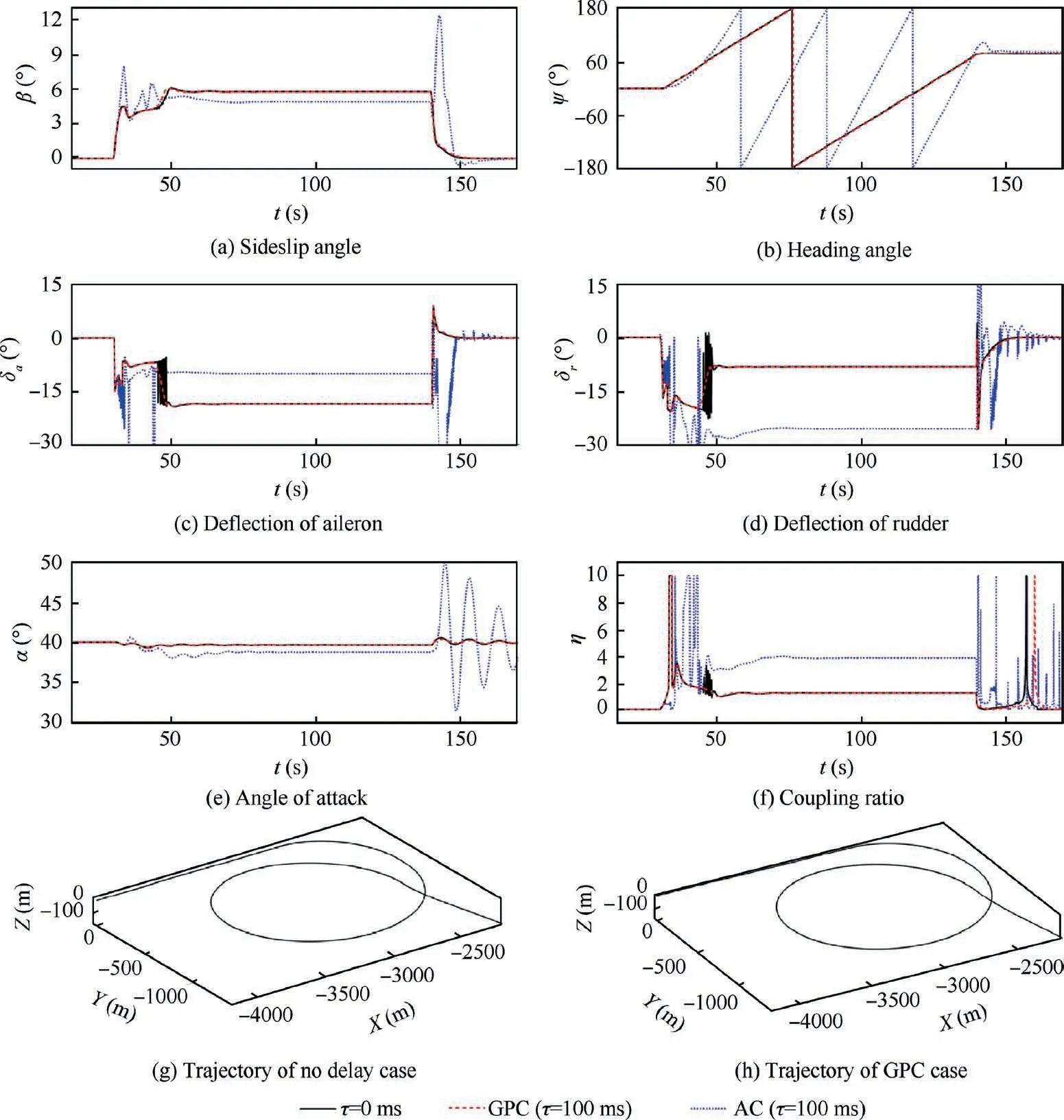
Fig. 14 Gain-prediction compensator in steady turning with τ=100 ms.
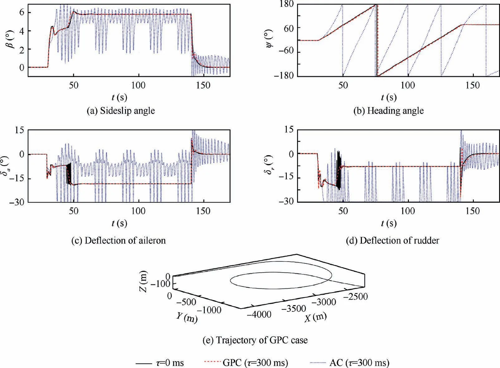
Fig. 15 Gain-prediction compensator in steady turning with τ=300 ms.
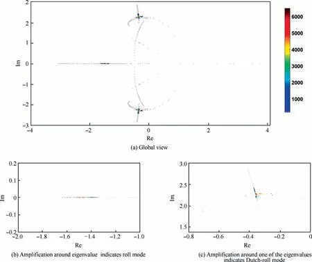
Fig. 16 Eigenvalues distribution in the compensation of 300 ms delay.
Fig. 17 shows the main parameters in the maneuver with τ=0 ms and 300 ms without compensation. Affected by time delay, the flying qualities are deteriorated sharply. With the same commands of pilot, the U-turn has not been completed in the maneuver with 300 ms delay.
Then both the AC and GPC are used for the time delay compensation in the Herbst maneuver. The simulation results are illustrated in Fig. 18. The performance of GPC is perfect,as the flight state is corrected to be the same as that without delay. Most importantly, few additional deflections of control surfaces are required by the GPC.
By contrast, the aircraft cannot keep the straight and level flight with the action of AC at such a high-α regime due to the saturation of rudder. It is because both the design of control laws and the reference model in current adaptive control approaches are based on the conventional aerodynamic derivatives, which cannot accurately reveal the unsteady aerodynamic characteristics at high angles of attack. Although the adaptive control approach has a great potential to deal with the uncertainty of aerodynamic model,it may be invalid when the uncertainty of reference model is large enough.
(3) Spin recovery at α=60°
In this section,the effects of time delay on the performance of SAS in auto-recovery from spin are investigated. Conceivably, the performance of AC is unsatisfactory and the simulation results are no longer given.
Fig. 19 shows the simulation results of GPC with a time delay of 300 ms, together with the results of τ=0 ms and 300 ms without compensation. The simulations are started with the straight and level flight in open-loop condition at α=60°. With a small disturbance, the aircraft enters into a spin. At the stable stage of the spin (t=200 s), the SAS is incorporated. Similarly, the control efficiency should be magnified to 4 times.
In such a complicated flight state, the time delay has a strong impact on the performance of SAS. When the delay is up to 300 ms, the aircraft cannot be recovered from the spin without delay compensation.The simulation is divergent after the incorporation of SAS.
When the gain-prediction method is used, the effects of time delay can be well compensated. When the SAS works together with the GPC, the oscillation of rudder is more violent than that of no delay case in a short time. At the same time, the sideslip angle is mildly oscillated but convergent rapidly.The adverse effects of time delay on the control system can be availably compensated.
4.3. GPC combined with MRAC
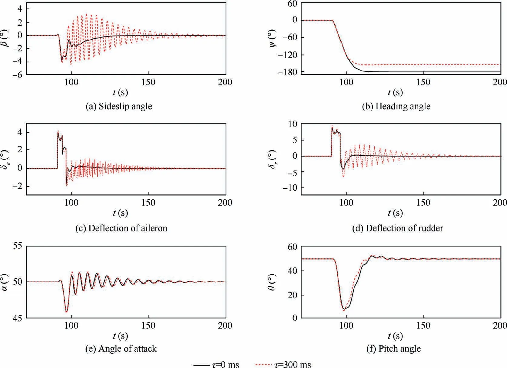
Fig. 17 Simulations of Herbst maneuver with τ=0 ms and 300 ms (without compensation).
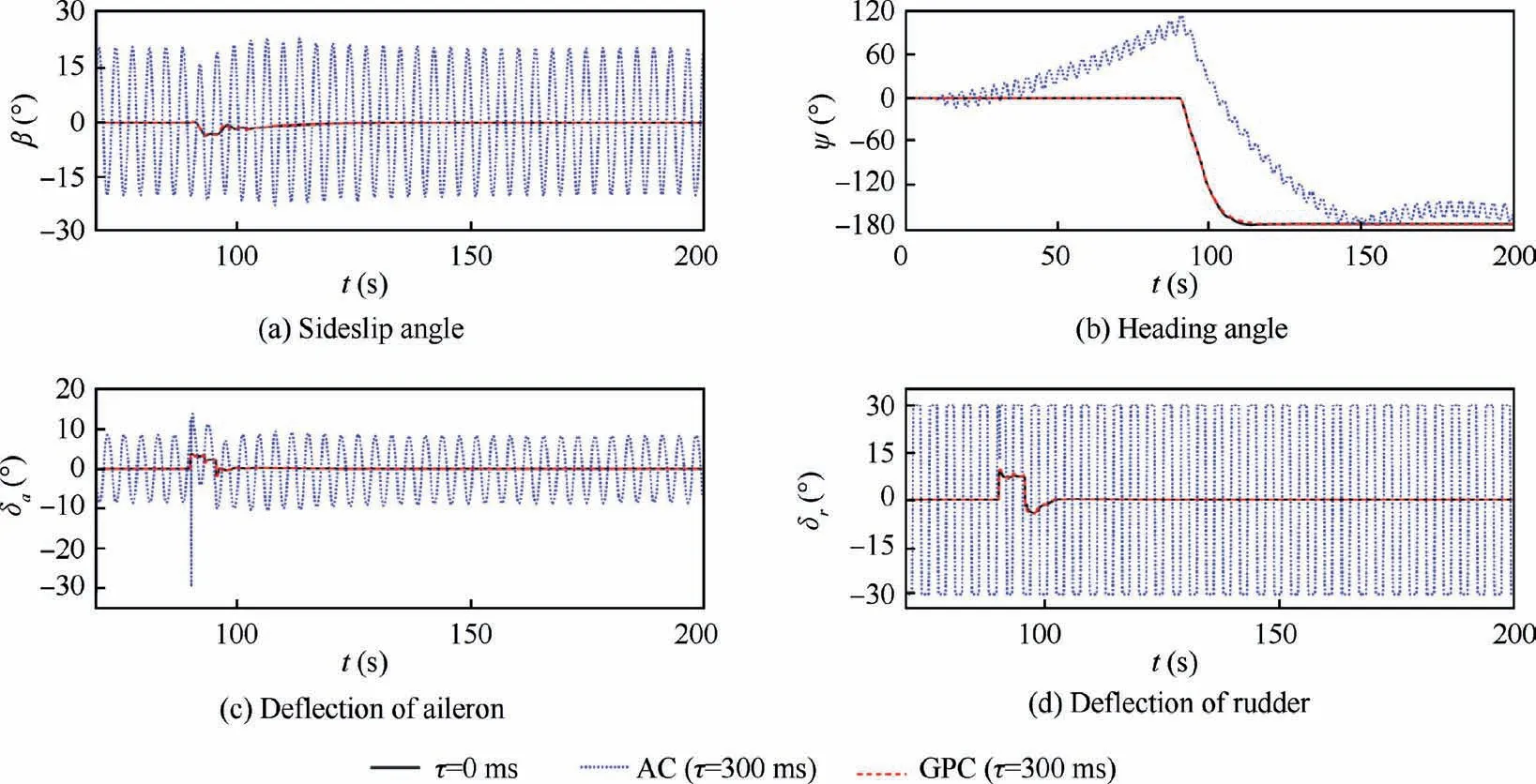
Fig. 18 Compensation of time delay in Herbst maneuver.
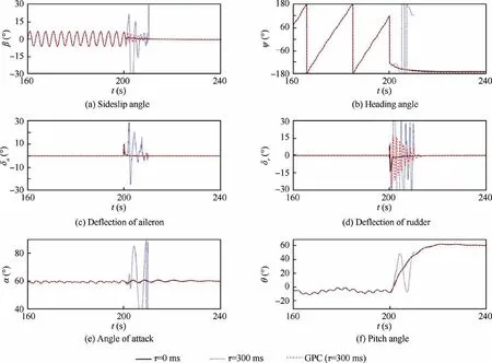
Fig. 19 Compensation of time delay in spin.
As discussed above, the effects of time delay on the flying qualities in different maneuvers at high angles of attack can be compensated by the gain-prediction approach, even when the delay is up to 300 ms. Thus it has been fully adequate for the requirements in engineering practice, as the maximum allowable time delay of Level 3 flying quality is 250 ms. Nevertheless, a much more extreme condition is investigated in this section. In the GPC method, only the mismatch of feedback gains is corrected. The errors of state parameters are neglected, because it will not introduce significant effects on the flying qualities within a limited time delay. However, when the value of time delay is large enough, the state errors are non-negligible, since the control commands of stability augmentation are calculated by these state parameters. As the adaptive control approach is inherently advantageous for addressing uncertainty, a MRAC is combined with the GPC to compensate the errors of state parameters caused by very large time delay.
Different from the conventional adaptive controller, the state predictor is replaced by the gain-predictor. In addition,the reference model is rewritten as

where A(t) and K(t) are the open-loop state matrix and the feedback gains, both of which are calculated by the linearized ˙β model and switched according to stable and unstable regions of coupling ratio.
The adaptive laws of MRAC input are

Thus the adaptive laws are associated with the stable and unstable regions of coupling ratio, and can be used the same as stability augmentation gains in the GPC.
Fig. 20 shows the compensation results of both the GPC and GPC+MRAC method in the steady turning at α=40°of 500 ms delay.
In the GPC case, the mismatch of stability augmentation gains is effectively addressed.In the turning stage,the coupling ratio is maintained in the unstable region for a long time.Thus the feedback gains need not to be switched. However, due to the state errors caused by such a large delay, the oscillation of sideslip angle is obvious and similar to that of the no compensation case with 100 ms delay (shown in Fig. 2), but the amplitudes of control deflections are much smaller. It is also demonstrated that the flying qualities are much more sensitive to the gains mismatch than the state errors.
When the GPC+MRAC method is used, the oscillations in the circling stage are eliminated. Both the adverse effects of gains mismatch and state error can be compensated. It is obvious that the performance of the adaptive control approach can be greatly improved by the increased accuracy of reference model.
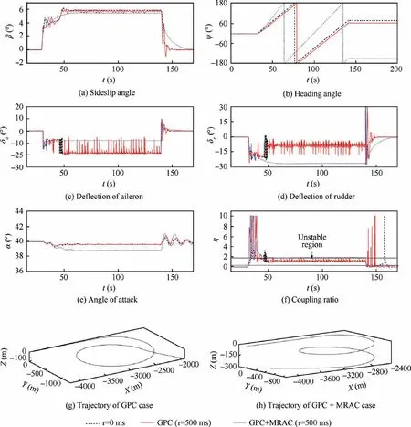
Fig. 20 Compensation of very large time delay.
However, with the same pilot commands, the trajectory of the steady turning in the GPC+MRAC case is different from those in the no delay case and GPC case. This difference is caused by the inconformity between the linearized and nonlinear forms of ˙β model. Meanwhile, additional deflections of control surfaces are required for tracking the reference model.These extra loss of control power caused by the model tracking should be carefully weighed,due to the sharply decreased control efficiency in high-α conditions. Theoretically, the additional deflection can be reduced by a more exact reference model (e.g. more sophisticated segmentation of coupling ratio in the linearized ˙β model). However, the reference model can only be expressed as a linearized form. Thus the uncertainty always exits at high-α regime. Furthermore, the frequent change of adaptive laws due to the variation of reference model will decrease the bounds of acceptable uncertainty,which has been fully discussed in the previous investigation on the stability margin of adaptive controller. As the GPC method has been capable of addressing the time delay which is larger than the maximum allowable value in the current design standard of military aircraft, the GPC+MRAC approach is suggested only as an alternative scheme to deal with the extreme situation at high angles of attack.
5. Conclusions
Based on ˙β model,the effects of time delay in the SAS at high angles of attack are investigated in this paper. The major inducement of flying qualities degraded by time delay in control systems are analyzed. Then an adaptive controller based on the conventional aerodynamic derivative method and a gain-prediction compensator based on ˙β model are respectively designed for the compensation of time delay effects in the lateral-directional maneuvers at high angles of attack.Finally,a gain-prediction compensator combined with model reference adaptive controller is designed based on the ˙β model,and used to address the very large time delay in high-α maneuver. The performance of different compensators is compared. The conclusions are drawn as follows:
(1) In the flight control system with time delays, the effects of feedback gains mismatch on the flying qualities are much greater than that of the state errors. Within the allowable maximum delay of design standard,the errors of state parameters, which is commonly considered as the major factor of time delay affecting the flight control systems in previous studies, will not lead to obvious degradation of flying qualities.
(2) The performance of adaptive control method for time delay compensation deeply depends on the precision of the reference model. As the model uncertainty of the conventional aerodynamic derivative method is large at high angles of attack,additional deflections of control surfaces are required for urging the real flight state to track the output of the reference model.This loss of control power has never been considered in the previous investigations and is unacceptable at high-α regime due to the sharp decline in control efficiency. In addition,the flight trajectory under the action of adaptive controller is quite different from the original state without delay. Whether the flying qualities are ‘‘compensated”or‘‘changed”,it is difficult to distinguish due to the lack of tools to analyze the performance of adaptive controller.
(3) According to ˙β model, a gain-prediction method is proposed to address the time delay in lateral-directional SAS at high angles of attack. Compared with the conventional adaptive control approach, the gainprediction compensator is much simpler and more efficient. The simulation results of different maneuvers at high angles of attack show that within 300 ms delay,which is larger than the maximum allowable value in current design standard,the flight state can be corrected to the same as that of no delay case. Furthermore, few additional control power is required in the gainprediction method. With a larger time delay, a gainpredictor combined with model reference adaptive controller method is further presented, by using the linearized ˙β model as a reference model. The performance of this compensator is significantly better than the conventional adaptive controller in addressing very large time delay, attributed to the more accurate reference model.
In the longitudinal flight control system,the feedback gains vary with different regions of angles of attack,which is similar to the lateral-directional gains with respect to coupling ratio.Thus the compensation approach of time delay proposed in this investigation can be further expanded to the longitudinal control system.
Declaration of Competing Interest
The authors declare that they have no known competing financial interests or personal relationships that could have appeared to influence the work reported in this paper.
Acknowledgement
This work was supported by the National Natural Science Foundation of China (No. 11872209).
 CHINESE JOURNAL OF AERONAUTICS2021年4期
- CHINESE JOURNAL OF AERONAUTICS的其它文章
- Dual stability enhancement mechanisms of axial-slot casing treatment in a high-speed mixed-flow compressor with various tip clearances
- Development cost prediction of general aviation aircraft using combined estimation technique
- Improvement on shaped-hole film cooling effectiveness by integrating upstream sand-dune-shaped ramps
- Modeling and parameter identification of linear time-varying systems based on adaptive chirplet transform under random excitation
- An experimental method to obtain the hard alpha anomaly distribution for titanium alloy aeroengine disks
- Vibration analysis and control technologies of hydraulic pipeline system in aircraft: A review
