Vibration analysis and control technologies of hydraulic pipeline system in aircraft: A review
Peixin GAO, To YU, Yunlin ZHANG, Jio WANG, Jingyu ZHAI
a School of Electromechanical and Automotive Engineering, Yantai University, Yantai 264005, China
b School of Mechanical Engineering, Dalian University of Technology, Dalian 116024, China
KEYWORDS Aircraft;Hydraulic pipeline;Vibration analysis;Vibration control;Vibration failure
Abstract Vibrations in aircraft hydraulic pipeline system, due to multi-source excitation of high fluid pressure fluctuation and serious vibration environment of airframe,can cause the pipeline system vibration failures through overload in engineering field.Controlling the vibrations in hydraulic pipeline is a challenging work to ensure the flight safety of aircraft.The common vibration control technologies have been demonstrated to be effective in typical structures such as aerospace structures, shipbuilding structures, marine offshore structures, motor structures, etc. However, there are few research literatures on vibration control strategies of aircraft hydraulic pipeline.Combining with the development trend of aircraft hydraulic pipeline system and the requirement of vibration control technologies, this paper provides a detailed review on the current vibration control technologies in hydraulic pipeline system. A review of the general approaches following the passive and active control technologies are presented,which are including optimal layout technique of pipeline and clamps,constrained layer damping technique,vibration absorber technique,hydraulic hose technique,optimal pump structure technique,and active vibration control technique of pipeline system. Finally, some suggestions for the application of vibration control technologies in engineering field are given.
1. Introduction
Aircraft hydraulic pipeline system is a typical high-pressure and high-speed system, including pipeline bodies, pipeline fittings,supporting parts(brackets and clamps).etc.The hydraulic pipeline system is an important mechanical and electrical system for aircraft control tasks, such as landing gear, flaps and deceleration plate, aileron, elevator and rudder assistant control, wheel brake and front wheel turning, etc.Fig. 1 shows the distribution of the hydraulic pipeline system in the aircraft. Pipeline system usually starts from the transmission device of aircraft accessory casing of aeroengine, then it lays down to the landing gear wheel cabin and the rear accessory cabin. Moreover, a large number of pipelines intersect each other due to the space constraint,and the gaps between pipelines and adjacent accessories are generally very small.
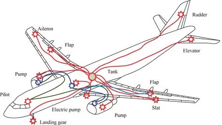
Fig. 1 Distribution of aircraft hydraulic pipeline system.
Compared with the common hydraulic pipeline system,the aircraft hydraulic pipeline system has its special characteristics.(A) The distribution of the pipeline system is wide and large, and the length of pipeline can reach more than several hundred meters. (B) The layout of the pipeline system is complex,and the space is very narrow by the aircraft structure.(C)The high-pressure variable axial piston pump is commonly used in present aircraft hydraulic system. The fluid pressure value of pump has reached to 350 bar, and the pulsating flow output causes strong fluid pressure fluctuation in the pipeline,which will induce serious pipeline vibration.(D)The vibration of the aircraft body and aeroengine is serious,and the hydraulic pipeline system suffers from serious vibration by working environment.
In engineering field, various types of faults often occur in aircraft hydraulic pipeline system, they are mainly manifested as vibration failure of pipeline system, affecting flight safety and causing serious losses. According to the US statistics,the faults of fuel, air and hydraulic pipeline system account for 50% to 60% of the total faults of aircraft components.Statistics of Russian aircraft show that the faults of fuel,lubricating oil and hydraulic system also account for more than 50% of the total faults of aircraft. There are many cases of vibration failures for aircraft hydraulic pipeline system in recent years.In the field of aeronautical electromechanical system, the vibration faults of hydraulic pipeline system have been plaguing aircraft designers, which have serious impact on flight safety.
Vibration failure modes of hydraulic pipeline system mainly include excessive vibration and vibration fatigue.The reason of excessive vibration is the pipeline resonance.When the fluid pulsation frequencies or the base excitation frequencies are close to the pipeline natural frequencies, the pipeline structural resonance would be induced,which will directly lead to the relative large displacement of the joint surface between the pipeline connection and the fixed part.Finally,it causes the surface friction or damage, as well as the collision with the adjacent pipeline.The excessive vibration of the pipeline will also lead to the loosening of pipe fittings. Vibration fatigue of pipeline generally refers to the long time working of pipe body, pipe fittings,bracket,clamp and other components under strong fluid pulsation and strong base aeroengine excitation.Especially when the pipeline structural resonance occurs, cumulative damage is formed due to high vibration stress,and then the cracks propagation and fracture are caused by a certain number of cycles.The common vibration failure modes of aircraft hydraulic pipeline system in engineering field are listed as follows:pipe collision and wear, pipe crack, pipe fitting wear, pipe fitting loosening, support loosening, bracket crack, clamp loosening,clamp fracture, etc. The typical vibration failure photos of hydraulic pipeline system in aircraft are shown in Fig.2.
The hydraulic pipeline system is one of the most important mechanical and electrical systems to ensure the flight safety of aircraft, and the vibration problems are very prominent in engineering field.Due to the wide spatial distribution and complex spatial layout, the complex vibration behavior and vibration failure mechanism of the hydraulic pipeline system under the multi-source excitation of pump and aeroengine are still challenging for aircraft designers at present. Therefore, it has been motivated to investigate the vibration characteristics and control technologies of hydraulic pipeline system in aircraft.
This paper provides a comprehensive review of the literature for vibration analysis and control technologies of hydraulic pipeline system in aircraft. Firstly, the vibration characteristics of aircraft hydraulic pipeline are presented.Then a review of general vibration control technique following the passive and active control technologies are presented,such as the high damping support clamp, optimum layout design of clamps, constraint layer damping for pipeline system, vibration absorber for pipeline system, hydraulic hose technique, optimal pump structure technique, and active vibration control technique. Finally, some suggestions of the vibration control technologies for engineering applications are discussed by advantages, disadvantages and remaining research challenges.
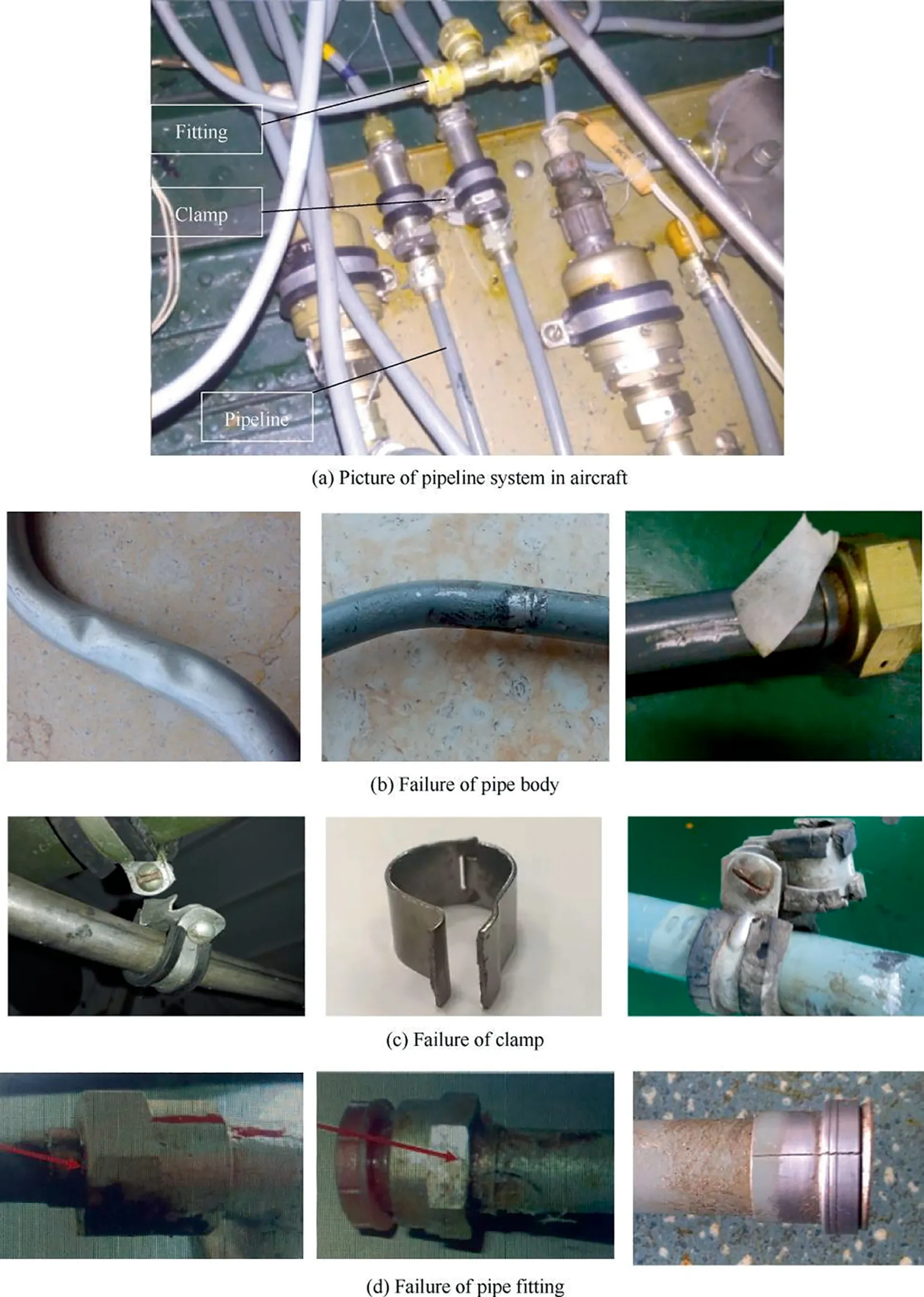
Fig. 2 Pictures of typical faults of hydraulic pipeline system in aircraft.
2. Vibration of hydraulic pipeline in aircraft
The hydraulic pipelines are directly connected to each other through pipe fittings and clamps. The vibration mechanism is very complex, including the coupling vibration between pipeline and airframe, the coupling vibration between pipeline and casing, and the coupling vibration between parallelpipelines and fluid structure interaction. This section presents a detailed review of vibration characteristics and failure mechanism of hydraulic pipeline system in aircraft.
2.1. Vibration characteristics of pipeline system
The vibration mechanism of hydraulic pipeline refers to the coupling vibration of pipeline under the fluid transient. The phenomenon of pipeline related to unsteady fluid motion is termed as Fluid-Structure Interaction(FSI),and the interaction is manifested in pipeline vibration and perturbations in fluid pressure. The sudden opening or closing of valve and the mechanical excitation can induce the coupling vibration of pipeline and moving fluid. Notable contributions were conducted by researchers.Three mechanisms are distinguished which include Poisson coupling, friction coupling and junction coupling.Poisson coupling is related to the stress perturbation caused by fluid pressure transient that translates to axial stress perturbation by the Poisson ratio coefficient.The stress wave in the pipe wall can travel faster than water hammer wave, it is commonly three to five times greater than water hammer wave in the pipeline.Friction coupling refers to the mutual friction between fluid and pipeline. Junction coupling is associated with the changes in fluid momentum at discrete location in pipeline such as valves, bends and tees, etc.
To describe the dynamic behavior of pipeline considering FSI effect,several FSI models are proposed according to their basic equations. The early two-equation was proposed which referred to classical water hammer theory,where the fluid pressure and velocity were the only two unknown parameters.By adding two structural equations, the four-equation model was obtained.Tijsselingproposed an exact solution for FSI four-equation model in terms of a simple recursion. Xu and Jiaoproposed an improved exact solution of axial liquidpipe vibration with time-line interpolation for FSI fourequation model. Adding the radial inertia forces, the sixequation model can be obtained. Considering the axial and in-plane vibration for planar pipe systems, the eight-equation model was obtained.Adding two torsional equations and four lateral equations into the eight-equations, the most detailed fourteen-equation model was obtained to describe the axial motion, lateral motion, and torsional motion of threedimensional pipeline systems.The four-equation model and eight-equation model can predict the vibration characteristics of simply pipelines accurately, and fourteen-equation model can analyze the vibration of complex configured pipelines efficiently.
The vibration behavior of hydraulic pipeline system in aircraft is complex in the following aspects. Firstly, the structure of pipeline system is complex, which usually consists of more than two pipelines connected by fitting to form a complex pipeline network system, as shown in Fig. 3.Secondly, the working environment of pipeline system is complex, including the fluid pressure fluctuation by hydraulic pump,the base excitation generated by aeroengine, the random excitation generated by aircraft body, the airflow excitation and noise excitation, etc. The related researches are reviewed as follows.
There are some reported literatures about the vibration characteristics of hydraulic pipeline system under pump fluid excitation in aircraft. For example, Wang et al.presented a new approach to predict the inlet pressure of aircraft hydraulic pump based on pressure wave propagation method.The vibration of pipeline under pressure fluctuation excitation could cause vibration fatigue cracks of pipeline system.The vibration response of aero hydraulic pipeline under pump fluid fluctuation was investigated based on experimental and numerical method. The pressure fluctuation of the hydraulic pipeline was measured by the pressure pulsation sensor. The experimental results showed that the pump fluid pressure fluctuation curve contained a number of sinusoidal components,as shown in Fig. 4.The vibration response of the spectral map for the hydraulic pipeline was shown in Fig. 5.When the pressure fluctuation harmonics were close to the natural frequencies of the pipeline, the mechanical resonance would occur which can cause serious vibration.
Ouyang et al.carried out the vibration analysis of complex hydraulic pipeline in aircraft. The numerical results showed that the pipeline length between the two supports was the most important factor for the changing natural frequency of pipeline, and the increasing radius can obviously increase the resonant frequency, as shown in Fig. 6.Moreover, a three-dimensional finite element model of aircraft hydraulic pipeline was presented, and the experimental and simulation results can match closely in stress analysis.Jiaocarried out the vibration simulation for aircraft hydraulic pipeline system.The characteristic impedance solution method was presented and the harmonic frequencies of the system were evaluated. The mechanism of pump fluid fluctuation and fluid coupling vibration of aircraft hydraulic pipeline system were given from the engineering point of view.
There are some reported literatures about the vibration characteristics of hydraulic pipeline system under base excitation in aircraft. Kang et al.investigated the load spectrum of aeroengine pipeline based on vibration response solving method. The results showed that the primary external load for the pipeline installed on the fan casing and high pressure compressor casing were the harmonic excitation, as shown in Fig. 7.While the primary external load for the pipeline installed on the combustion casing and outlet were the random excitation, as shown in Fig. 8.
Liu et al.carried out dynamic reliability of aircraft hydraulic pipeline under random vibration,a new quantitative evaluation method is proposed for the safety assessment and design of pipeline under random external vibration.The stress analysis of aircraft hydraulic pipeline under acceleration load excitation and random vibration were investigated based on the response spectral analysis method through the comparison of the theoretical calculation, simulation and experiment.The results can provide the theoretical guidance for the vibration analysis of hydraulic pipeline in aircraft.
The modeling methods of hydraulic pipeline in aircraft have been published in the open literatures. Gao et al.presented a developed model reduction approach for the vibration analysis of hydraulic pipeline with long distance and multi-supports in aircraft, as shown in Fig. 9.Some parts of hydraulic pipeline system can be simplified by the specific structural forms, and the obtained results indicated that the current approach could reduce the computational cost significantly with sufficient accuracy. Ouyang et al.developed a mathematical model and solved in the frequency domain with Transfer Matrix Method(TMM)to predict the vibration of the aircraft hydraulic pipeline. Li et al.analyzed two typical pipelines (straight pipe and curved pipe) in aircraft based on Finite Element Method (FEM). The simulation and experiment results showed that adjusting the clamp length was an effective way to change the natural frequencies of pipeline in aircraft.Wang et al.presented a solution procedure combining the Method of Characteristics (MOC) and the Finite Element Method(FEM) to solve the coupled vibration model for aircraft hydraulic pipeline system.
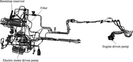
Fig. 3 Picture of aircraft hydraulic pipeline.25
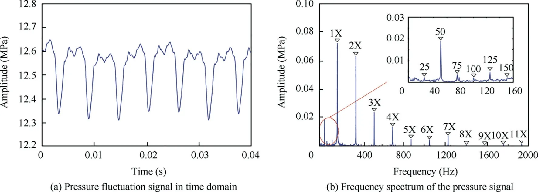
Fig. 4 Pressure fluctuation signal by measurement.27
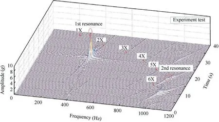
Fig. 5 The 3-dimensional spectral map of pipeline during pump sweep by measurement.27
The MOC is a powerful method that has been widely employed for FSI models in time domain, but for complex pipelines, it suffers the obvious interpolation error that decreases on fines grids. The TMM is an effective method to solve FSI problems in frequency time, but for long distance pipeline, it suffers the round-off error instability. The FEM is a powerful method for solving problems in structural dynamics, but for FSI problems, it suffers the low calculation efficiency.The aircraft hydraulic pipeline system has long span and complex characteristics. In practical engineering applications, the hybrid method may be a new direction for solving FSI problems in the future.For example,The MOC is suitable to solve the hydraulic transients in simple pipeline, and the CFD (Computational Fluid Dynamics) is suitable to capture complex local 3D features inside complex elbow pipeline,valves and pumps. However, the whole modeling of pipeline,valves and pumps by CFD are time consuming. Therefore,the hybrid MOC-CFD method can be presented as a new multi-scale modeling approach to analyze the FSI problems in aircraft hydraulic pipelines. The hybrid MOC-FEM can improve the computational efficiency compared to FEM method. In this method, the hydraulic equations are solved by MOC and the FEM is used to solve the structure equation.Moreover,a hybrid MOC-CFD-FEM method can also be proposed to analyze the FSI problems with high efficient and sufficient accuracy in the future.
Compared with the high pressure pulsations inside hydraulic pipeline, the low pressure pulsations inside the pipeline are more complex and dangerous due to the appearance of cavitation and gas bubbles inside the pipeline.For the hydraulic system, the supply and return hydraulic pipeline under low pressure can cause water hammer accompanied by the generation of cavitation and gas bubbles by the sudden closing of valve. The reason for this phenomenon is that the working pressure is close to atmospheric pressure.The bubbles and cavitation will affect the performance of hydraulic system seriously, and it has a great impact on the process of pressure pulsation.Therefore,compared with the high pressure hydraulic pipeline, the low pressure hydraulic pipeline with gas bubbles and cavitation is more complex and important for the design of hydraulic pipeline system.
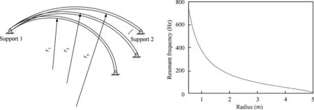
Fig. 6 Radius influence on curvature resonant frequency.25
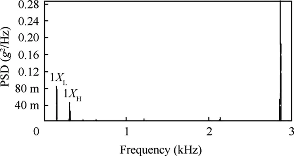
Fig. 7 External loads for pipelines installed on casing.33
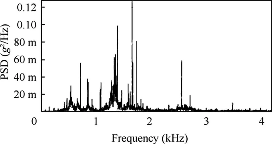
Fig. 8 External loads for pipelines installed on combustion casing.33
There are some reported literatures about the hydraulic pipeline under low pressure pulsations. Some notable contributions were conducted by researchers.Kojima et alinvestigated the fluid transient phenomena with cavitation in the pipeline with the sudden closure of valve. A gasnonbubbly flow model was proposed to predict pipeline pressure transients, and the numerical results were compared with the experimental results. A comprehensive review of the water hammer with column separation was investigated.Shuproposed a developed cavitation model to simulate pipeline pressure transients. The proposed model was verified by a comparison of experimental results on upstream, midstream and downstream cavitation. A new mathematical model for pressure and flow transients was presented and a novel method using genetic algorithms for parameter identification was proposed by Li and Jiang et al.to investigate the transient pressure in hydraulic pipelines.The calculation results showed close correspondence with experimental data.
For the vibration analysis software and algorithms of hydraulic pipeline under low pressure pulsations. Many methods are available in the open literature, such as method of characteristics (MOC), finite element method (FEM), and Finite Difference Method (FDM).etc. Wylie et al.used the MOC to simulate the generation of cavitation.In this method,the formation and collapse of cavitation was setting as an internal boundary condition, and the influence of gas bubbles was not included in the liquid column separation model.Shuproposed a developed FEM to analyze the pipeline pressure transients.In this method,basic equations were approximated as ordinary differential equations represented in state space form,and the accuracy of the FEM was verified by the method of characteristics. Jiang et al.used the FDM to analyze the pressure transients with cavitation. The cavitation growth and collapse mechanism were captured by upstream and downstream of hydraulic pipeline. The simulation results of the FDM showed higher accuracy than MOC. A hybrid method combing the FDM and Matlab Simulink platform was proposed to predict pressure transients accompanying cavitation and gas bubbles.The simulation results showed that the combining FDM with MATLAB Simulink can provide a new method for predicting pressure transients in hydraulic pipeline system.
2.2. Vibration failure mechanism of pipeline system
In the past decades,the vibration failures of aircraft hydraulic pipeline system have been very prominent, and various types of faults have been occurred in hydraulic pipeline system.They are mainly manifested as vibration failure of pipeline system,affecting flight safety and causing serious losses. The research progress of vibration failure mechanism of hydraulic pipeline system in aircraft is listed as follows.
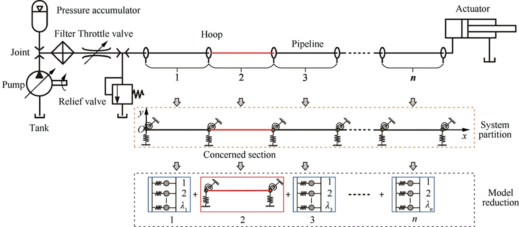
Fig. 9 Schematic diagram of hydraulic pipeline system for model reduction in aircraft.2
Structure vibration failure has been plaguing aircraft designers,which has serious impact on flight safety.The crack concept,quantitative fractography,fatigue testing are essential for analyzing the fatigue crack growth and prediction.During the flight of an aircraft,it was found that the hydraulic oil indication dropped, and the hydraulic oil leaked out of the pipeline. The test results showed that the hydraulic pipeline was vibration fatigue cracks. The main reason for the cracks of the hydraulic pipeline was that the aeroengine caused the pipeline structural resonance with large vibration response amplitude.Panda et al.investigated the aircraft with an incident during a routine flight operation, where pilot noticed a thin trail of smoke coming out from the tail end of the aircraft.Results showed that there was a fatigue crack in one of the weld joint of the afterburner fuel manifold which resulted in fuel leakage in the form of streaks as shown in Fig. 10.
The pressure drop of hydraulic pipeline system was found in an aircraft by Liu et al.The cracks in hydraulic pipeline system was located at the root of flat nozzle, and it was the 12 mm away from the pipe fitting, as shown in Fig. 11.The causes of the faults were found by the vibration simulation analysis of hydraulic pipeline system, and the preventive and improving methods were proposed to solve the faults of hydraulic pipeline in aircraft.
Mehmood et al.investigated the two failure cases of the same hydraulic pipeline in aircraft, as shown in Fig. 12.The midair fractured pipeline and cracked pipeline caused hydraulic pressure loss, and it impaired the movement of control surfaces in aircraft.The failure of pipeline was investigated by visual examination. Results showed that the fluid pressure fluctuation and the stress concentration of circumferential groove were the main factors causing fatigue failure of hydraulic pipeline in aircraft. Lu et al.summarized the vibration failure of the hydraulic pipeline for an aircraft. The reason for the failure was that the natural frequency of the pipeline was close to the pulsation frequency of the hydraulic pump,resulting in structural resonance and high vibration stress of pipeline.The hydraulic pipeline suffered from serious vibration of fluid pressure fluctuation by the pump and base environment excitation by aeroengine, which could cause excessive vibration stress of the hydraulic pipeline, resulting the vibration failure of pipeline quickly in engineering field.
Vibration failures of hydraulic pipeline system mainly include excessive vibration and vibration fatigue. The reason of excessive vibration is the structural resonance. When the fluid pulsation frequencies or the base excitation frequencies are close to the pipeline frequencies, the pipeline resonance would be induced.It will directly lead to the relative large displacement of the fitting surface between the pipeline connection and the fixed part, resulting in surface friction or damage, as well as the collision with the adjacent pipeline.Some literatures have been reported the vibration failure of hydraulic pipeline in civil aircraft. Adib et al.investigated the failure of T-duct pipeline for a commercial aircraft, as shown in Fig.13.The damaged T-duct pipeline was carefully inspected and the microstructure and internal duct surface observation and mechanical test were performed.It was found that the damaged part was transgranular fatigue cracking.Results showed that the crack had initiated at around the inside surface, then the increments of cracking occurred and finally the fracture occurred.Moreover,the hydraulic pipelines in B737 and MA600 aircraft had also been reported about the vibration failure cases, and the vibration faults of hydraulic pipeline in aircraft were very prominent in engineering field.In the design of hydraulic pipeline, it is necessary to avoid pipeline vibration failures, especially to avoid the structural resonance of pipeline. The nature frequencies of pipeline should be far away from the pump fluid pulsation frequencies and aeroengine rotating frequencies.
For hydraulic pipeline system of aircraft, more failures occur in pipeline clamps and supports corresponding to pipeline structure. Clamp is a kind of standard part widely used in aircraft, which is usually used for connecting, fixing and supporting various pipelines in aircraft. Due to the serious working conditions,such as the high temperature and the serious vibration environment,the clamps and supports can often occur failures in engineering field,which will directly affect the performance of the system and flight safety.
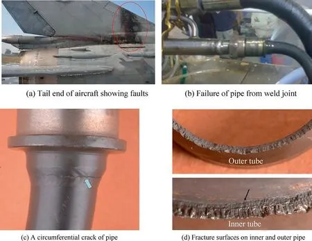
Fig. 10 A circumferential crack and fracture surfaces on inner and outer pipe.51

Fig. 11 Picture of crack location of hydraulic pipeline in aircraft.52
In engineering field, the failure modes of pipeline clamps and supports are clamp crack, clamp fracture, support crack and fracture. The main reason for clamp and support failures include the excessive vibration and vibration fatigue.When the fluid pulsation frequencies or the base excitation frequencies are close to the pipeline frequencies, the pipeline resonance would be induced,which will directly lead to the relative large stress between pipeline and support. The clamps and supports under strong fluid pulsation and aeroengine base excitation can form cumulative damage due to high vibration stress,and then the crack propagation and fracture are caused.Some literatures have been reported the vibration failure of pipeline clamps and supports in aircraft.For example, Liu et al.carried out the fracture fault analysis of pipeline clamps in aeroengine. The fracture position of the clamps with multiple fractures were all near the installation hole, and the macro morphology of the fracture was shown in Fig. 14.The fracture surface of the clamp had sufficient fatigue growth, no obvious instantaneous fracture area was found,and the fatigue band was thin,it was indicating that the fracture property was fatigue. The reason of clamps failure was that the fault position of clamp structure was caused by large initial local stress of tightening bolt. The serious vibration environment caused the increasing comprehensive stress, and the vibration fatigue fracture occurred. Zheng et al.summarized the failure analysis process of pipeline clamp in aircraft. It contained the micro inspection to determine the failure of the clamp, the judgment of the crack initiation position and propagation direction, and the judgment of the processing direction of the clamp and the streamline direction of the material.Results showed that the failure reason of the clamps was stress fatigue in aircraft.
Xiao et al.investigated the clamp with rubber layer failure in aeroengine. As shown in Fig. 15.The crack of the clamp rubber pad originated from the right angle of one or both ends of the clamp, then it extended longitudinally along the clamp.The fracture surface of the failed clamp was magnified and observed under the solid microscope. It was found that the crack originated from the inner side of the right angle at one end of the clamp gasket, the source area was rough, and no metallurgical defects were found. The failure of clamp rubber was caused by the combination of stress and temperature environment in which the heat-resistant performance of the material cannot meet the requirements. Li et al.carried out the damage effect of the heat and solar radiation environment on aero clamp rubber pad. Test results showed that many micro porous defects appeared on the surface of the rubber pad after aging in the damp heat and solar radiation environment, and the tensile properties of the clamp were greatly reduced.
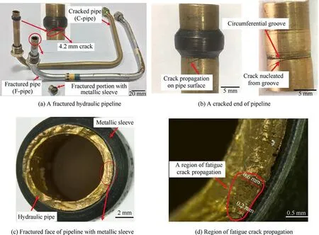
Fig. 12 Picture of fractured and cracked hydraulic pipeline in aircraft15
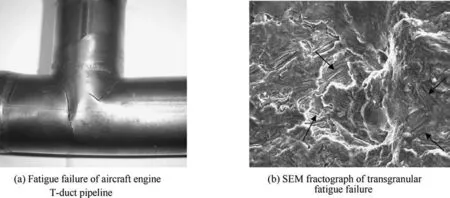
Fig. 13 Picture of fatigue crack location of aircraft T-ducts.57
During the test run process of the aeroengine, the pipe bracket support occurred fracture failure several times due to high cycle fatigue, as shown in Fig. 16.Numerical results showed that natural frequencies of pipeline were close to the engine rotating frequencies which directly leaded to the pipeline structural resonance. It caused the relative large stress of the support bracket and pipeline. The cumulative damage was formed due to high vibration stress, and then the crack propagation and fracture were caused by a certain number of cycles.Finally,the bracket support fracture failure can be solved by increasing the support stiffness to adjust the natural frequency of pipeline beyond the aircraft resonance frequency range.

Fig. 14 Picture of pipeline clamps crack in aeroengine.61
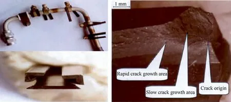
Fig. 15 Picture of clamp rubber pad fracture in aircraft.63
Li et al.investigated the clamp support fracture in the test run process of aeroengine. The fracture properties of the support were determined by the appearance inspection, fracture analysis,and surface micro inspection.The test results showed that the fracture properties of the clamp were high cycle fatigue fracture,as shown in Fig.17.The fracture fatigue source area showed clear and fine fatigue arc characteristics.The fatigue originated from the inner arc side surface of the middle area of the clamp bend, and a large number of clear and fine fatigue strips can be found in fatigue extension area of the fracture belt. The main reason for the fatigue fracture of the support was the stress concentration, and the vibration load accelerated the fatigue fracture of the support.
With the development of aircraft in recent years,the design concept of the whole pipeline system is constantly improved,which also puts forward higher reliability requirements for the pipeline clamps and supports. In order to reduce the failures of clamp,one way is to improve the stress corrosion resistance of the clamp support structure, such as selecting the appropriate type of clamp and reasonable structure to improve the clamp stress level,improving the clamp and support material, and improving the environmental adaptability of materials. Another way is to improve the manufacture level and assembly quality to reduce the assembly stress of clamps and supports. In the future, the pipe clamps and supports can be developed in the following directions,such as low weight,high temperature resistance, high vibration control performance,high pressure resistance,quick installation,good maintainability and high reliability.
3. Passive vibration control technologies
The aircraft hydraulic pipeline system has its special characteristics, such as the wide distribution of the pipeline system, the complex layout of the pipeline system,the strong fluid pressure fluctuation of pump, and the serious vibration of the aircraft body and aeroengine. The hydraulic pipeline system suffers from serious vibration by working environment. Therefore, it has been motivated to investigate the vibration control technologies of hydraulic pipeline system to ensure the flight safety of aircraft.
Vibration control technologies of aircraft hydraulic pipeline systemcanbecharacterizedaspassiveandactivemethod.Passive vibration control technologies do not require an external power andutilizethepipelinemotiontodevelopthecontrolforce.Therefore,thepassivevibrationcontroltechnologiesofaircrafthydraulic pipelinesystemcanbeimplementedasfollows:
(1) High damping support clamp.
(2) Optimum layout design of clamps.
(3) Constraint layer damping for pipeline system.
(4) Vibration absorber for pipeline system.
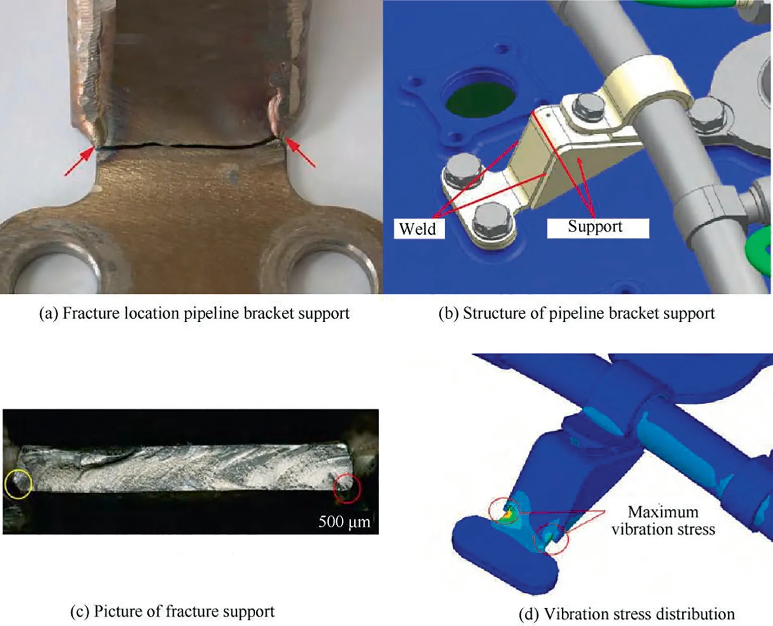
Fig. 16 Picture of pipe bracket support fracture in aircraft.67
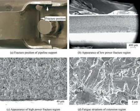
Fig. 17 Picture of pipeline support fracture in aeroengine.68
(5) Vibration absorber for hydraulic pipeline fluid.
(6) Other passive vibration control methods.
3.1. High damping support clamp
The support clamp of hydraulic pipeline in aircraft is an important part to enhance pipeline stiffness and tighten pipeline position.Clamp not only meets the conditions of cushioning and reducing vibration due to the particularity of working environment, but also it requires the high temperature resistance and wear resistance.
According to different structures,clamp can be divided into rigid clamp and elastic clamp.For the elastic clamp,the rubber material is used to increase the wear-resisting and reduce vibration of aircraft pipeline, as shown in Fig. 18. The clamp consists of the rubber pad, metal sheet and bolt. The function of bolt and metal sheet are pre-tightening and fixing the pipeline.The rigid clamp with metal rubber is usually applied in aeroengine pipeline, as shown in Fig. 19. The rigid clamp consists of the metal rubber, metal sheet and bolt. The metal rubber can not only reduce pipeline vibration, but also it meet the requirements of high temperature resistance and wear resistance. The structure characteristics of clamps are single and parallel to fix the single and parallel pipelines in aircraft, as shown in Fig. 20.
The high damping clamp is an effective method to reduce the vibration of pipeline in aircraft.The stiffness and damping coefficient of clamp have a great influence on the vibration characteristics of pipeline system. Many researchers are studied the effect of clamp parameters on pipelines. The research on the characteristics of high damping support clamps are reviewed as follows.
The damping clamp can be used to reduce vibration of pipeline system in aircraft. Ulanov and Bezborodovproposed a calculation method for an arbitrary shaped pipeline with damping supports made of the metal rubber material. A viscous damping coefficient of clamp was obtained based on the hysteretic loop area and dry friction. The calculation results were compared with experiments with the error less than 9%. Lazutkin et al.proposed the new technology of metal rubber dampers manufacturing with inner regular structure of compact winded spiral parts, a new type of metal rubber damper was obtained by combination in the original product of elongated and non-elongated spirals. We designed a clamp stiffness test rig which consisted of the clamp, force sensor, displacement sensor, dynamic analyzer and the computer, as shown in Fig. 21. The test results showed that the stiffness for elastic clamp had obvious nonlinear characteristics due to the rubber pad material and the metal sheet structure.
In order to reduce the vibration of aeroengine pipeline with high temperature and serious vibration environment, metal rubber isolator was designed.The static and dynamic experiment results showed that the clamp with metal rubber had good performance of dry friction damping. Chen and Zhudiscussed the formation density, thickness, and the mounting tightness effect on the damping capacity of metal rubber clamps. Results showed that metal rubber clamps had the soft behavior, and the vibration of pipeline could be suppressed greatly, which provided the guidance for the parameters selection of metal rubber in aeroengine.
The modeling method compared with the experimental technique for the stiffness and damping characteristics of clamps were investigated by researchers.The finite element model of the clamp was established,and the stiffness test rig was conducted.The stiffness of clamp was verified by comparing the natural frequencies of clamp-pipeline system.Results showed that the numerical predictions were in good agreement with the experimental data. Wang et al.studied the effect of clamp on dynamic stress of hydraulic pipeline in aircraft.The base excitation of aircraft body,the fluid pressure excitation, and pressure fluctuation by pump were all considered. Results showed that the clamp can reduce the pipeline vibration significantly. Li et al.investigated the vibration characteristics of the pipeline system with flexible clamp support. The stiffness of clamp was piecewise linear stiffness, as shown in Fig. 22.The vibration behavior of pipeline under harmonic base excitation become obviously nonlinear characteristics with the increasing of the clamp stiffness asymmetry.Hu et al.investigated the experimental characteristics of wire metal rubber material, the tangent modulus and loss factor of metal rubber material were tested. Results showed that the weight percentage ratio can affect the mechanical compression characteristics significantly, which can provide a new method for the design of metal rubber.
Li et al.analyzed the effect of support stiffness on the vibration of aeroengine pipeline. Numerical results showed that the support stiffness increased the nature frequencies of pipeline, and the vibration displacement amplitude decreased with the increasing of support stiffness, as shown in Fig. 23.The parameter optimization of vibration isolation of metal rubber clamp was investigated based on the improved particle swarm optimization method.The learning factor rule was changed, and the simulated annealing algorithm was proposed to judge the updating of optimal point. Simulation results showed that the improved algorithm had faster convergence rate than the common particle swarm optimization method. The minimum vibration isolation transferring rate and the optimal parameters of the metal rubber clamp were obtained.

Fig. 18 Elastic clamps with rubber material in aircraft.
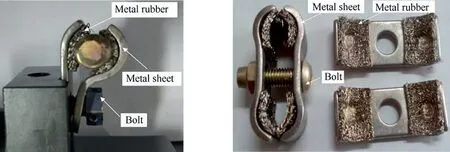
Fig. 19 Rigid clamps with metal rubber in aeroengine.
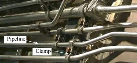
Fig. 20 Picture of clamps arrangement in aircraft.
The experiment had been conducted for analyzing the vibration of clamps under the base excitation.The base excitation was produced by the shaker driven by an amplified signal from vibration controller.Two pipeline with the same material and geometrical were investigated comparably. One of the pipeline was supported by bare clamp, and another was supported by viscoelastic pad clamp. The accelerator was placed at the surface of pipeline structure, as shown in Fig. 24. The test results showed that the pipeline with viscoelastic pad clamp could reduce the vibration significantly, as shown in Fig. 25. Moreover, compared with bare clamp, the pipeline with viscoelastic pad clamp could decrease the first order resonance frequency of pipeline system.
3.2. Optimum layout design of clamps
The hydraulic pipeline in aircraft suffers from serious vibration by pump fluid pressure pulsation, and the optimal layout of clamps is an effective method to reduce the vibration of hydraulic pipeline system.As discussed in Section 3.1,the stiffness of the clamp had obvious nonlinear characteristics due to the asymmetry of the structure and materials.However,for the vibration analysis of clamp-pipeline system, the stiffness of flexible clamp is usually assumed to be linear elastic in most studies. For the dynamic model of clamp-pipeline system, the clamp is commonly simplified as linear springs with an equivalent stiffness value. Many literatures have reported the linear equivalent stiffness method for clamps.In order to obtain the optimal design method of clamp layout, the number of clamps and the interval between clamps are considered as the constraints of layout optimization, and the optimization objective is commonly the pipeline natural frequencies or vibration response.
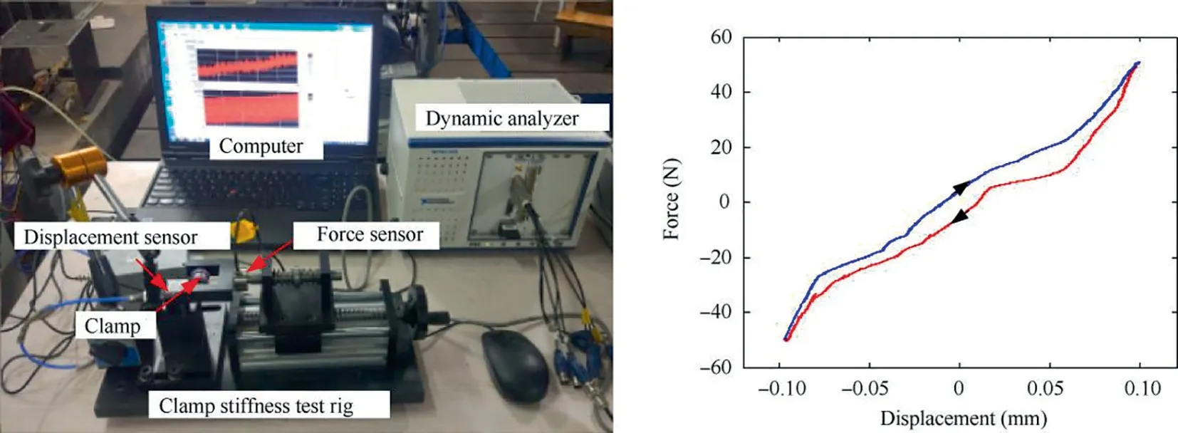
Fig. 21 Hysteretic loops of elastic-damping pipeline supports.
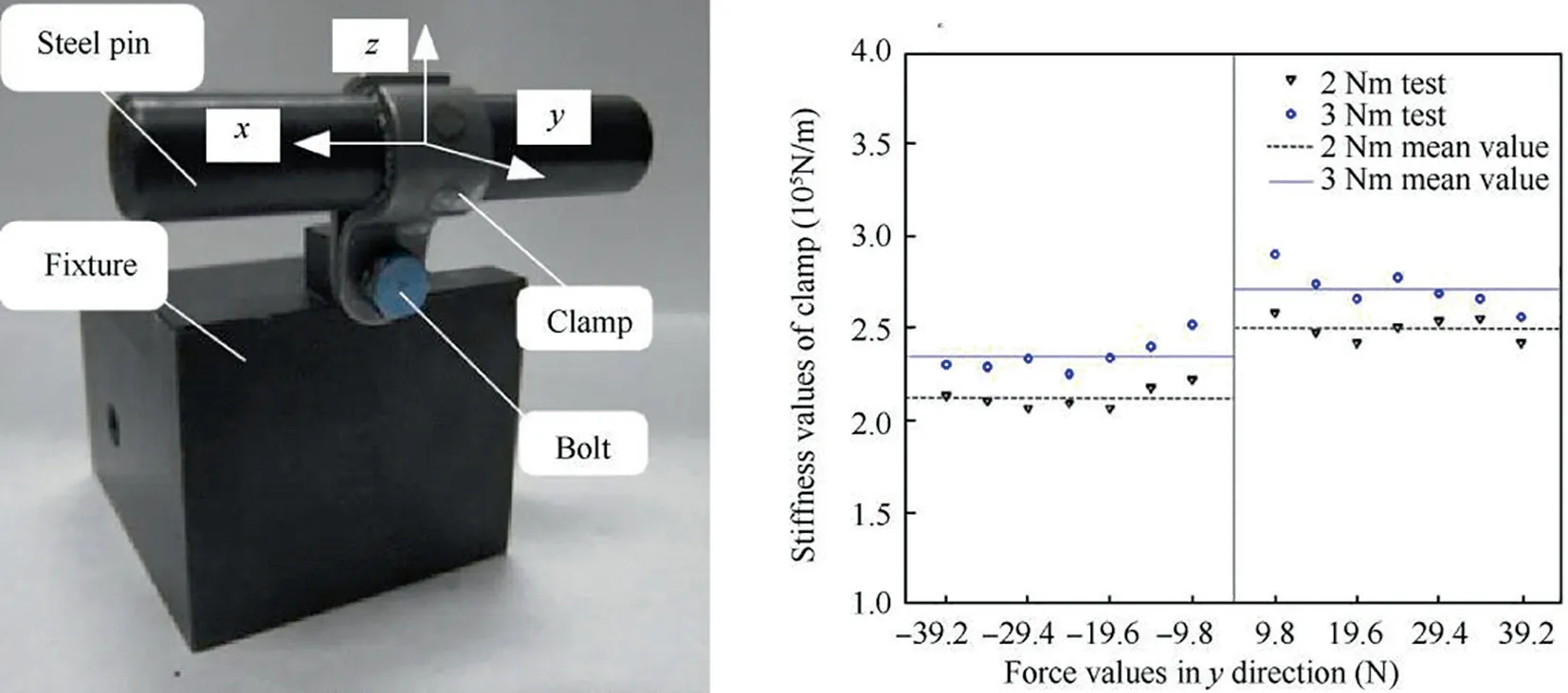
Fig. 22 Experimental set-up and translational stiffness of clamp in y direction.83
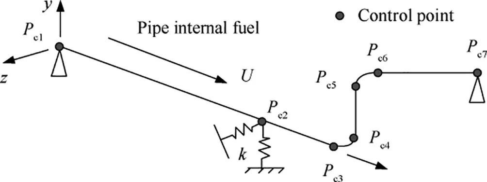
Fig. 23 Frequency response of pipeline for different support stiffness.85
Li et al.presented an optimum layout of hydraulic pipeline system in aircraft to reduce the vibration of pipeline, as shown in Fig. 26.The different scenarios were discussed to optimize the layout of hydraulic pipeline system. In order to avoid the harmful resonance and reduce the vibration stress of pipeline, a specific optimum method was proposed and the layout parameters were analyzed and optimized.Zhu and Zhangproposed a topology optimization method for layout optimization of supports. The optimization objective is to maximize the natural frequency of structures. Numerical result showed that the proposed method is effective for support layout design. Kwong and Edgeproposed a novel genetic algorithm method to reduce noise and vibration in hydraulic pipeline system. Experimental results showed that significant reductions in both noise and vibration had been obtained with the optimal clamp locations.
Tang et al.proposed an optimization model to reduce the vibration by designing the positions of clamps in hydraulic pipeline system,as shown in Fig.27.The results showed that the vibration performance of the hydraulic pipeline system was distinctly improved by the optimization procedure. The maximum displacement was reduced by 67.5%, and the maximum axial stress was decreased by 61.5%,which could provide reasonable guidance for the design of hydraulic pipeline system in aircraft.
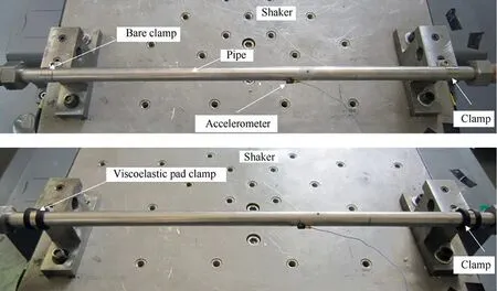
Fig. 24 Experimental set-up of pipeline with clamps.
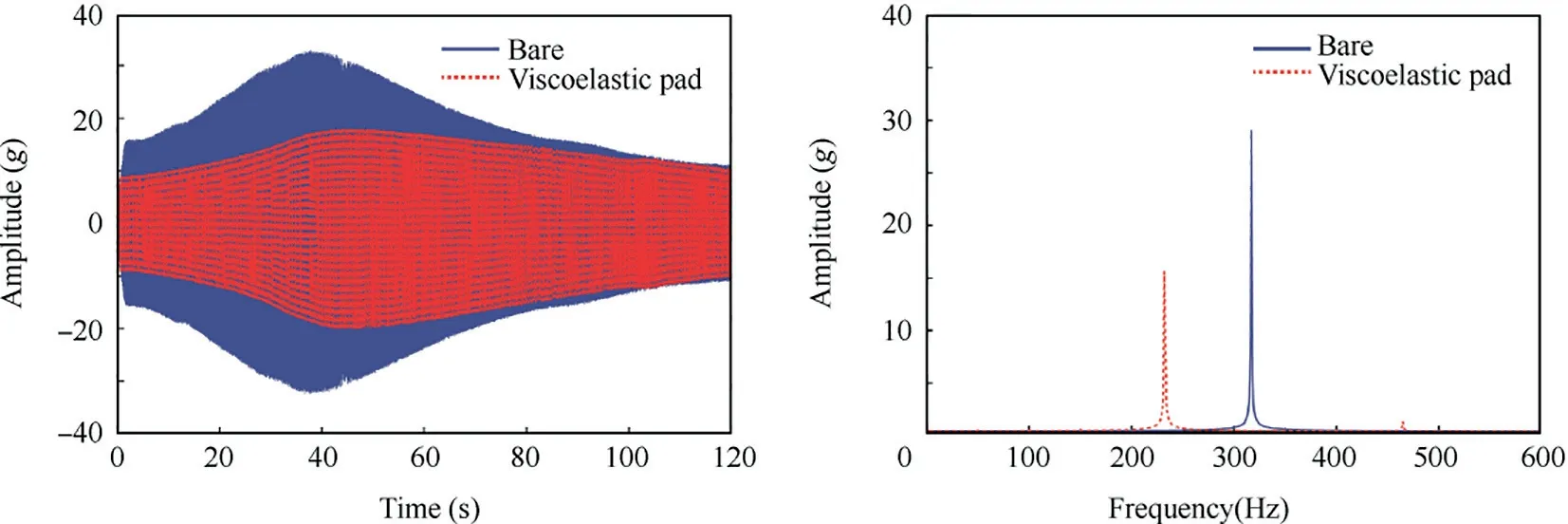
Fig. 25 Vibration response of pipeline with various clamps.
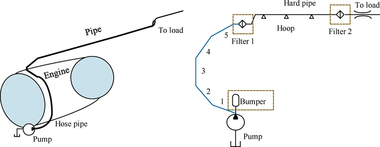
Fig. 26 Sketch of hydraulic power system in aircraft.87
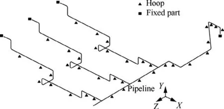
Fig. 27 A hydraulic pipelines system with clamps.91
Liu et al.investigated the sensitivity analysis and dynamic optimization design of support positions for aeroengine pipeline, as shown in Fig. 28.The parameters of l, l, l, l,l, lare the distances between the clamps, E is the elastic modulus of pipeline, Dis density of pipeline, Dis density of fluid,p is fluid pressure,s is stiffness of clamp,and t is temperature of fluid. The effect of clamps on the natural frequencies of pipeline were discussed. The optimal design of the clamp positions in complex pipeline system was carried by penalty function method. One of the optimization objective was the maximizing difference between fundamental frequency and external excitation frequency,and another was the minimizing mean square response of random vibration. Zhang et al.investigated the optimization design of clamps in aeronautical hydraulic pipeline system. Non-probabilistic sensitivity analysis is applied to eliminate clamps that were insensitive to the vibration response and natural frequencies of clamphydraulic pipeline system. Results showed that the vibration response of the pipeline system can be reduced significantly and after optimization.

Fig. 28 Fundamental frequency sensitivity diagram about design parameters.92
Gao et al.proposed a new optimization layout method for clamps in hydraulic pipeline system. The global sensitivity analysis was conducted to determine the effect of clamp position on the natural frequencies difference and vibration response, as shown in Fig. 29.A typical hydraulic pipeline was conducted to verify the effectiveness of the proposed method. Results showed that the maximum vibration stress of the hydraulic pipeline was reduced by 43.58%with the optimization of clamp layout. Chen and Zhupresented the genetic algorithm method to optimize the layout of the aeroengine pipeline system. The frequency and amplitude adjustment is defined as the optimization objective function for a typical pipeline. The calculation results showed that the proposed design method could acquire optimization solutions effectively. Zhou et al.investigated the sensitivity analysis for probabilistic anti-resonance design of aeronautical hydraulic pipelines.A global sensitivity index was proposed and it can provide a relatively new insight for anti-resonance design of aeronautical hydraulic pipeline.
As mentioned above, the optimal layout of clamps is an effective method to reduce the vibration of hydraulic pipeline system in aircraft. However, the stiffness of flexible clamp is commonly simplified as linear springs in literatures. In engineering field,with the increasing of the fluid pressure in aircraft hydraulic pipeline system, the vibration of pipeline become more serious,and the nonlinear clamp can make the vibration characteristic of pipeline more complex. Therefore, considering the nonlinear behavior of clamps for the optimal layout of pipeline is still challenging at present.It should be paid more attention to the optimal layout of hydraulic pipeline system for researchers in the future.
3.3. Constraint layer damping for pipeline system
The Constrained Layer Damping (CLD) materials are thoroughly used to control the structural vibration due to their high capacity to dissipate vibration energy. The constrained layer damping structure consists of three layers, as shown in Fig. 30. It is base pipeline layer, viscoelastic material layer and constraining layer. As the base layer was subject to the bending vibration, deformations of the viscoelastic material layer can be significantly increased between the base structure and constraining layer,and the constraining layer can enhance the damping capabilities.The constrained layer treatments are very reliable and they are extensively used in aerospace applications.
For hydraulic pipeline system in aircraft, the constrained layer damping material is an effective method to reduce the vibration of pipeline which is attached to the surface of the pipeline structure.A major advantage of the constrained layer damping treatment is the vibration reduction of pipeline resonance peaks without significantly altering the structural mass or stiffness.The common sketch of constrained layer damping material contains the protective paper, viscoelastic material and constraining material with thin metal.
The vibration and damping characteristics of CLD pipeline in aircraft was investigated based on developed finite element method.The thickness and the elasticity modulus of viscoelastic and constraining layer parameters were discussed.The results showed that the thicker viscoelastic layer as well as thinner constraining layer can improve the damping capability, as shown in Figs. 31 and 32.Moreover, an optimal value of the elasticity modulus for the viscoelastic and constraining layer can obtain the maximized damping performance. Bi and Haostudied the effectiveness of viscoelastic material to reduce the vibration of pipeline. The numerical analysis were carried out by commercial software ANSYS.The effects of various parameters were all discussed. Numerical results showed that the proposed method can be used to reduce the vibration of pipeline effectively by selecting the viscoelastic material and constraining layer properly. To attenuate pipeline vibration, a viscoelastic material was attached to pipeline and the added mass and damping method to address the effects of vibration of the damping material were investigated.The calculation results showed that the proposed method can match the measurement results closely. Ishikawa et al.designed a disc-shaped viscoelastic damping material attached to a pipeline as a dynamic absorber. The vibration of the pipeline was attenuated by the damping of viscoelastic material acting as dynamic absorber. The test results showed that the vibration response of pipeline were attenuated significantly by dynamic absorber.
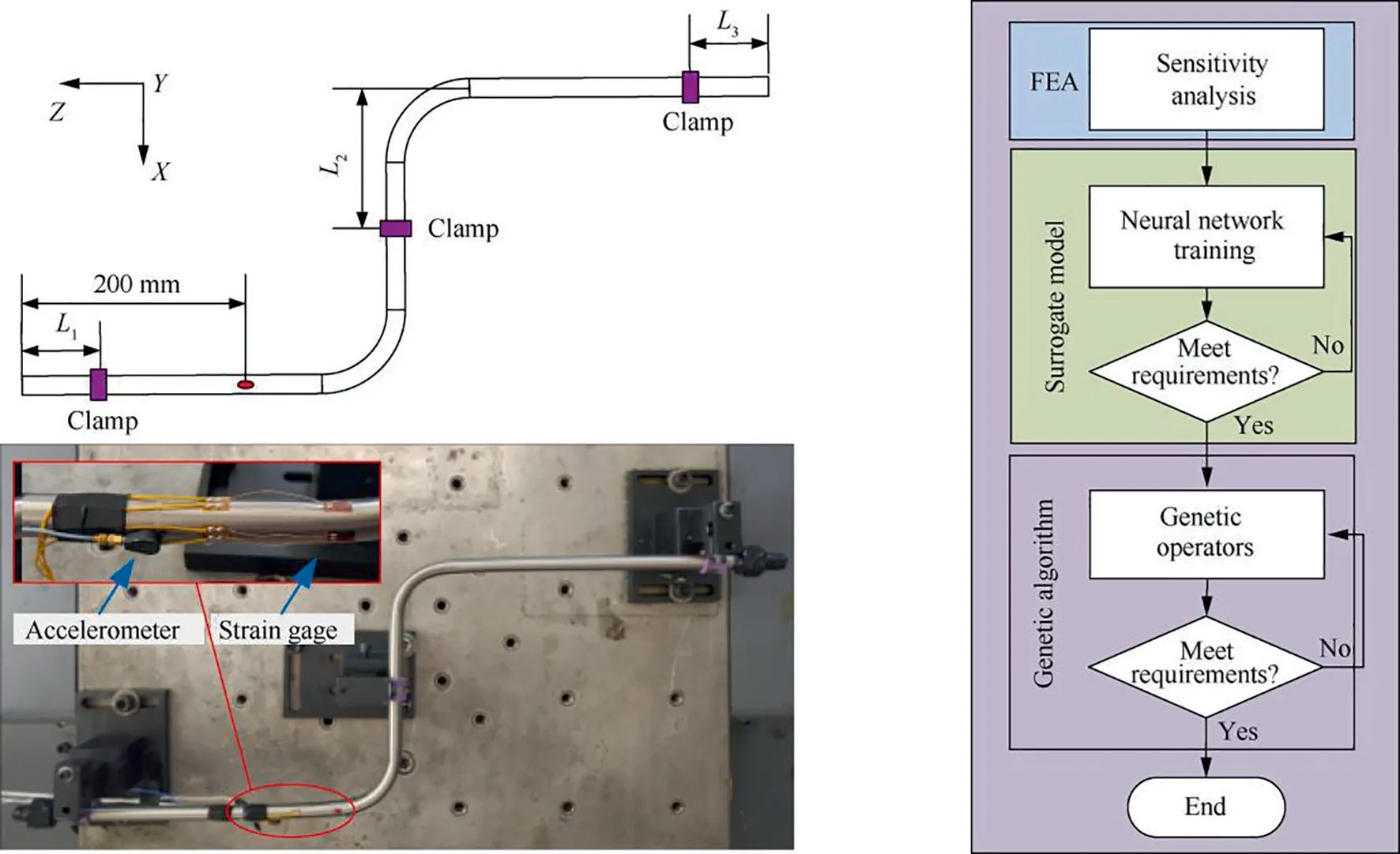
Fig. 29 Optimization layout method for clamps in hydraulic pipeline system.94
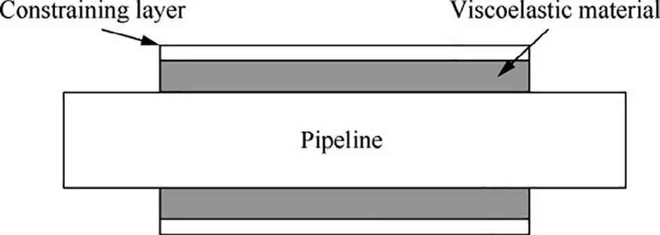
Fig. 30 Constrained layer damping structure.
In order to verify the effectiveness of pipeline with the constrained layer damping treatment,the experiment for hydraulic pipeline had been conducted under the base excitation. The base excitation was produced by the shaker driven by an amplified signal from vibration controller, and the excitation amplitude was 1 g. The type of the constrained layer damping material was Soundcoat DYAD 606, which was surrounded on the pipeline system. The accelerator was placed at the surface of pipeline structure,as shown in Fig.33.The test result of the vibration response in time domain and three dimensional waterfall under base excitation between bare and CLD pipeline were shown in Figs.34 and 35.It can be seen that the vibration response of pipeline decreased obviously when the constrained layer damping material was attached to the surface of pipeline structure. The vibration response amplitude decreased with 24.3% by attaching the constrained layer damping material on hydraulic pipeline system.
3.4. Vibration absorber for pipeline system
Vibration absorber is a passive vibration reduction method which can be easily installed on pipeline system. It consists of Tuned Mass Dampers (TMD), Particle Dampers (PD)and Hybrid Dampers (HD). Tuned mass damper consists of mass block and the linear spring, and its natural frequency is identical with the natural frequency of damped system. This method can only be effective when the natural frequencies of vibration absorber are the same as the working frequencies of pipeline. For different pipeline systems, their working frequencies are different,so it is very complicated to manufacture various vibration absorbers corresponding to their working frequencies. Particle damper is attached to the pipeline to reduce the vibration that uses the resonance characteristics to transfer the vibration energy of the pipeline system by additional mass and damping.Hybrid damper is an improved damper based on the mass-tunable damper and particle collision principle, which can provide a wider range of application for damper.
Yang and Zhangproposed a tuned mass damper to reduce the vibration of pipeline system based on antiresonance principle. A cantilever beam vibration absorber was designed to tune the natural frequency of pipeline, as shown in Fig.36.The vibration absorber of cantilever beam consisted of a mass block and a threaded cantilever rod. The absorber was connected with the pipeline by clamps. The vibration of the mass block caused the deformation of threaded rod, which can reduce the vibration of pipeline.
Zhou et al.designed a tuned mass damper with frequency adjustable, as shown in Fig. 37.The different frequencies can be obtained by moving the mass block on the leaf spring to reduce pipeline vibration.The finite element simulation and the vibration test results showed that the best damping effect of the dynamic vibration absorber can be obtained by adjusting the position of mass block on the leaf spring. Moreover, the pressure fluctuation frequencies can be reduced in all the directions. Jiang et al.conducted the experimental verification of a tuned mass damper for the vibration control of pipeline.Experimental results showed that the tuned mass damper was effective to reduce the vibration of pipeline at the tuned frequencies.
Yu et al.designed a particle damping absorber to reduce the vibration of pipeline in aircraft. The damping effect of the pipeline was improved based on the energy dissipation caused by particle collision. The designed absorber was installed on the surface of hydraulic pipeline system, as shown in Fig. 38.The test results showed that the vibration level of hydraulic pipeline under pump fluid pressure pulsation was significantly restrained by particle damper, which provided a new vibration control method for hydraulic pipeline system in aircraft.
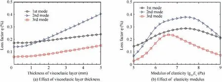
Fig. 31 Influence of viscoelastic layer for CLD pipeline.98
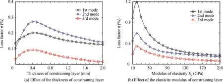
Fig. 32 Influence of constraining layer for CLD pipeline.98
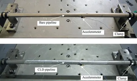
Fig. 33 Experimental set-up of pipeline with constrained layer damping treatment.

Fig. 34 Comparison of vibration response under base excitation in time domain between bare and CLD pipeline.
Yang et al.designed a hybrid damper based on the tuned mass damper and particle damper,as shown in Fig.39.The eight spring with identical stiffness was arranged symmetrically in the ring direction.The damping was induced by eight particle dampers attached to the outer ring. The radial stiffness of the spring system was calculated and the optimal tuning parameters of the damper were obtained by measuring the damping coefficient. The test results showed that the hybrid damper can suppress the pipeline structure vibration effectively in all directions with wide frequency range. Li and Tanginvestigated the vibration performance of a tuned mass particle damper. The dynamic model of the tuned mass particle damper was established based on the discrete element method. The calculation and test results showed that the proposed damper can effectively enhance the vibration suppression capability than common particle damper.
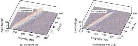
Fig. 35 Three dimensional waterfall of pipeline under base excitation between bare and CLD pipeline.
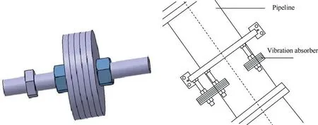
Fig. 36 A cantilever beam tuned mass dampers.102
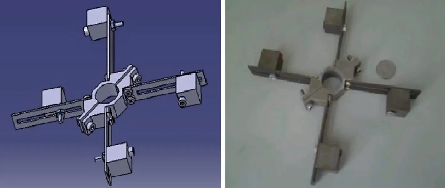
Fig. 37 A tuned mass dampers with frequency adjustable.103
3.5. Vibration absorber for hydraulic pipeline fluid
The fluid pulsation caused by the hydraulic pump in aircraft is the main source of the vibration and noise,therefore, the suppression of hydraulic fluid pulsation is a popular method to reduce the pipeline vibration.The installation of passive pulsation absorber(mainly attenuator)is the most practical solution to control pulsation of the hydraulic fluid system. The pulsation absorber of hydraulic pipeline has received considerable attention in the past years. Some striking achievements have been published in the open literatures.
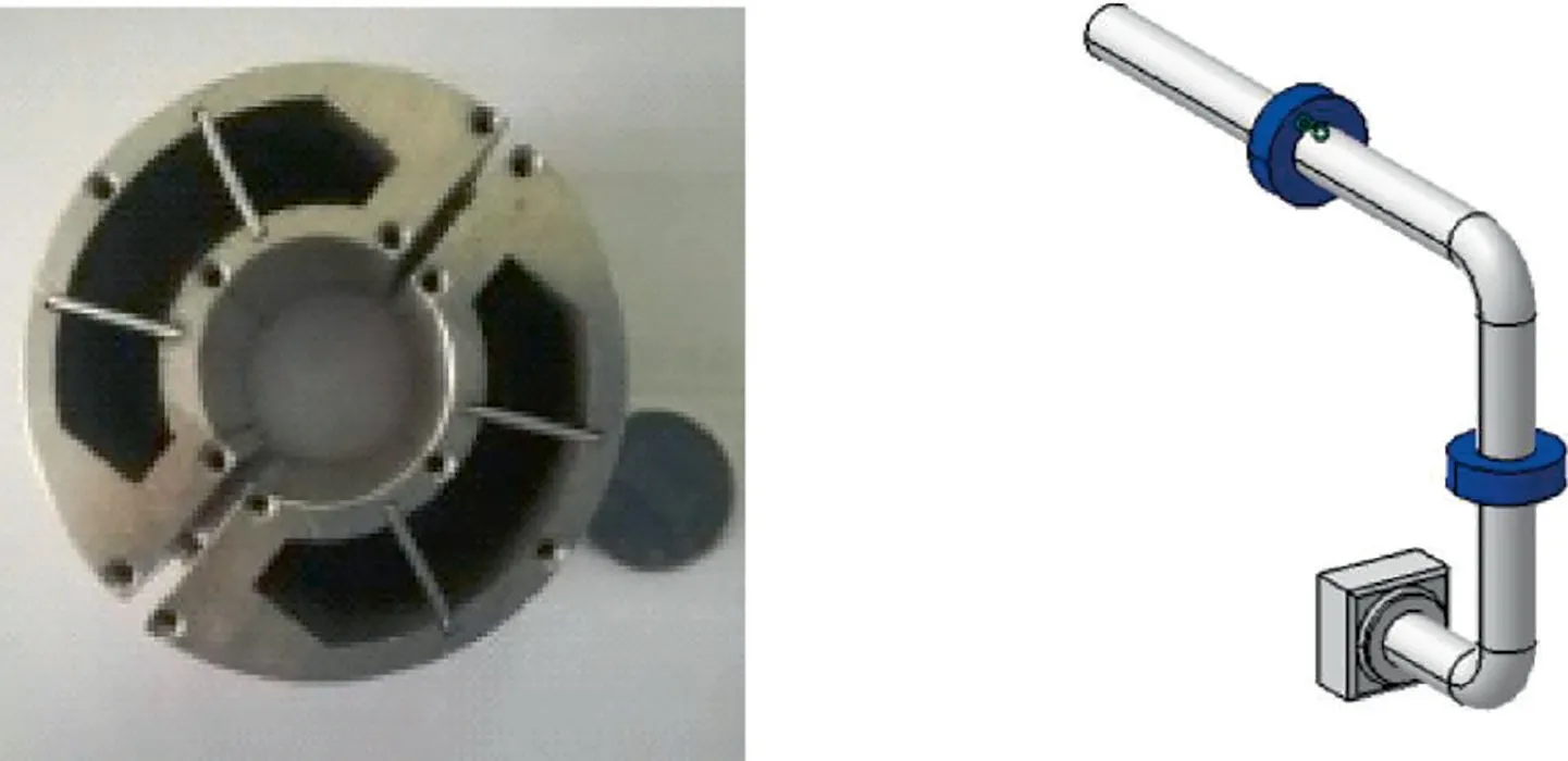
Fig. 38 A particle damping absorber of pipeline105
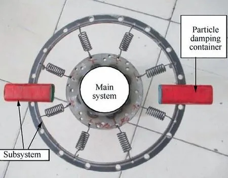
Fig. 39 Hybrid dampers based on tuned mass and particle dampers.106
The development of fluid fluctuation control technologies for aircraft hydraulic system were presented by researchers.In order to control the fluid pressure aircraft piston pump, a novel pulsation attenuator was designed and tested.As shown in Fig. 40(a),the attenuator reduced the higher instantaneous flow rate fluctuation by increasing the chamber volume,and the attenuator forced the oil back by reducing the high pressure chamber volume. Therefore, the corresponding volume change of the high pressure chamber can reduce the flow fluctuation. The photo of attenuator was shown in Fig. 40(b).The Attenuator location in the pump was shown in Fig. 40(c).The test results showed that the pressure fluctuation amplitude can be reduced by 80%, as shown in Fig. 40(d).
Chai et al.designed a new hydraulic fluctuation attenuator that embedded in the hydraulic piston pump, as shown in Fig.41(a).It consisted of pump body(1),compact attenuator (2), gas charging valve (3), pump’s valve plate outlet (4)and an inner tunnel to pump outlet (5). The rubber bladder was compressed to reach a higher pressure with the working of hydraulic pump, which was the same as system pressure.Therefore, the compact attenuator can suppress the pressure fluctuation by the compressibility of the rubber bladder. The photo of attenuator and testing device were shown in Fig. 41(b)and Fig.41(c).Test results showed that the attenuator can absorb the flow ripples with 35%reduction in the hydraulic system, as shown in Fig. 41(d).
The application of pressure pulsation attenuator, accumulator, Helmholtz resonator, and other pipeline pulsation suppressor in hydraulic system were studied theoretically and experimentally. The characteristics of different types of pulsation attenuators to reduce pressure pulsation were obtained.Typically,a novel compact pulsation compensator to reduce pressure pulsations in hydraulic system was proposed by Mikota,as shown in Fig.42.The attenuator was connected to the main hydraulic system (1). The working piston (3) with mass block was excited by the pressure pulsation in the main hydraulic system. The experimental results were in good agreement with the simulation results.The results showed that the pressure pulsation in the main hydraulic system could be attenuated by -30 dB with the attenuation frequency range [10 220] Hz.
3.6. Other passive vibration control methods
For the aircraft hydraulic system, many other passive vibration control methods are proposed in the open literatures.Such as the hydraulic hose method, the surge flask integrated on the pump method, and the optimizing hydraulic pump internal structure method, etc.
The hydraulic hose is usually installed at outlet of the aero hydraulic pump in order to decrease the fluid pulsation and the structure vibration from the pump casing. Tucinvestigated the effectiveness of flexible hoses for decreasing pressure fluctuations in a hydraulic pipeline system. A developed model for calculating pressure fluctuation in hose pipeline was proposed. The theoretical and experimental results showed that the short length of hose can reduce pressure fluctuations at a particular frequency, and the long length of hose can reduce pressure fluctuation at broadband attenuation. Longmore and Schlesingerstudied the transmission relationships between the vibration and pressure fluctuation through hydraulic hose theoretically and experimentally. Johnstonproposed a time-domain method to solve complex interactions between the liquid and the hose wall, good agreement was obtained between the model and test result.Li and Fandiscussed the installation of hose for hydraulic pipeline systems in aircraft. The hydraulic pump can produce serious pressure fluctuation,and the pump outlet need to be designed as a hose connection to reduce the fluid pulsation and the pipeline structure vibration.The hydraulic hose installation design criterion was concluded, and a typical hydraulic hose installation aircraft was conducted, as shown in Fig. 43.
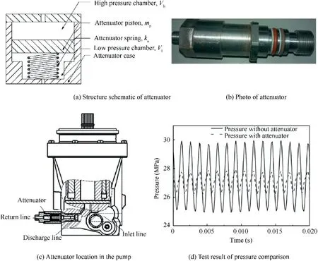
Fig. 40 A novel pulsation attenuator for pressure-controlled aircraft pump.110
In addition to the fluid pulsation attenuators mentioned above, the surge flask integrated on the pump was also a very important attenuator.Considering the reduction of pressure fluctuation,the engine driven pump integrated surge flask was used in Airbus A380, as shown in Fig. 44.The results showed that the pressure fluctuation amplitude of hydraulic pump integrated surge flask can be reduced to ±1%. Guo and Luinvestigated the mechanism of pressure fluctuation for hydraulic system. The hydraulic pump was the source of pressure pulsation, and various methods to suppress the pressure pulsation were presented. Results showed that the surge flask integrated on the pump was an effective method to reduce pressure fluctuation in application.
Moreover, optimizing the hydraulic pump internal structure can also reduce the pressure fluctuation of hydraulic system. Such as the optimizing design of valve plates and swash plates.Seeniraj et al.investigated the effectiveness of several passive design methods for valve plates. Results showed that the precompression grooves and precompression filter volume were the most effective method for reducing the pressure fluctuation in hydraulic pump.Based on the matching of flow area and the reduction of transient reverse flow, a new design method was proposed by Xu et al.for valve plates in hydraulic pump. Results showed that the proposed method could reduce the fluid fluctuations significantly. Manring and Dongstudied the control and containment forces acting on the swash plates of hydraulic pump. Results showed that the pressure fluctuation can be reduced by implementing a secondary swash plate angle that reduced the overall control effort of the pump.
4. Active vibration control technologies for pipeline system
For active vibration control,the pipeline vibration response is controlled by adding an external effort to the structure. This technique typically consists of the sensor, controller and actuator. The sensor is used to detect the vibration of pipeline,actuator can change the vibration response of pipeline, and the controller can acquire the signal from sensor and reduce the pipeline response according to the requirement.In general,sensors and actuators are made of piezoelectric materials.When the piezoelectric actuators and sensors, are either attached on or inserted into the pipeline structure,the pipeline can have the self-sensing and controlling abilities.
For hydraulic pipeline in aircraft, the pipeline suffers from serious vibration by fluid pressure fluctuation of hydraulic pump and base excitation of aeroengine working environment,the active vibration control technologies can be implemented as follows:
(1) Active vibration control of hydraulic pipeline fluids.
(2) Active vibration control of pipeline structures.
(3) Active vibration control algorithms.
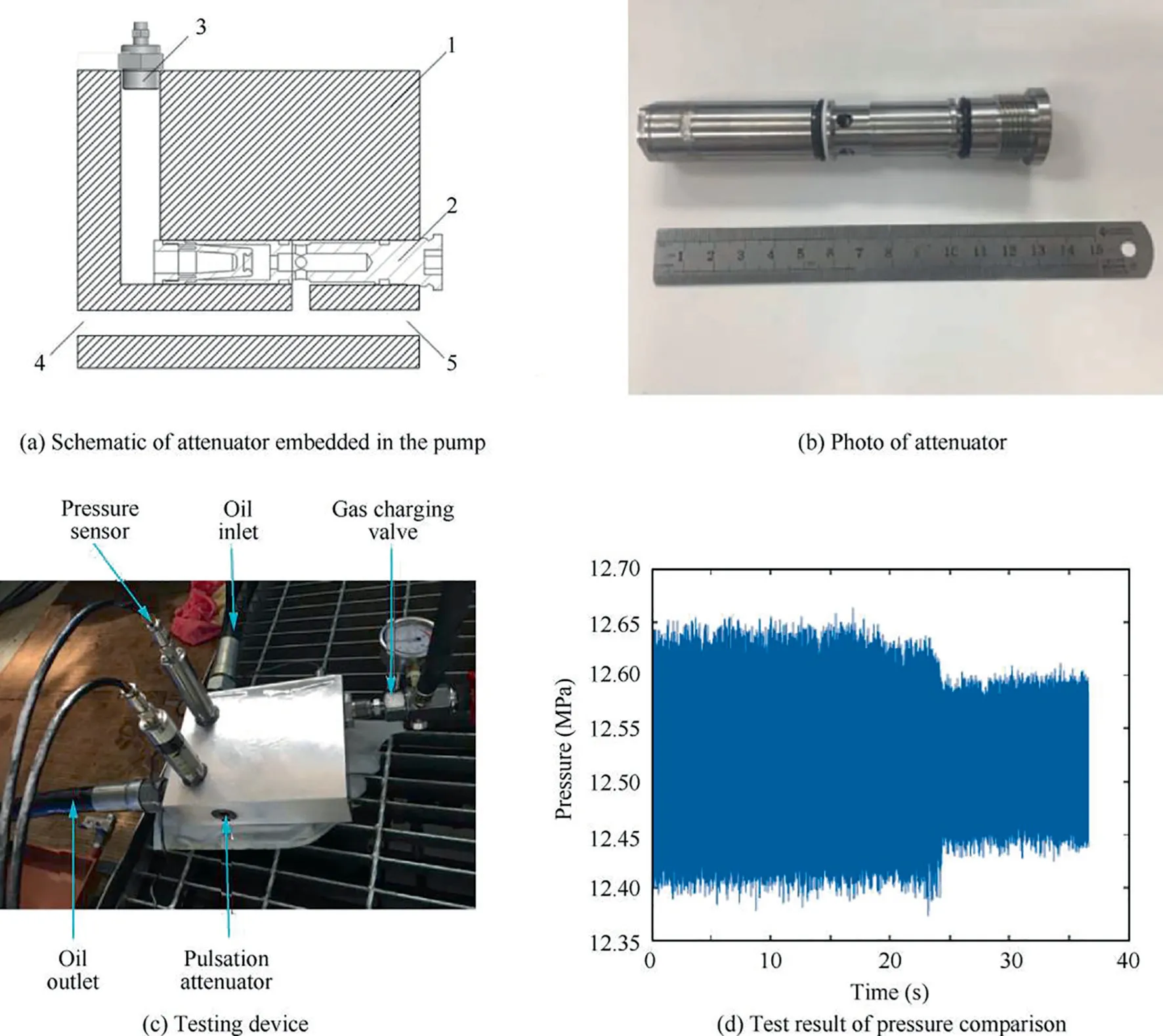
Fig. 41 A new design of pulsation attenuator for hydraulic pump.111
4.1. Active vibration control of hydraulic pipeline fluids
In order to reduce the fluid pressure pulsation of hydraulic pipeline system, the active vibration control method is proposed in which the secondary pressure pulsation wave with phase difference of 180 degree is usually superimposed with the primary pressure pulsation wave produced by pump source system to eliminate the pressure pulsation in hydraulic pipeline.Generally, there are three methods to generate secondary pressure fluctuations. One is to generate pressure pulsation wave by servo valve, the other is to install servo actuator in the pipeline to increase or decrease the pipeline volume by controlling the reciprocating motion of servo actuator cylinder,so as to generate pressure pulsation wave to offset the pressure pulsation of the original system.The last one is that piezoelectric ceramics materials act directly on the pipe wall and produce pressure pulsation wave through the deformation of the pipe wall, thus counteracting the pressure and flow pulsation in the pipeline.
The development of the active control technologies of hydraulic fluid fluctuation was presented by Li and JiaoA comprehensive review of the reduction fluid fluctuation was conducted and all kinds of vibration control strategies were discussed by KarthaFor active control of hydraulic fluid pulsation, a new servo actuator was proposed and designed as secondary pulsation source. The pressure pulsation collected by pressure sensor installed upstream of pipeline as feedback control, and the different signals produced by two pressure sensors installed behind servo actuator.The test results showed that when the new servo actuator operated, a transmission loss of 20-25 dB can be obtained at the frequency range of[20 250]Hz.Luo et al.proposed a semi-active accumulator to absorb flow and pressure pulsation.Simulation and experiment results showed that semi-active accumulator can absorb pressure pulsation better than by passive accumulator.
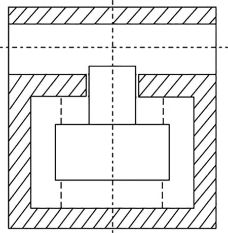
Fig. 42 A novel compact pulsation compensator to reduce pressure pulsation.119
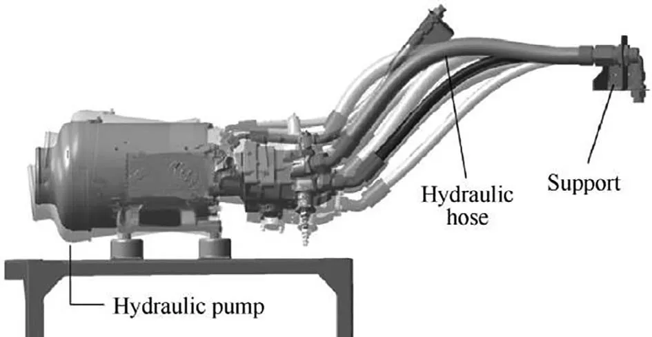
Fig. 43 A hose accounts for hydraulic systems in aircraft to reduce fluid pulsation.123
Guan et al.proposed a novel Active Control of Fluid Pressure Pulsation (ACFPP). A Piezoelectric Direct-Drive Slide Valve (PDDSV) was designed as the active vibration absorber,as shown in Fig.45.The spool-driving mechanism consisted of a preloaded piezoelectric actuator,a spool, a disk spring rod, and a driving disk spring, and the PDDSV was adjusted by the piezoelectric actuator. An adaptive-optimum control method was proposed to adjust the control parameters in order to minimize the amplitude of the fluid pressure pulsation. The simulation and experiment results showed that the proposed ACFPP can reduce the fluid pressure pulsation significantly. Jiao et al.discussed the vibration active control methods to reduce the vibrations of fluid power supply and piping systems. A new vibration active control method with multilayer piezoelectric technology driven orifice valve was proposed to reduce the vibrations of the fluid pulsation.The test results showed that this method was capable of reducing the vibrations at a minimum level.
Pan et al.presented an active adaptive noise control method for reducing pressure pulsation in hydraulic system.A high-performance piezoelectric valve was used as the secondary path actuator in terms of its fast response and wide bandwidth. The schematic diagram of active control system was shown in Fig. 46.The prototype of the piezoelectric actuated valve was shown in Fig. 47.The flow rate can be modulated by adjusting the distance between the moving plate and the stationary plate, and the valve was directly activated by a piezoelectric actuator to achieve a fast dynamic response.The test results showed that the controller was capable of performing robustly with changing conditions and it could be applied to much higher pressure in hydraulic system.
Another active method is fluid-wave actuator acting on the pipe wall outside the pipeline and producing pressure pulsation wave through the deformation of the pipe wall. Brennan et al.designed the non-intrusive fluid-wave actuator to control fluid-borne vibration in pipeline system, as shown in Fig. 48.The cross-section of the fluid-wave actuator was manufactured and fitted to the water-filled pipeline using epoxy resin.The sensor was made of piezoelectric elements fitted around the outer circumference of the pipeline.Test results showed that the actuator can suppress the fluid-wave with the reduction amplitude of 20 dB at the frequency range 10-1000 Hz.Maillard et al.designed a non-intrusive fluid wave actuator to control the fluid pressure pulsation. The actuator consisted of a circumferential ring of PZT stacks acting on the pipe outside wall to generate an axisymmetric plane wave in the fluid. Experimental results showed that the actuator can be used in hydraulic pipeline system for fluid pressure control.
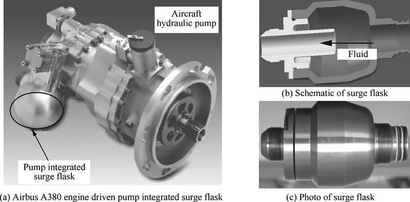
Fig. 44 Aircraft hydraulic pump integrated surge flask.125
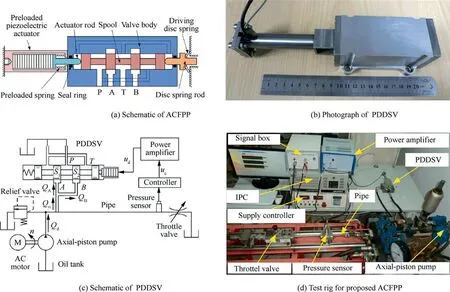
Fig. 45 A new novel active control of fluid pressure pulsation (ACFPP).136
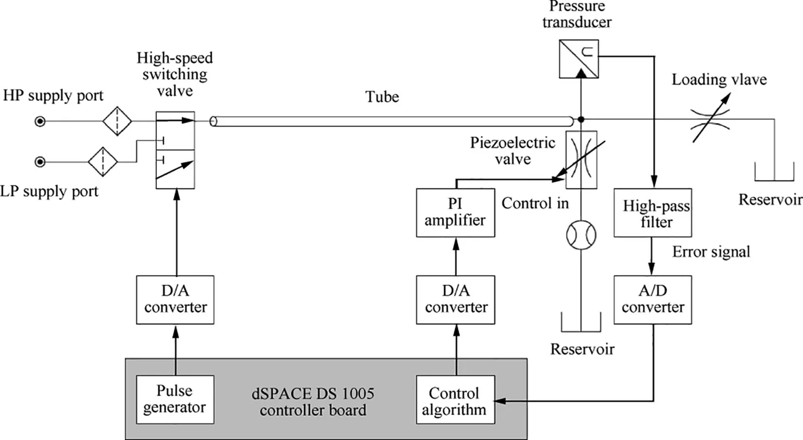
Fig. 46 Schematic of bypass structure based on a flow booster system with noise attenuator.140
4.2. Active vibration control of pipeline structures
Active vibration control method employs an external force to modify the deformation of pipeline structure in desired way.Actuators are usually made of piezoelectric materials with compact and simple characteristics. Active Constrained Layer Damping(ALCD)involved using the piezoelectric actuator to control the strain in constraining layer.The pipeline structure vibrations can be suppressed by the piezoelectric actuator force and the enhanced damping by the increased deformations in viscoelastic layer was shown in Fig. 49.
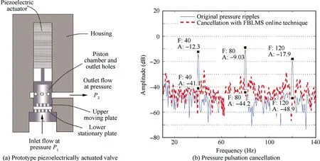
Fig. 47 Active control of pressure pulsation in hydraulic system.140
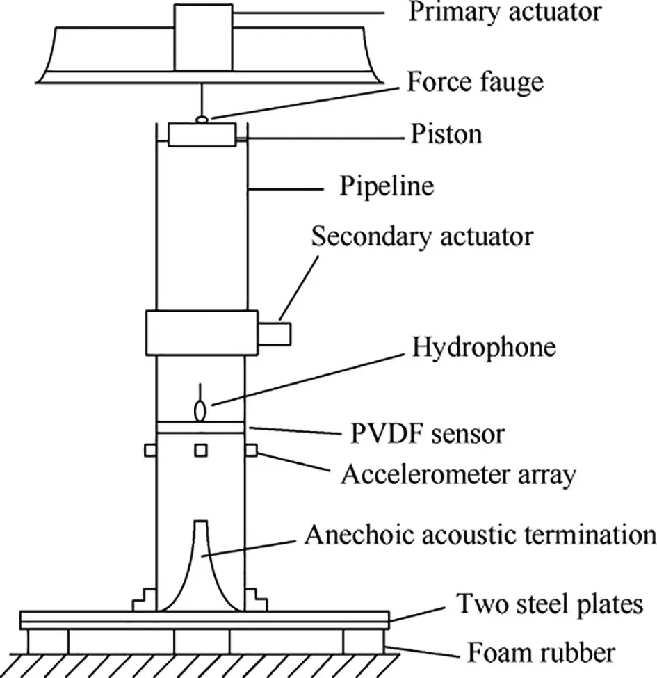
Fig. 48 Fluid-wave actuator in hydraulic system.143
Active control technology of pipeline structure was to obtain vibration information of pipeline by sensor, and then control the vibration of pipeline by actuator.The piezoelectric ceramics were employed as the actuators to suppress the vibration of long slender cantilever pipeline,as shown in Fig.50.Xr is the distance of piezoelectric actuator,tis the thickness of actuator, rand rare the pipeline inner diameter and outer diameter. θ and β are the angles of piezoelectric actuator. An optimal independent model space control method was applied to suppress the instability of the pipeline. Numerical results showed that the vibration of the cantilever pipeline can be effectively suppressed by a moderate driving control voltage fed into the piezoelectric actuators.Doki et al.designed the controller by an algorithm to control the vibration of cantilevered pipeline.The theoretical and experimental results showed that the controller can suppress the vibration of cantilevered pipeline conveying fluid effectively.Elvin NG and Elvin Ainvestigated the cantilever pipeline with resistive piezoelectric damping.Numerical results showed that the addition of piezoelectric ceramics can either increase or decrease stability of the system depending on the piezoelectric parameters and the attached electrical load resistance.
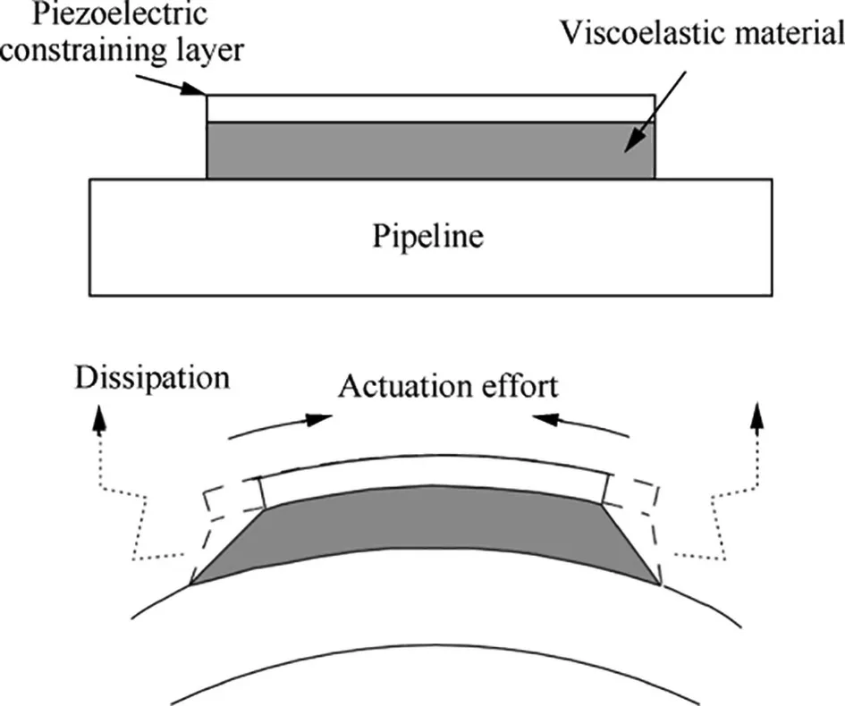
Fig. 49 Active constrained layer damping.97
Active constrained layer damping involved using the piezoelectric actuator to control the strain in constraining layer,and the vibration of a flexible pipeline was controlled by ACLD bonded to the pipeline surface.The pipeline vibration was controlled by the ACLD patch using a simple velocity feedback controller. Experimental and theoretical results showed close agreement.Wang et al.discussed the length and location of active constrained layer damping for vibration control of shell structure. Panda et al.proposed an improved active constrained layer damping through the design of a viscoelastic composite material. The ACLD with the shell-surface was ensured by a vertically reinforced 1-3 piezoelectric composite constraining layer. The theoretical results revealed significant improvement of the ACLD by 1-3 viscoelastic material layer.

Fig. 50 Cantilever pipeline with piezoelectric actuators.145
Zhai et al.investigated the vibration control of an aero pipeline system by active constrained layer damping treatment.The vibration control system consisted of signal feedback sensor,controller,piezoelectric actuator,acceleration sensor,data acquisition system, and computer, as shown in Fig. 51.When the pipeline was deformed, the piezoelectric ceramics would be deformed, and the electric charge can be generated on the surface of the piezoelectric ceramics. The data acquisition system collected the voltage and calculated the output control signal by the controller. The inverse piezoelectric restraint layer was utilized to produce the corresponding deformation on the surface of the pipeline.Vibration signal of pipeline was collected by acceleration sensor,and it transmitted to computer through data acquisition system. For a typical aero hydraulic pipeline, experiment results showed that the vibration response amplitude under base excitation decreased significantly.
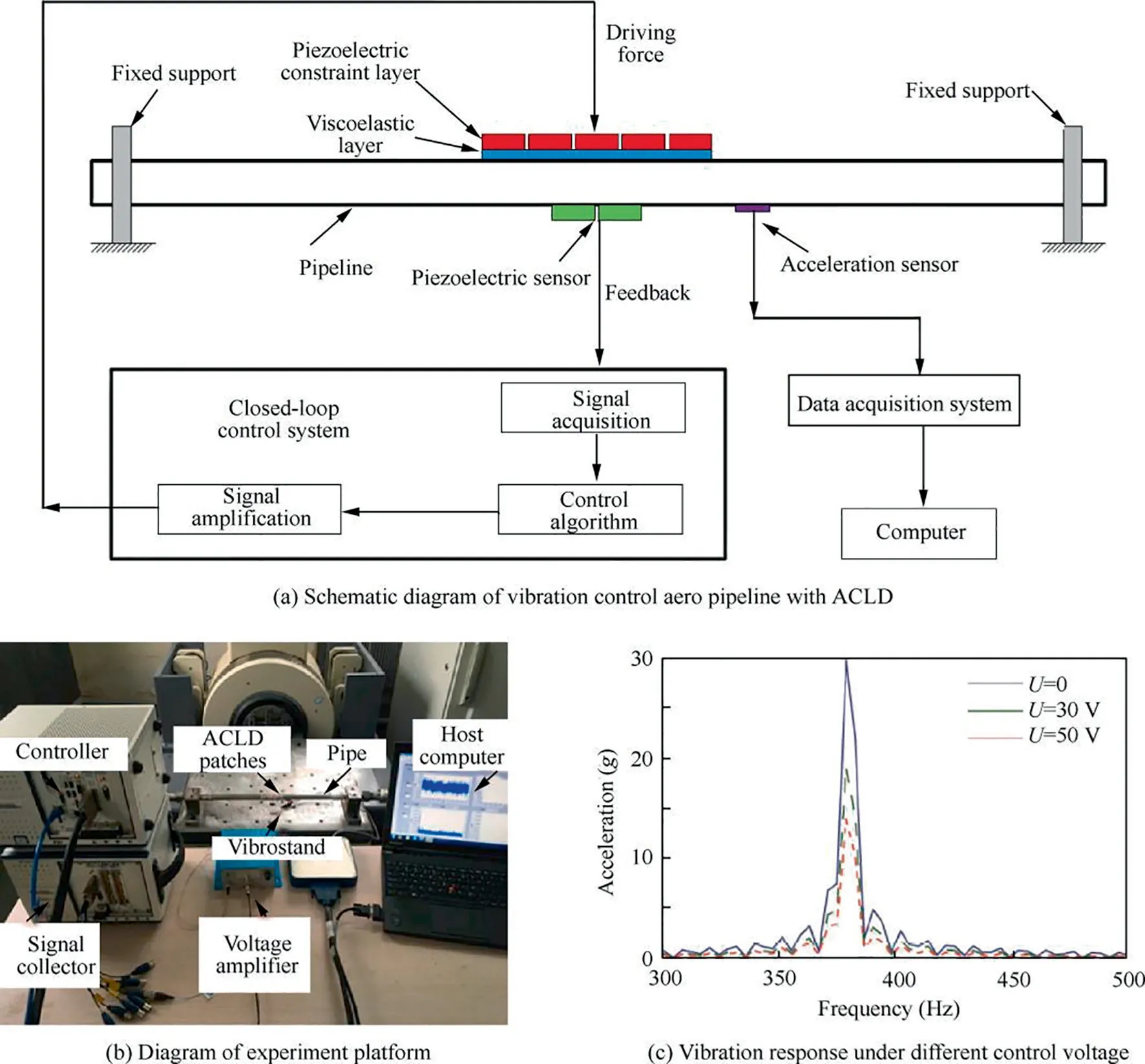
Fig. 51 Vibration control of aero pipeline system by active constrained layer damping.153
4.3. Active vibration control algorithms
For active vibration control,the control effect is closely related to the control method and algorithm. The common control algorithms in the open literatures are adaptive control algorithm, adaptive-optimum control algorithm, neural network control algorithm, and fuzzy control algorithm, etc.
The adaptive control algorithm of active vibration control was mainly based on the feedforward control and feedback control of adaptive filter.The main adaptive control algorithm was the Filtered-x Least Mean Square (FXLMS). Maillard et al.designed a FXLMS control algorithm to generate an axisymmetric plane wave in the fluid for controlling the fluid pressure. Experimental results showed that the FXLMS control algorithm can reduce the fluid pulsation significantly.Pan et al.proposed an adaptive notch filter with a variable step-size FXLMS control algorithm in the new designed active piezoelectric actuator. The results showed that the FXLMS algorithm can be a fast convergence speed of the active attenuator,and the presented control method can effectively reduce fluid pressure pulsation in wide frequency range, as shown in Fig. 52.
Adaptive-optimum control algorithm refers to the pressure pulsation of the system that can be actively attenuated to minimize the sum square of the pressure amplitude by automatically adjusting the amplitude, frequency and phase of the input signal. Jiao et al.presented the adaptive-optimum control method to reduce the fluid pulsation vibration by adjusting the control parameters automatically. The test results showed that the adaptive-optimum control algorithm had many advantages of strong adaptability and robustness characteristics. Ouyang et al.used the adaptive-optimum control algorithm to reduce the vibration of hydraulic pipeline system by piezoelectric direct valve. The vibration active control method was adaptive and robust against disturbance.The simulation results showed that adaptive-optimum control algorithm can adjust control parameters at any time against the disturbance.
Neural network control algorithm is trainable system with the ability of self-learning and self-adaptive abilities. The neural network control algorithm can be applied to the active control of hydraulic fluid pulsation by properly selecting the network type and network parameters.Alyproposed a neural network control algorithm to control the pump flow rate.The trained neural network based on the conventional PID controller was applied to the control of swash plate displacement. The results showed that the neural network algorithm had the advantage of robustness and independent of system parameters. Ji et al.used the neural network algorithm to adjust the controller parameters. The piezoelectric throttle valve generated the secondary pulsation to offset the initial pulsation. The results showed that the active control method by neural network can reduce the fluid pulsation amplitude significantly. In addition to the control algorithms mentioned above, the fuzzy control algorithm,the PID control algorithm,robust control algorithm,nonlinear energy sink algorithm,had been applied to realize the active control of hydraulic pipeline system.
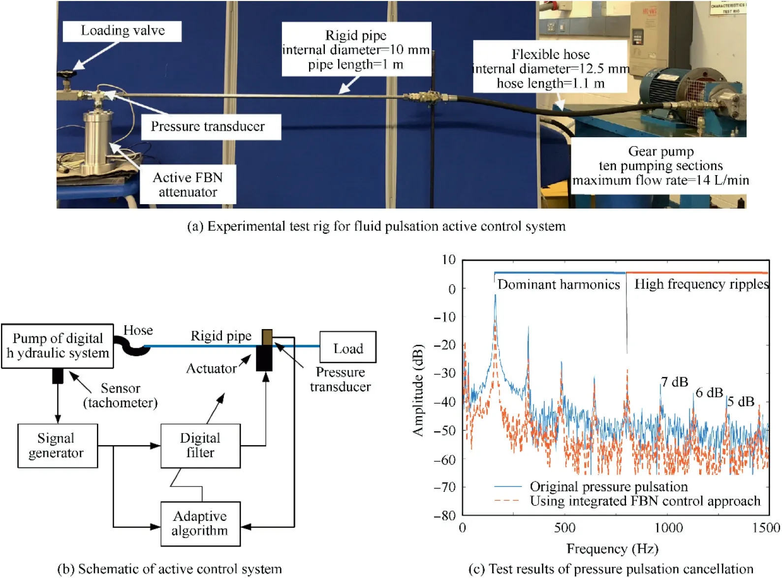
Fig. 52 Active fluid control system of adaptive notch filter with a variable FXLMS control algorithm.155
For hydraulic pipeline in aircraft,the passive vibration control technologies have the advantages of simple installation,easy operation and good suppression effect on high vibration frequency. The active control technologies are characterized by strong follow-up, dexterous action, strong adaptive ability,and good suppression effect on low vibration frequency.However, the cost of active control technologies are higher than passive control technologies, and there are many closed-loop control system links in which a risk of failure in each link can occur. For the application of active control technologies in aircraft, it is necessary to improve the reliability of active control technologies in engineering application.
5. Conclusions
In this paper, the research progress of vibration analysis and control technologies of hydraulic pipeline system in aircraft are reviewed. The vibration mechanism of pipeline system,vibration fault mechanism, active and passive vibration control technologies of pipeline system are summarized respectively. Among them, the vibration control technologies of pipeline system are emphatically reviewed, including the high damping support clamp, optimum layout design of clamps,constraint layer damping for pipeline system, vibration absorber for pipeline system, hydraulic hose, optimal pump structure, and the active vibration control technologies of pipeline system. Combining with the structure and load characteristics of aircraft hydraulic pipeline system, this paper gives the following suggestions for vibration control and engineering applications of pipeline system.
(1) In the future, the pressure of hydraulic pipeline system in aircraft will further develop along the trend of high fluid pressure.The intensity of fluid pressure fluctuation is greater, and the pipeline vibration caused by pressure fluctuation is more serious.Higher requirements are put forward for the design of pipeline system. In the design process, it is necessary to consider avoiding pipeline faults such as excessive vibration, vibration fatigue and seal failure. In order to meet the requirements of strength and life,the reliability index should be satisfied to a strict extent. Compared with the high pressure pulsations, the low pressure pulsations inside the pipeline can cause the bubbles and cavitation that can have great impact on the performance of hydraulic system. It is more complex and dangerous to the hydraulic pipelines and it should be paid great attention for the design of pipeline systems in aircraft.
(2) The development of high fluid pressure in aircraft has challenged the vibration control technologies of hydraulic pipeline system. Passive vibration control technologies of pipeline system can reduce the vibration level of pipeline system significantly. Future research focuses on the nonlinear dynamic characteristics of highdamping clamps, optimization clamp layout, effective vibration absorber for pipeline system and optimization high-damping viscoelastic materials layout of pipeline system. In the practical application of engineering, it is necessary to consider the factors such as installation technology and operation reliability of damping materials.
(3) Active vibration control technologies of hydraulic pipeline system in aircraft are the development direction of vibration reduction technologies in the future. The load excitation frequency range of pipeline system in aircraft is wide, the passive vibration reduction technology has fewer effect in low frequency range, and the vibration reduction effect is obvious in high frequency range.The active control technologies can realize the effective control of low frequency,and they have strong adaptive ability, flexible design and good controllability characteristics. In the practical application of engineering,there are many links in closed-loop control system, the reliability for active vibration control technology needs to be further improved due to the risk of failure in each links.
Generally speaking,the vibration characteristics and vibration control technologies of hydraulic pipeline system in aircraft have attracted considerable attention in past decades,and some striking achievements have been achieved.However,from the engineering application point of view, due to the complexity of pipeline structure and load excitation, effective vibration control technologies are urgently needed to be proposed for the vibration suppression of pipeline system under multi-source excitation in wide frequency domain. It should provide technical guidance for the design and maintenance of hydraulic pipeline system, and establish design criteria for hydraulic pipeline system in aircraft.
Declaration of Competing Interest
The authors declare that they have no known competing financial interests or personal relationships that could have appeared to influence the work reported in this paper.
Acknowledgement
This study was supported by the National Natural Science Foundation of China (No. 51805462).
 CHINESE JOURNAL OF AERONAUTICS2021年4期
- CHINESE JOURNAL OF AERONAUTICS的其它文章
- Time delay compensation in lateral-directional flight control systems at high angles of attack
- Dual stability enhancement mechanisms of axial-slot casing treatment in a high-speed mixed-flow compressor with various tip clearances
- Development cost prediction of general aviation aircraft using combined estimation technique
- Improvement on shaped-hole film cooling effectiveness by integrating upstream sand-dune-shaped ramps
- Modeling and parameter identification of linear time-varying systems based on adaptive chirplet transform under random excitation
- An experimental method to obtain the hard alpha anomaly distribution for titanium alloy aeroengine disks
