Improvement on shaped-hole film cooling effectiveness by integrating upstream sand-dune-shaped ramps
Shengchang ZHANG, Jingzhou ZHANG, Xiaoming TAN
College of Energy and Power Engineering, Key Laboratory of Thermal Management and Energy Utilization of Aircraft,Nanjing University of Aeronautics and Astronautics, Nanjing 210016, China
KEYWORDS Adiabatic film cooling effectiveness;Film cooling;Numerical simulation;Sand-dune-shaped ramp;Shaped hole
Abstract A numerical investigation and experimental validation is performed to address deeper insights into the combined effect of shaped holes and Sand-Dune-shaped upstream Ramp (SDR)on enhancing the film cooling effectiveness, under a wide blowing ratio range (M=0.25-1.5).Three kinds of holes (Cylindrical Hole (CH), Fan-Shaped Hole (FSH), and Crater-Shaped Hole(CSH)) are taken into consideration. The SDR shows an inherent affecting mechanism on the mutual interaction of jet-in-crossflow. It aggravates the lateral spreading of cooling jet and thus improves the film cooling uniformity significantly, regardless of film-hole shape and blowing ratio.When the blowing ratio is beyond 1.0,the combined effect of shaped holes and SDR on improving film cooling effectiveness behaves more significantly.It is suggested that FSH-SDR is a most favorable film cooling scheme. For FSH-SDR case, the spatially-averaged film cooling effectiveness is increased monotonously with the increase of blowing ratio,among the present bowing ratio range.©2020 Chinese Society of Aeronautics and Astronautics.Production and hosting by Elsevier Ltd.This is an open access article under the CC BY-NC-ND license(http://creativecommons.org/licenses/by-nc-nd/4.0/).
1. Introduction
The high-performance aero-engine requires the compressor pressure ratio and turbine inlet temperature further prompted.Operating in such a severe aero-thermal environment,the hotsectional components must face to a critical problem associated with their effective thermal protection.Undoubtedly,high-efficient cooling technology is one of the key technologies in the development of advanced aero-engines.
Film cooling technique plays a major role in the thermal protection of turbine hot-section components. In practical applications,the discrete-hole film cooling is mostly concerned for the sake of satisfying the thermal-mechanical constraints.For the discrete jets,it is well known that the dominant mechanism on improving film cooling effectiveness lies in the effective cancellation of the adverse effect of kidney vortex formed from the mutual interaction of discrete jet in the primary flow.In accordance to this mechanism, enormous efforts have been inspired on the exploration of strengthening strategies in film cooling during the past decades.
The mutual interaction of discrete jet in the primary flow could be controlled by changing the jet injection status. To the best of our knowledge, the most classical strategy for improving film cooling effectiveness is the utilization of shaped holes.As early as in the 1970s,Goldstein et al.had illustrated the active role of fan-shaped hole on film cooling enhancement preliminarily.Further researchesdemonstrated clearly that the fan-shaped hole could provide a wider coolant coverage over the film-cooled surface but a weaker coolant penetration into the primary flow.Although the fan-shaped-hole film cooling had been investigated for a long time, the geometric optimization of fan-shaped holes remained a hot issue attractive to the researchers because its performance was affected by too many factors.Furthermore,to pursue more and more pronounced film cooling enhancement, the innovation of newly shaped holes gathered particular interests nowadays.
The mutual interaction of discrete jet in the primary flow could also be controlled by changing the oncoming near-wall flow of the primary flow before it interacts with the coolant jets. A typical example is the use of upstream ramps ahead of the film-hole exit. An earlier investigation performed by Na and Shihdemonstrated clearly that the application of an upstream ramp is capable of weakening the effect of oncoming flow on the cooling jet and improving the film cooling effectiveness. However, the upstream ramp otherwise increased the total aerodynamic losses of film cooling, owing to the flow separation of the primary flow. Referring Chenand Rallabandiet al., the most important geometric parameters affecting film cooling performance were the ramp angle and the relative location with respect to coolant injection,for a straight ramp. To balance the thermal and the aerodynamic performances, some innovative ramps were proposed recently, such as curved ramp,pyramid-shaped upstream ramp,divided upstream ramp,uneven-height ramp,and Barchan-Dune-Shaped Ramp (BDSR),etc. Of particular interest was the BDSR, which had a more favorable aerodynamic contour with respect to the oncoming primary flow.Through detailed velocity and temperature field measurements, Zhou and Huidentified that the BDSR could generate an additional anti-kidney vortex pair, shedding from the mixed flow behind the BDSR horns. Based on the concept of BDSR, Zhou et al.further proposed another novel scheme, named as BDSIC (Barchan-Dune-Shaped Injection Compound). In the design of BDSIC, both roles of the upstream ramp and coolant injection were utilized. It was reported that the BDSIC could achieve an increase of up to 30%-500% in the film cooling effectiveness when compared to the baseline film cooling.Especially, the BDSIC could even alleviate the aerodynamic loss a little under big blowing ratios.
As mentioned above, both the shaped holes and the upstream ramps own their respective roles on improving film cooling effectiveness. However, little research work has been devoted to addressing the combined effect of shaped holes and upstream ramp on the film cooling performance. For this cause, a numerical investigation is carried out in the present study to evaluate the film cooling enhancement by using shaped holes combined with an upstream ramp. Following the acceptance that the contoured upstream ramp does present a good compromise between the thermal and the aerodynamic performances in the film cooling, a sand-dune-shaped upstream ramp is adopted. Two typically shaped holes, fanshaped hole and crater-shaped hole, are taken into consideration. In addition, some experimental tests are performed to validate the numerical results.From the current study,the benefits of the combination of shaped holes and sand-dune-shaped upstream ramp on improving adiabatic film cooling effectiveness are illustrated under a wide blowing ratio range between 0.25 and 1.5.
2. Physical model
As a fundamental research, the flat plate film cooling design with single-row film cooling holes is concerned in current study. As shown in Fig. 1, the hole-to-hole pitch (P) is fixed as 3D (where D is the diameter of the film hole). Considering the periodicity of single-row film cooling, one hole-to-hole pitch is selected as the spanwise dimension of the computational domain. The film hole has a diameter (D) of 4 mm and a length (L) of 16 mm. Its inclination angle (α) is 35°.The length and height of the primary flow passage are set as 50D and 15D, respectively. The distance between the hole exit and the mainstream inlet is 15D. The cooling air is supplied with a coolant-plenum mode. This coolant plenum has a length of 7.5D and a height of 10D. The origin of the coordinate system locates at the end of hole exit. The streamwise direction, spanwise direction and the normal direction are denoted as X,Y and Z, in turns.
A specific Sand-Dune-shaped Ramp (SDR) is designed, as schematically shown in Fig. 2. Its two trailing horns enclose the film cooling hole. The main geometric parameters of SDR are summarized in Table 1, including the ramp height(H), horn-spacing (W), front-body length from the leading edge to the central apex (L), middle-body length of central slope (L), branched-horn length (L), and the distance between the central slope valley and the film-hole center (L).In the current design, the ramp height (H) is fixed as 0.5D.The dimensionless horn-spacing (W/D) is set as 2.85, which is a little smaller than the dimensionless hole-to-hole pitch(P/D=3).
Two typically shaped holes considered in the present study are fan-shaped hole and crater-shaped hole, as schematically displayed in Fig. 3. For the fan-shaped hole, its laterally diffused angle (γ) is set as 7°, orientating from a position of 1.0D apart from the film-hole inlet, as seen in Fig. 3(a). For the contoured crater-shaped hole, as seen in Fig. 3(b), the depth (H) and width (W) of the crater are set as 0.75D and 2.0D,respectively.The front contour of the crater fits the SDR middle body. The rear contour of the crater takes on a blunt V-shaped protrusion with a half angle of 60°. The interval(L) between the trailing edge of the cylindrical hole and the rear contour is 0.1D. The length (L) of the V-shaped protrusion is 0.35D.
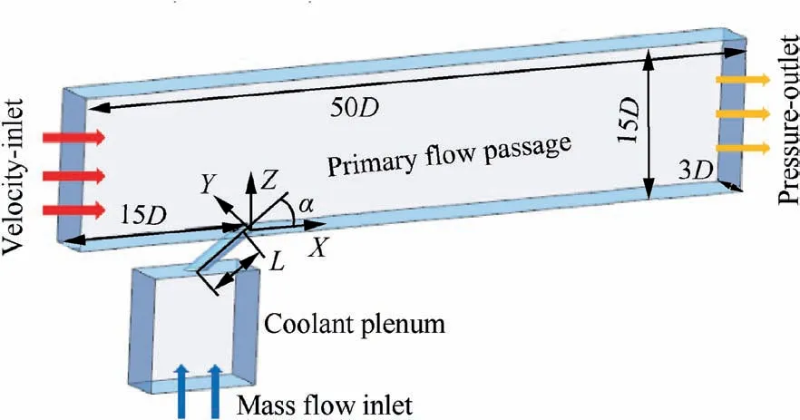
Fig. 1 Schematic diagram of computational domain.
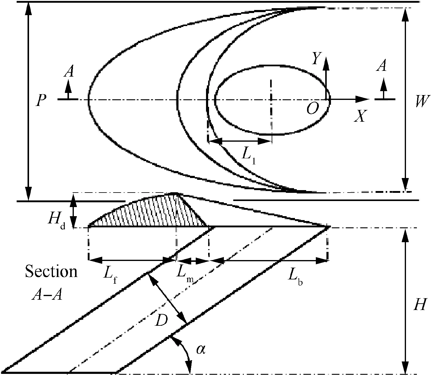
Fig. 2 Schematic diagram of SDR.

Table 1 Geometric parameters of SDR.
Totally, six kinds of film cooling structures are involved in current study, as described in Table 2.
In accordance with Fig. 1, the boundary conditions at primary flow inlet, coolant plume inlet, mixing flow outlet and film-cooled surface are summarized in Table 3.
Both the coolant and the primary flow are treated as idea gas.At the mainstream inlet, a fully developed velocity profile is specified to establish a boundary layer flow near the plate surface, according to the 1/7th power law, that is
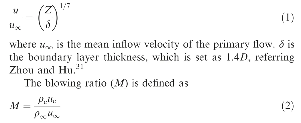
where uis the velocity of the cooling jet. ρand ρare the fluid densities corresponding to the coolant and the primary flow, respectively.
3. Computational method
Numerical simulations are conducted by solving the steady Reynolds-Averaged Navier-Stokes (RANS) equations with the use of commercial CFD software. The second order upwind scheme is used for spatial discretization of the convective terms. Convergence is regarded to be achieved when the reduction in all residuals is of five orders of magnitude.
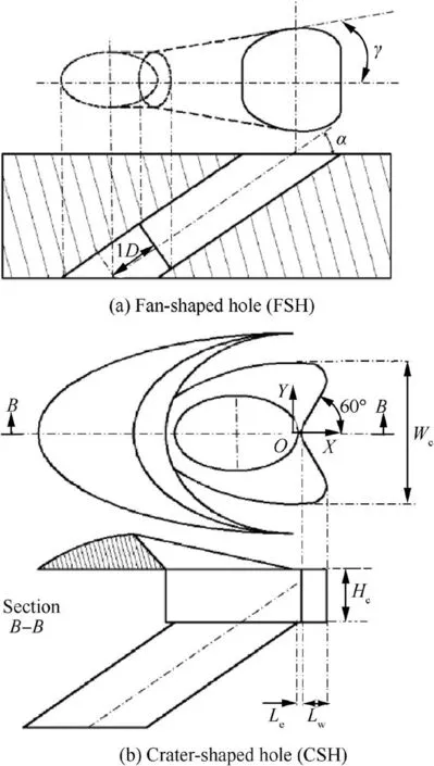
Fig. 3 Schematic diagram of two shaped holes.
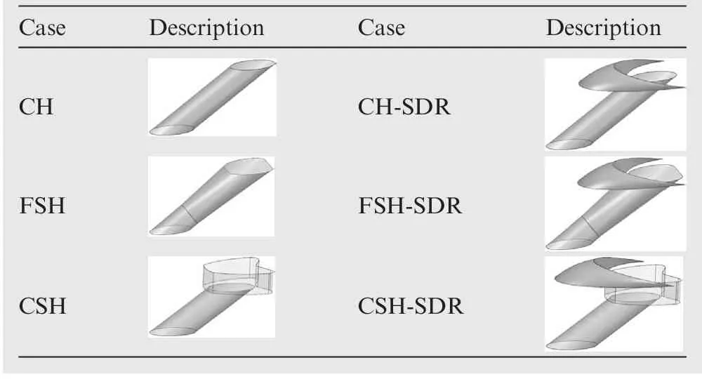
Table 2 Brief summary of film cooling structures.
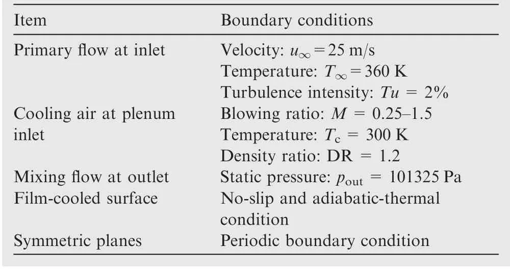
Table 3 Boundary conditions.
From the solved temperature distribution on the surface,the local adiabatic film cooling effectiveness(η)is deduced as

where Tis the recovery temperature of the mixed flow near the surface, namely, the adiabatic wall temperature.
By the line-average within one hole-to-hole pitch, the laterally-averaged adiabatic film cooling effectiveness (η)is obtained.
Generally,the structured grids are constructed for the computation of film cooling in the situations where the SDR is absent, as displayed in Fig. 4(a). In the situations where the SDR is presented, the mixed grid meshes are generated by using both the unstructured grids and the structured grids, as displayed in Fig. 4(b). The unstructured grid construction is applied in the vicinity of the sand-dune-shaped ramp to fit well with the SDR shape.While in the other regions,the structured grid construction is used.The meshes near the solid surface are refined to satisfy the viscous clustering requirement. In order to obtain reasonable computational meshes, a grid sensitivity test is conducted in advance. As illustrated in Fig. 4(c), the final grid number in the CH-SDR case is selected as 2.3 million approximately. In this situation, the maximum wall neighboring-cell Zis about 0.95, which matches well the requirement of enhanced wall treatment in the modeling of turbulence characteristics. Similarly, the grid independent solution is obtained in accordance with the other different film cooling structures, varying between 2.3-3.0 million grids.
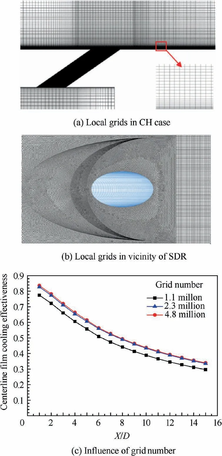
Fig. 4 Computational grids and sensitivity test.
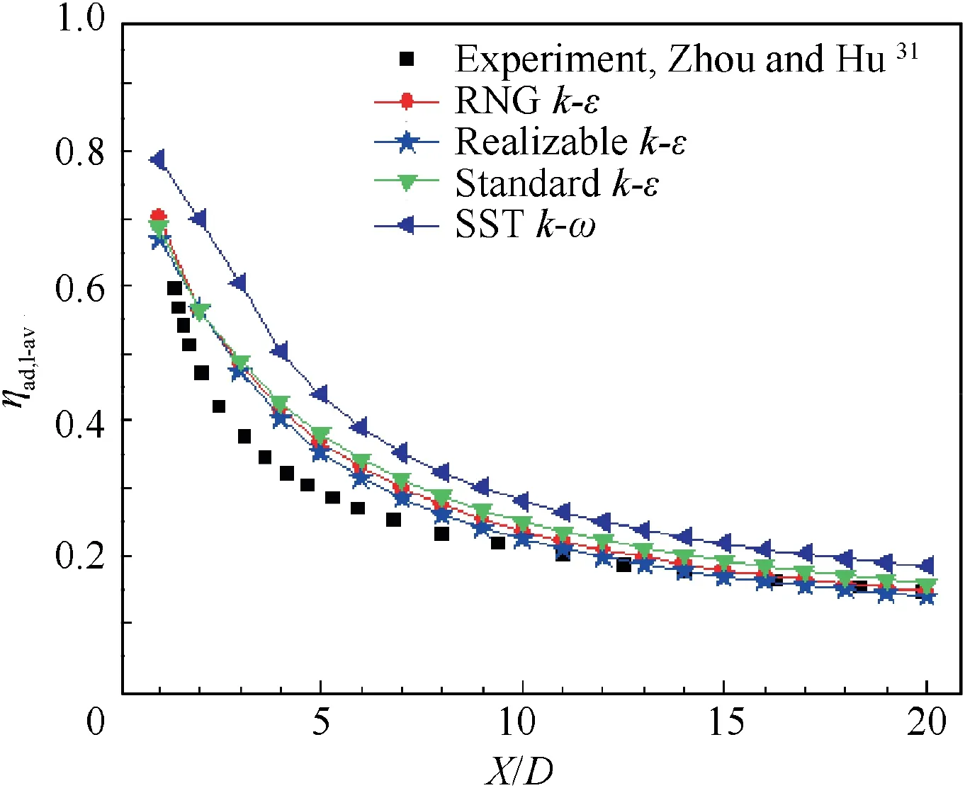
Fig. 5 Validation of computational scheme (M=0.4).
To assess an appropriate turbulence model, four typical two-equation turbulence models are selected for comparison in advance, against to experimental model of Zhou and Hu.Fig. 5 presents the computed ηat M=0.4, by using different two-equation turbulence models.It is seen that the realizable k-ε turbulence model provides a favorable prediction when compared to the other two-equation turbulence models. The maximum deviation is found to be less than 13% relative to the experimental data. Referring to previous works,consequently, the realizable k-ε turbulence model is adopted in the current study to model the turbulence characteristics.
4. Results and analysis
4.1. Flow fields of jet-in-crossflow
In the current section, the detailed flow fields of film cooling under M=0.75 are presented and analyzed.
Fig.6 shows the local streamlines distribution near the film hole, colored by the dimensionless temperature(Θ=(T-T)/(T-T)). Fig. 7 presents the dimensionless temperature contours and local streamlines distribution on a streamwise plane of X/D=1. It is confirmed that the Counter-rotating Vortex Pair (CVP) is a dominant feature in the near fields of film-cooling hole for the most cases, except for FSH-SDR case. However, the size and position of CVP are apparently changed by the use of shaped holes and upstream ramps, when compared to the baseline cylindrical hole. For FSH and CSH, the mean coolant injection velocity or momentum in FSH and CSH is effectively weakened, due to the diffused exit in the former case and the pre-diffusion of cooling air inside the shallow cavity in the latter case.Therefore, the penetration of CVP is effectively suppressed and the cores of CVP are pushed toward bi-lateral sides.In particular,for CSH case, an additional pair of anti-CVP is generated at the center of the contoured crater, as displayed in Fig. 6(c)and Fig. 7(c). As the V-shaped protrusion of crater forces the cooling air divert laterally, correspondingly, the rolling-up of cooling air at the branched protrusions is responsible for the formation of kidney vortices.On the other hand,the rolling-up of cooling air at the central wedge is responsible for the formation of anti-kidney vortices.
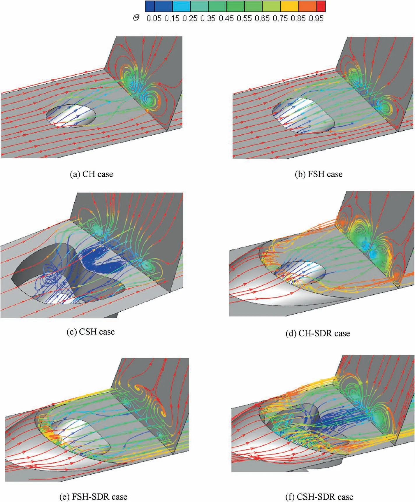
Fig. 6 Local streamlines distribution near film cooling hole.
In CH-SDR case, an additional anti-CVP pair is also observed outside the central CVP pair, as displayed in Fig. 6(d) and Fig. 7(d). This additional pair of anti-kidney vortices is resulted from the mixed flow shedding from the two tail horns of sand-dune-shaped ramp. Due to this additional anti-kidney pair of vortices, the size of CVP is effectively reduced. Concerning the fan-shaped hole in the presence of a SDR, as seen in Fig. 6(e) and Fig. 7(e), the classical CVP is rarely appeared, but replaced dominantly by a pair of anti-CVP.As known that the upstream ramp deflects the oncoming primary flow upwards to alleviate the jetting effect inside the film cooling hole,thus coolant flow inside the film cooling hole is modified to provide a broader coverage in the lateral direction immidiately downstream the film cooling hole. For this cause, the CVP is hardly formed and the mixed flow behind the SDR forms a CVP-like structure in which the rotational directions are opposite to the classical CVP pair. With redard to CSH-SDR case, as seen in Fig. 6(f) and Fig. 7(f),the cooling air is more spreading in the lateral direction when compared to CSH case due to the same cause. In particular,the cooling air at the central wedge is closer to the downward surface,thus the anti-CVP appeared in CSH case is not formed in CSH-SDR case.
Fig. 8 shows the dimensionless temperature contours and local streamlines distribution on a streamwise plane of X/D=8. It is seen that the far-field downstream of film cooling hole is generally dominated by the original vortical structures in the near filed, for the CH, FSH, CH-SDR, and FSH-SDR cases. While for CSH case, the anti-CVP appeared in the near field disappears, indicating that this anti-CVP is weaker than the CVP rolling-up at the branched protrusions. For CSHSDR case, when compared to the near field, although the far-field behind the film cooling hole is also found to be mainly dominated by the kidney-like vortices,the rotational directions are opposite to the original CVP pair. Seen from Fig.6(f), the cooling air is more concentrated at the central wedge.Although it hardly form an anti-CVP in the near field, the rolling-up of the cooling air at the central wedge happens downstream of film cooling hole,dominating the far-field flow.By comparison, the coolant coverage on the surface is also modified by the presence of an sand-dune-shaped ramp,regardless of film-hole shapes.
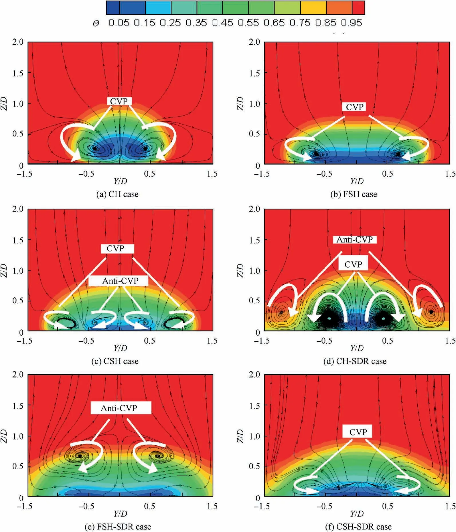
Fig. 7 Dimensionless temperature contours and streamlines on X/D=1 plane at M=0.75.
Fig. 9 and Fig. 10 present the dimensionless temperature contours and local streamlines on the film-hole centerline plane and the horizontal plane immediately above the film-cooled surface (Z/D=0.125), respectively. With respect to the baseline CH case,the cooling jet penetration into the primary flow is effectively suppressed by the use of shaped holes,as displayed in Fig. 9(b) and Fig. 9(c). Simultaneously, the lateral flow of coolant jet is enhanced by the use of shaped holes,as displayed in Fig.10(b)and Fig.10(c).With regard to CH-SDR,the nearwall flow of the oncoming primary flow is deflected upward before it interacts with the coolant jet. Behind the upstream ramp a weaker flow separation occurs,so that the direct impact of the primary flow onto the coolant jet injection is consequently weakened. For this cause, the coolant injection at the front zone of film-hole exit is modified, leading to a more uniform outflow as well as a stronger lateral flow of coolant injection, as displayed in Fig. 9(d) and Fig. 10(d). The effect of upstream ramp on the mutual interaction between shapedhole coolant jet and primary flow also behaves, as demonstrated in Fig.9(e)and Fig.9(f).For instance,when compared with Fig.9(c),the pre-diffusion of cooling air in CSH-SDR case(as seen in Fig.9(f))occupies more space in the concave cavity.This implies that the ‘‘jetting effect”of coolant flow inside the film cooling hole is alleviated and more uniform coolant outflow is formed subsequently. Furthermore, the lateral spreading of coolant jet from shaped hole is further aggravated by the integrity of an upstream ramp, which leads to a more uniform temperature distribution over the film-cooled surface, as displayed in Fig.10(e) and Fig. 10(f).
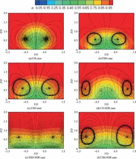
Fig. 8 Dimensionless temperature contours and streamlines on X/D=8 plane at M=0.75.
4.2. Adiabatic film cooling effectiveness
In accordance with the above flow features, the combined effects of shaped holes and upstream ramp on the local film cooling effectiveness are reflected in Fig. 11 and Fig. 12.
Under M=0.5,the coolant jet shows a better coverage on the film-cooled surface in the vicinity of film-hole centerline,even for CH case. Due to the effective cancellation of the kidney vortex, both FSH and CSH lead to a wider lateralcoverage of the coolant jet in contrast to CH case. With the presence of upstream ramp, the local adiabatic film cooling effectiveness in the zone between adjacent holes is significantly improved in relative to the corresponding case without an upstream ramp. However, as the enhancement of coolant lateral spreading otherwise weakens the streamwise spreading of coolant jet, under a small blowing ratio, the local adiabatic film cooling effectiveness far downstream at the film-hole centerline is relatively reduced in the presence of upstream ramp.
Under M=1.0, the use of a shaped hole or an upstream ramp is more pronounced on enhancing the film cooling effectiveness.Of particular,under a higher blowing ratio, the combined effect of shaped hole and upstream ramp on film cooling enhancement behaves more fully over nearly entire film-cooled surface. In the presence of SDR, the coolant lateral spreading is enhanced, leading to a wider coolant coverage. At the same time, the influence of strong lateral flow on the streamwise spreading of coolant jet is well balanced by its active role on the suppression of coolant jet normal penetration.
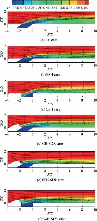
Fig. 9 Local streamlines and dimensionless temperature contours on hole center plane at M=0.75.
4.3. Averaged adiabatic film cooling effectiveness
Fig. 13 presents a direct comparison of the laterally-averaged adiabatic film cooling effectiveness (η) along streamwise direction. Under M=0.25, although the shaped hole and the upstream ramp show active roles on improving the film cooling effectiveness with respect to the baseline CH case,the combined effect of the shaped hole and upstream ramp dose not appear in comparison with the respective role of shaped hole or upstream ramp, as displayed in Fig. 13(a).Under M=0.5, the benefit of the use of shaped holes or upstream ramp on improving the film cooling effectiveness begins to appear obviously, as displayed in Fig. 13(b). In this situation, CH-SDR produces a more pronounced improvement on the film cooling effectiveness than FSH or CHS. By using the combination of shaped holes and upstream ramp,the ηcould be increased about 30% when compared to their individual role. With the blowing ratio increases, the combined effect of shaped holes and upstream ramp behaves more pronouncedly.Under M=1.0,it is found that the active role of shaped holes takes advantage over CH-SDR case, as seen in Fig. 13(c). FSH-SDR case is identified to be superior to CSH-SDR case.Its superiority is more demonstrated under M=1.5, as seen in Fig. 13(d).
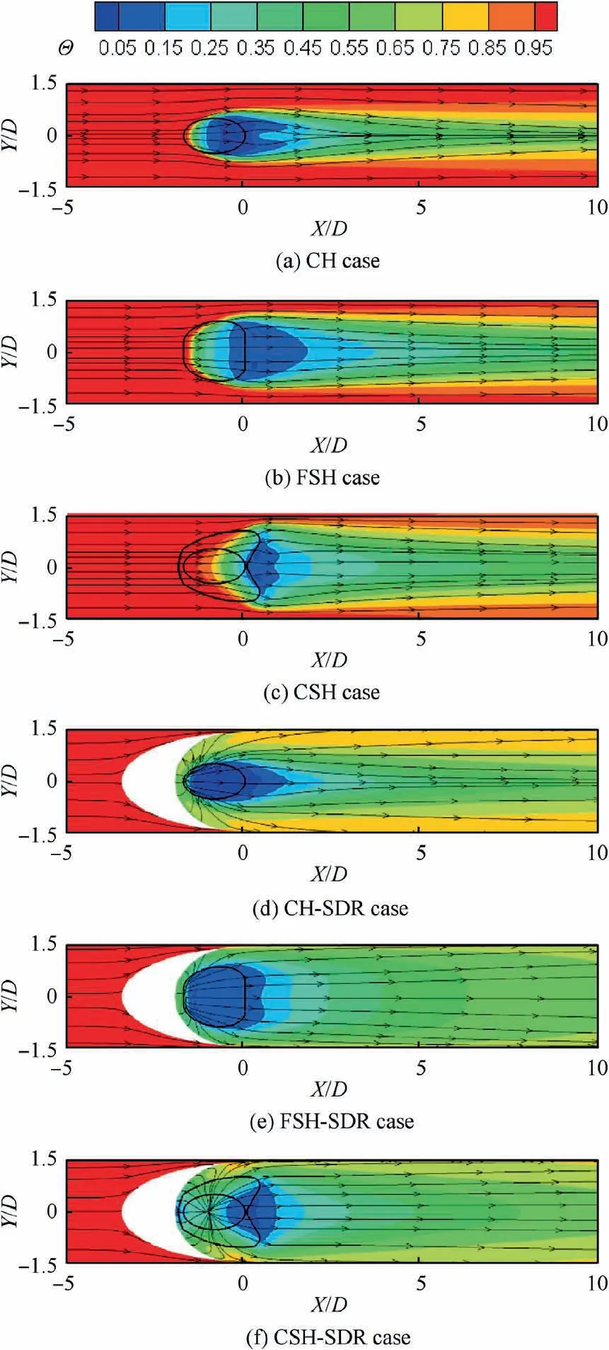
Fig.10 Dimensionless temperature contours and streamlines on a horizontal plane of Z/D=0.125 at M=0.75.
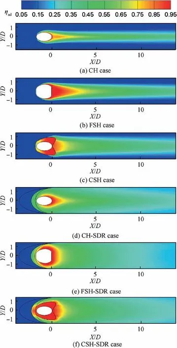
Fig. 11 Local adiabatic film cooling effectiveness distributions under M=0.5.
Evaluated in terms of the spatially-averaged adiabatic film cooling effectiveness (η) in a specific zone between X/D=0 and X/D=15, as seen in Fig. 14, only about 20%increase is achieved by using shaped holes or upstream ramp under M=0.25, when compared to the baseline CH case.Under M=0.5, about 50% increase of ηis produced in FSH and CSH cases.By using the combination of shaped holes and upstream ramp,this achievement could reach up to 100%.When the blowing ratio is beyond 1.0, the advantage of the combined effects of shaped holes and upstream ramp on improving film cooling effectiveness behaves more significantly,especially for FSH-SDR scheme.Interestingly,the most appropriate blowing ratio for achieving the biggest ηis altered for different cooling configurations. The appropriate blowing ratio is 0.5 for CH case. This value is 0.75 for CH-SDR case and 1.0 for FSH, CSH and CSH-SDR cases. With regard to FSH-SDR case, ηis increased monotonously with the increase of blowing ratio, among the current bowing ratio range. It is suggested that FSH-SDR is a most favorable film cooling scheme, especially under higher blowing ratios.
4.4. Preliminary assessment on effect of density ratio
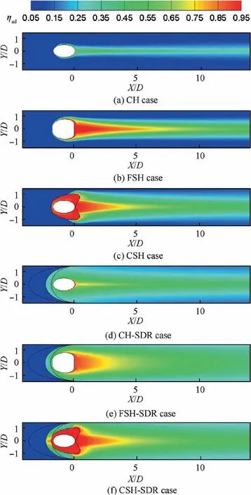
Fig. 12 Local adiabatic film cooling effectiveness distributions under M=1.0.
In the engine representative condition, the coolant-tomainstream Density Ratio (DR) is generally around 2.According to previous researches,the coolant-tomainstream density ratio has a certain influence on the film cooling effectiveness. To clarify the effect of DR on the film cooling in the presence an upstream SDR, a preliminary numerical-assessment is conducted for CH-SDR case. The density ratio is specified as 2.0 by altering the coolant temperature. Fig. 15 compares directly the laterally-averaged film cooling effectiveness between DR=1.2 and DR=2.0,under three typical blowing ratios. It is seen that the film cooling effectiveness is increased a little immediately downstream of film cooling hole at a large density ratio, under M=0.5.While under higher blowing ratios, the laterally-averaged film cooling effectiveness at DR=2.0 is obviously increased when compared to that at DR=1.2. These results are in good agreement with the previous findings where no upstream ramps are presented,confirming that the effect of DR on film cooling effectiveness still remains in the SDR case.
Furthermore, the aero-thermal performances and the layout of SDR in the real applications of thermal protection design on hot-sectional components need comprehensive concerns.To our knowledge,these specific film-cooling configurations would be more appropriately used at the endwalls of turbine blade. In such a situation, the effect of the nonuniform inlet flow condition is a quite important factor that affects the film cooling performances,remains illustrated.
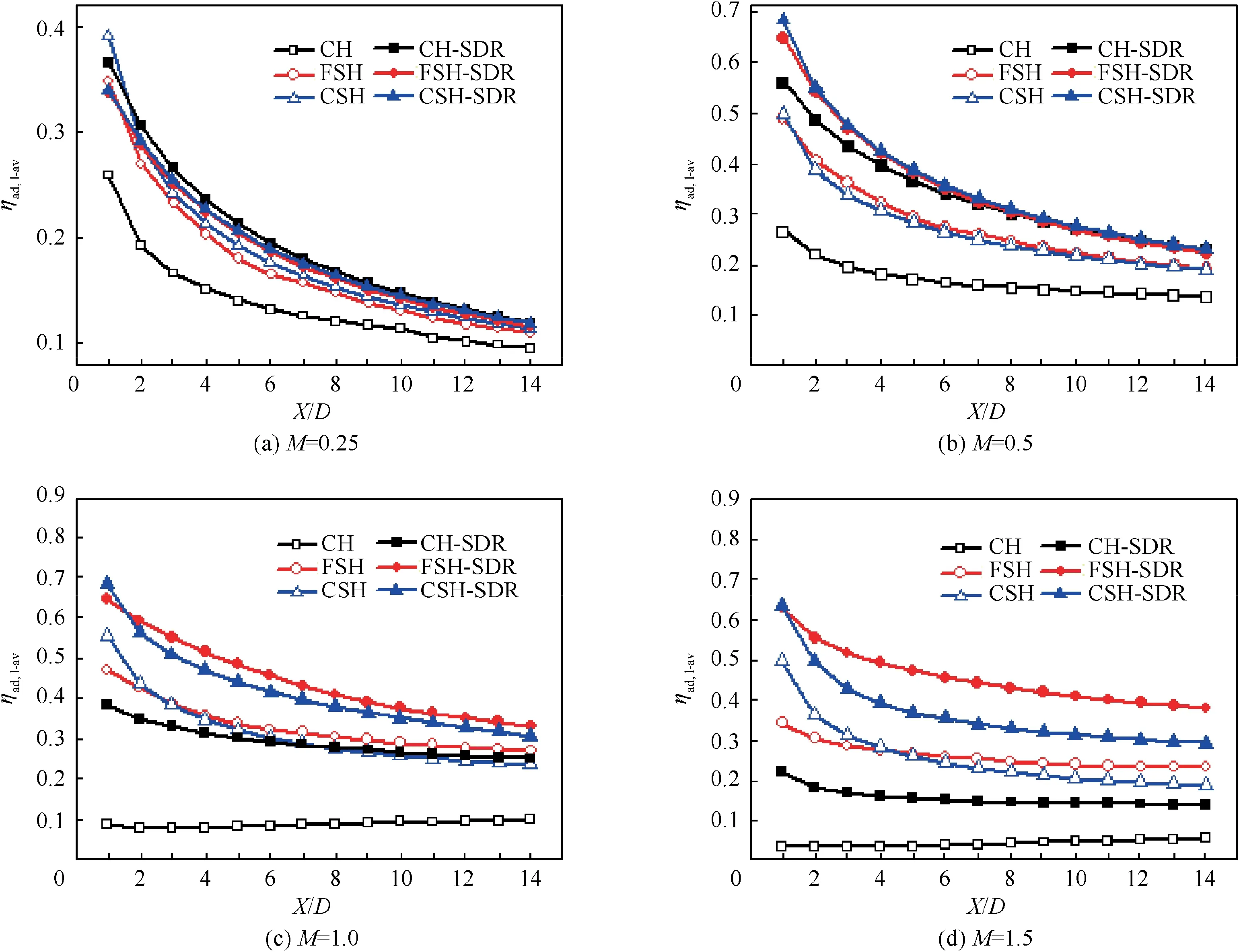
Fig. 13 Laterally-averaged adiabatic film cooling effectiveness.
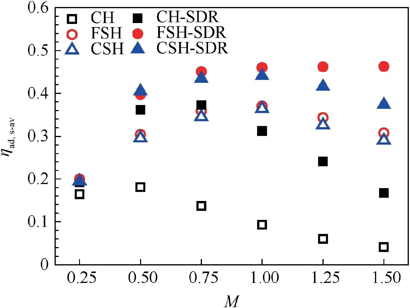
Fig.14 Spatially-averaged adiabatic film cooling effectiveness in a specific zone (0 ≤X/D ≤15).
5. Experimental validation
For validation purpose,an experimental test performed in current study.The test setup is schematically shown in Fig.16(a).The primary flow passage has a cross-section dimension of 40D (streamwise length)×27D (spanwise width). Seven holes are involved in a single-row film cooling, arranged with a uniform hole-to-hole pitch of 3D, as seen in Fig. 16(b). Both the geometric parameters of film cooling holes and the geometric of the upstream ramps are designed as the same as that in the numerical simulations. The test piece is made of polymethyl methacrylate,which has a thickness of 2.25D and small thermal conductivity of 0.2 W/(m·K) approximately. The length-to-diameter of hole (L/D) is 3.92.
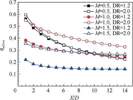
Fig. 15 Effect of DR on laterally-averaged film cooling effectiveness for CH-SDR.
During the experimental tests,the inlet velocity and temperature of the primary flow are regulated to be 25 m/s and 360 K respectively, which provides a coolant-to-mainstream Density Ratio(DR)of 1.2.The temperature of the coolant flow is about 300 K. Three blowing ratios (M=0.5, 1.0 and 1.5) are adopted.The mass flow-rates of both flows are measured by calibrated flow meters.The inlet temperatures of primary flow and the injection temperature of coolant jet are measured by K-type thermocouples. The temperature on the film-cooled surface is measured by an infrared camera, through an infrared glass mounted on the primary flow channel opposite to the filmcooled surface. To ensure a nearly perfect emissivity of unity,the film-cooled surface is coated by a uniform thin black paint.
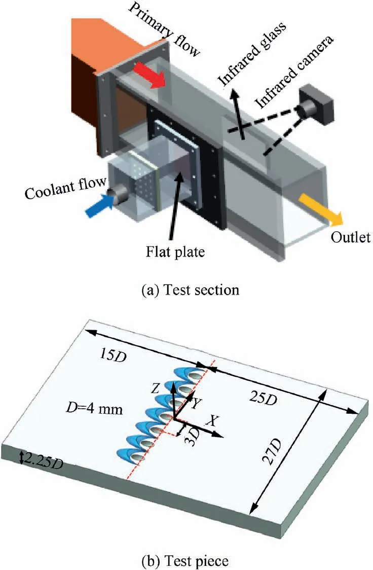
Fig. 16 Schematic diagram of experiment setup.
As the test piece is not perfectly thermal adiabatic,the measured temperature on the plate surface is not exactly the adiabatic wall temperature. The film cooling effectiveness directly calculated from the measured temperature is a ‘‘measured”value, that is

where Tis the measured wall temperature.
From the temperature calibration,the precision uncertainty of the thermocouples is about ±0.5°C. Considering a bias uncertainty of IR camera specification, the total uncertainty of wall temperature (T) is selected as ±1.5%. Hence, the maximum uncertainty in the ‘‘measured” film cooling effectiveness is estimated to be ±5.5%, according to the theory of error transfer.
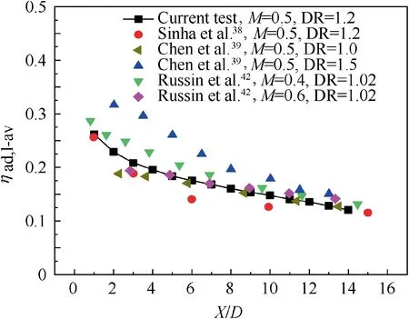
Fig. 17 Comparisons of laterally-averaged film cooling effectiveness for CH.
An indirect correction is made to obtain the adiabatic film cooling effectiveness,by using the one-dimensional conduction correction method.


Table 4 Geometric parameters in relevant researches.
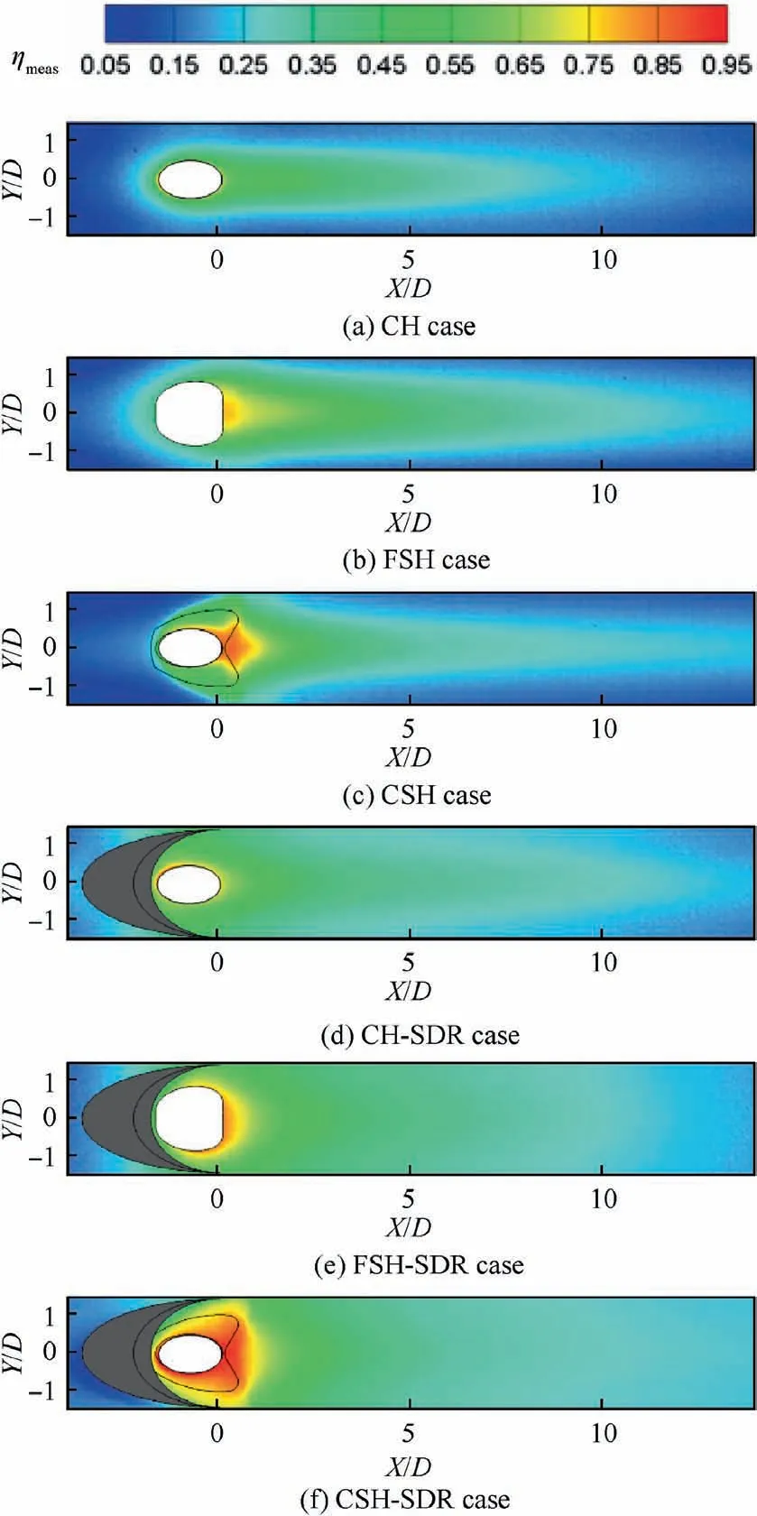
Fig. 18 Local measured film cooling effectiveness distributions under M=0.5.
where ηis the correction factor in adiabatic effectiveness,which is selected as 0.06 in the current experiment, referring Ethridge et al.
A direct comparison of the laterally-averaged adiabatic film cooling effectiveness distributions for CH case between current study and previous relevant researchesis presented in Fig. 17. Among them, three techniques are used to derive the film cooling effectiveness,including the Infrared(IR)thermography, Thermocouple (TC) measurement, and Pressure Sensitive Paint (PSP) method. The main geometric parameters in these researches are listed in Table 4. Generally, the presented result is in good agreement with that presented by Sinha et al.,both film cooling configurations have nearly the same geometric parameters. Referring Chen et al.,the present result is obviously less than that at DR=1.5 but agrees well with that at DR=1.0.Seen from Table 4,The cylindrical hole adopted by Chen et al.has a smaller inclination angle and a bigger length-to-diameter ratio. These factors (such as bigger length-to-diameter ratio, smaller inclination angle and larger density ratio) are all attributed to produce higher film cooling effectiveness. In addition, it is also seen that the present result agrees qualitatively with that presented by Russin et al.
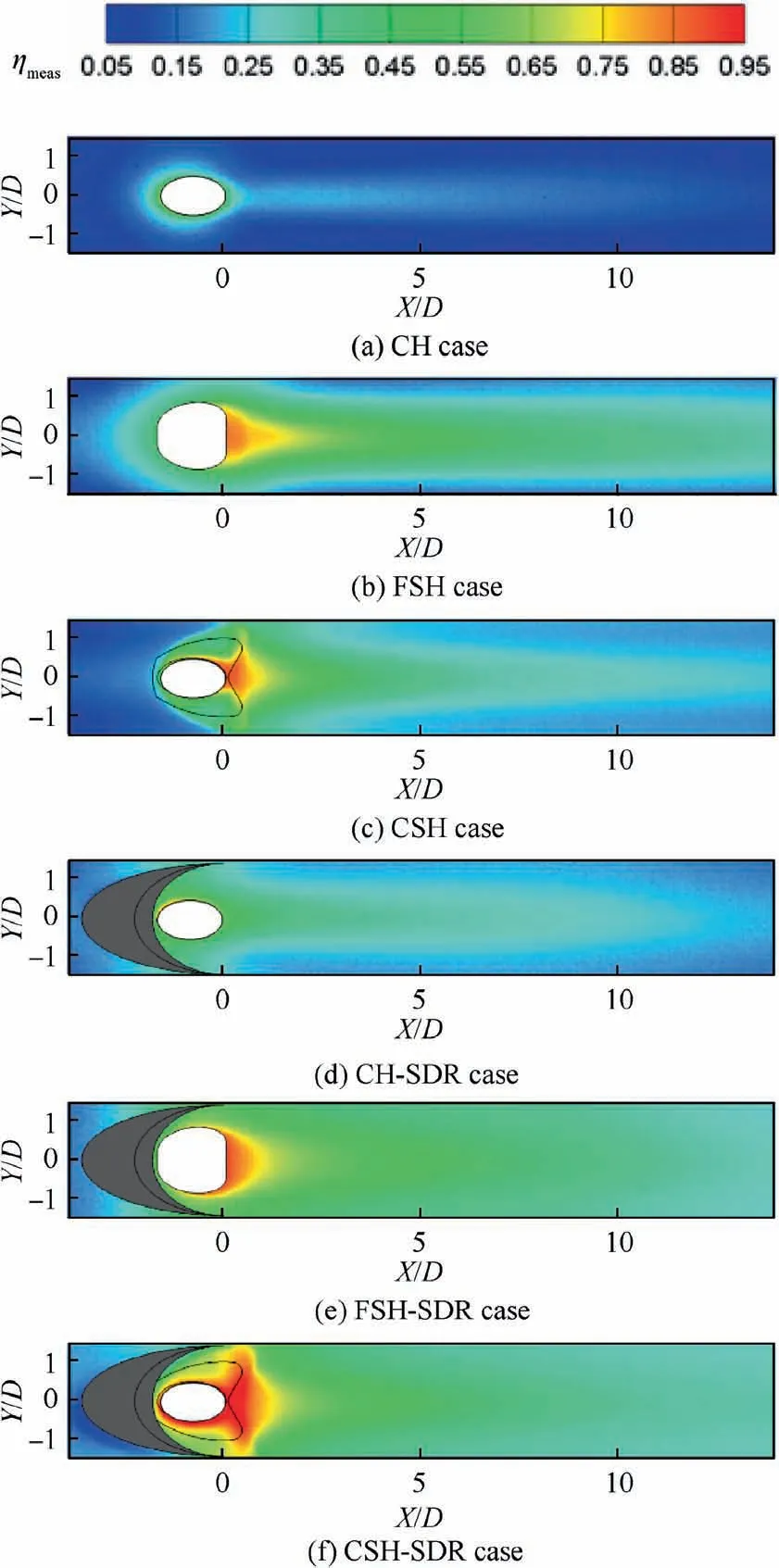
Fig. 19 Local measured film cooling effectiveness distributions under M=1.0.
Fig.18 and Fig.19 present the local‘‘measured”film cooling effectiveness distributions, under M=0.5 and M=1.0,respectively. Comparing them with Fig. 11 and Fig. 12, it is confirmed that the effects of the shaped hole and upstream ramp on film cooling effectiveness captured from experimental tests are similar to that found in numerical simulations. It is also found that there are certain differences between the‘‘‘measured” local film cooling effectiveness distributions and the ‘‘computed” film cooling effectiveness distributions. As mentioned above,although the thermal conductivity of the test piece is small, the heat conduction effect inside the solid wall could not be completely eliminated.For this reason,the‘‘measured” temperature distribution tends to be homogenized.Immediately downstream of the hole exit, the local ‘‘measured” film cooling effectiveness is reduced in the holecenterline region,but its distribution along the spanwise direction is more uniform with respect to the‘‘computed”adiabatic film cooling effectiveness distribution.
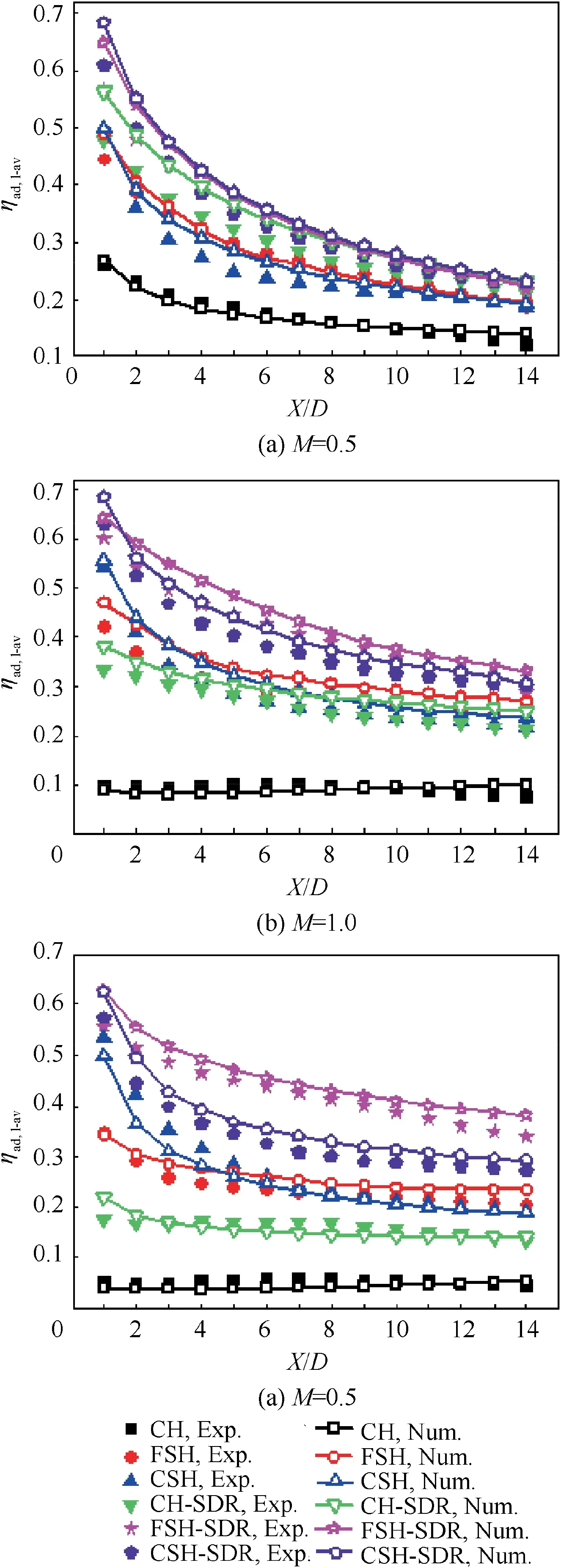
Fig. 20 Comparison of measured and computed ηad,l-av.
Fig. 20 presents a direct comparison of the measured and computed laterally-averaged adiabatic film cooling effectiveness distributions for the involved cases.It is sure that the numerical simulation is generally over-predicts the film cooling effectiveness for most cases.The maximum deviation is about 15%.
6. Conclusions
From current study, the following conclusions are deduced
(1) The SDR shows an inherent affecting mechanism on the mutual interaction of jet-in-crossflow.In CH-SDR case,an additional pair of anti-kidney vortices could be resulted from the mixed flow shedding from two ramp horns. For FSH-SDR and CSH-SDR cases, the kidney-like vortices dominating the far-field downstream of film cooling hole take opposite rotational directions with respect to their original cases without the presence of upstream ramp.
(2) The SDR aggravates the lateral spreading of cooling jet and thus improves the film cooling uniformity significantly. The laterally-averaged film cooling effectiveness is confirmed to be increased with the use of SDR,regardless of film-hole shape and blowing ratio. Under higher blowing ratios, the role of SDR on film cooling enhancement behaves over nearly the entire zone.However, under small blowing ratios, the local film cooling effectiveness at far-downstream film-hole centerline is relatively reduced otherwise.
(3) Evaluated in terms of the spatially-averaged film cooling effectiveness in a specific zone between X/D=0 and X/D=15,only about 20%increase is achieved by using shaped holes or upstream ramp under M=0.25 with respect to the baseline CH case. Under M=0.5, about 50% increase is produced by FSH and CSH. By using the combination of shaped holes and SDR,this achievement could reach up to 100%. This combined effect behaves more significantly when the blowing ratio is beyond 1.0. It is suggested that FSH-SDR is a most favorable film cooling scheme.
(4) The most appropriate blowing ratio for achieving the biggest spatially-averaged film cooling effectiveness is associated with the film cooling configurations. For CH case,the appropriate blowing ratio is 0.5.This value is 0.75 for CH-SDR case and 1.0 for FSH, CSH and CSH-SDR cases. With regard to FSH-SDR case, the spatially-averaged film cooling effectiveness is increased monotonously with the increase of blowing ratio,among the present bowing ratio range.
Declaration of Competing Interest
The authors declare that they have no known competing financial interests or personal relationships that could have appeared to influence the work reported in this paper.
Acknowledgments
The authors gratefully acknowledge the financial support for this project from the National Natural Science Foundation of China (No. U1508212) and National Science and Technology Major Projects (Nos. 2017-III-0011-0025 and 2017-III-0011-0037).
 CHINESE JOURNAL OF AERONAUTICS2021年4期
- CHINESE JOURNAL OF AERONAUTICS的其它文章
- Time delay compensation in lateral-directional flight control systems at high angles of attack
- Dual stability enhancement mechanisms of axial-slot casing treatment in a high-speed mixed-flow compressor with various tip clearances
- Development cost prediction of general aviation aircraft using combined estimation technique
- Modeling and parameter identification of linear time-varying systems based on adaptive chirplet transform under random excitation
- An experimental method to obtain the hard alpha anomaly distribution for titanium alloy aeroengine disks
- Vibration analysis and control technologies of hydraulic pipeline system in aircraft: A review
