Dual stability enhancement mechanisms of axial-slot casing treatment in a high-speed mixed-flow compressor with various tip clearances
Qianfeng ZHANG, Juan DU,*, Jihao LI, Ming ZHAO,Hongwu ZHANG
a Institute of Engineering Thermophysics, Chinese Academy of Sciences, Beijing 100190, China
b University of Chinese Academy of Sciences, Beijing 100190, China
c Department of Mechanics, School of Mechanical Engineering, Tianjin University, Tianjin 300072, China
KEYWORDS Aerodynamic stability;Casing treatment;Compressor;Numerical simulation;Stability enhancement
Abstract The influence of Axial-Slot Casing Treatment (ASCT) on the performance and stability enhancement mechanisms of ASCT were experimentally and numerically investigated in a highspeed mixed-flow compressor under three different tip clearances. Unsteady simulations showed the compressor stalled through end-wall stall route, i.e. the spike stall inception originating from rotor tip region, which was validated by dynamical measurements. When the ASCT was applied,greater than 20%of Stall Margin Improvement(SMI)could be achieved for the compressor under each tip clearance size. The streamwise velocity contours and flow structures in the tip region and axial slots were deeply analyzed to explore how the so called ‘‘suction and injection effects”generated by the ASCT manipulate tip clearance flow and enhance the stability of compressor under different tip clearances. It was found that the dominant stability enhancement mechanisms of ASCT varies with tip clearance size for the mixed-flow compressor. (A) For the small tip clearance, the dominant mechanism of stability enhancement is the blockage reduction generated in the blade passage by the suction effect of ASCT.(B)For the large tip clearance,the injection effect of the ASCT is the dominant mechanism of stability enhancement with ASCT, which plays the leading role in delaying the spillage of incoming/tip leakage flow interface at the rotor Leading Edge (LE) plane.
1. Introduction
Compressor constitutes up to 50% of the weight of a modern aero-engine.Reducing the number of stages can decrease compressor weight but increase the stage pressure ratio and loading. Higher pressure ratio and loading may induce strong tip leakage flow and serious flow separation on the Suction Side (SS), resulting in reducing the Stall Margin (SM) of a compressor. Hence, it is a challenge for engineers to design highly-loaded compressors with wide SM for aircraft jet engines. Additionally, in such conditions as inlet swirl distortion, the SM definitely decreases, which imperils aircrafts safety.
A compressor with small SM requires additional approaches to acquire large operation range. An effective method of enhancing the stability of a compressor is Casing Treatment (CT), which has been extensively investigated and even been applied in real engines because of its effectiveness.There are several types of casing treatment, such as the groove-type,slot-type,stall precursor-suppressedand self-recirculation Tip Blowing Casing Treatment (TBCT).The slots-type CT has drawn more attention for its more outstanding capability of extending the SMthan that achieved by circumferential groove type and TBCT. The SM extension brought by the circumferential groove type and TBCT is approximately 5%-15%,while the slot-type CT can extend the SM by as high as 20%-40%.Tests on a variety of CT configurationshad verified that using the slot-type CT could substantially extend SM when a certain loss in efficiency was allowed at the design point. However, Streit et al.showed that an advanced semi-hearted ASCT mounted on a transonic compressor could significantly extend the SM without adverse effect on the efficiency.
Actually,tip clearance size can be altered by stress-induced deformation and thermal expansion of blades during compressors operation. Most modern compressors are designed to be tip-critical,which means that stall cells are initiated in the tip region owing to tip leakage flow and boundary layer. Tip leakage flow is driven by the pressure difference between rotor Pressure Side (PS) and SS through tip clearance, which allows for free relative motion between rotor and casing. Therefore,tip clearance size is very important to a compressor. Typically the relative size of tip clearance is small in the front stages,and becomes large in the rear stages of aero engines or gas turbines owing to small blade heights or chords. Tip clearance size is a key parameter influencing compressor efficiency and stability,as it has been experimentally and numerically investigated in low-speed compressors or high-speed compressors by numerous researchers in the past 40 years.All the results showed that efficiency and SM decreased with increasing tip clearance.Therefore, it is necessary to study the effect of tip clearance size on compressor performances and on stability enhancement mechanisms of ASCT.
Generally,the effects of ASCT on compressor stability and efficiency highly depend on the key geometrical parameters including the location,open-area-ratio, height, width and skewed angle of slots, as well as the compressor tip clearance size. A large amount of works aiming to understand the influence mechanisms of ASCT on compressor aerodynamic performances have been reported.Up to now, it has been well accepted that the stability enhancement mechanisms of ASCT are to energize incoming flow and reduce blockage.However, very few have studied the effect of tip clearance size on the performance of a compressor with ASCT. Limited by CFD techniques, Moore and Osbornexperimentally investigated the influences of tip clearance(0.48%,0.81%,1.1%and 1.4%span)on the overall performance of a transonic fan stage with and without CT. For the smallest tip clearance, he found that the efficiency of the compressor with skewed slot casing treatment was lower than that of the compressor with solid casing,and the decrease of efficiency with increasing clearance was not as rapid.Cevik et al.studied a sawtooth-shaped circumferential groove to reduce compressor performance and SM sensitivities to tip clearance increase (0.47%, 0.94% and 1.41% of tip chord). The numerical results showed that the CT provided a significant reduction in double leakage and that the reduction of double leakage increased with tip clearance size. Hence, CT reduced the sensitivity of performance and SM to tip clearance. Rolfes et al.experimentally studied the effect of circumferential groove CT in a three stage environment low speed axial compressor at two tip clearance sizes(1.2% and 5% of tip chord). At the small tip clearance, the grooves were almost neutral, only small reductions in total pressure ratio and efficiency compared to solid wall could be observed;while at the large tip clearance,it notably benefitted from the CT.
Summarizing the previous results, we can conclude: (A)Most works concentrated on the stability enhancement mechanism of CT at a constant tip clearance in compressors,less in compressors with various tip clearances; (B) Studies focused on effects of ASCT on compressor performances and stability enhancement mechanisms in axial compressors with relatively large tip clearance sizes. And there were no published papers containing analyses on mixed-flow compressors. Moreover,tip clearance can affect the dominant mechanisms of high incidence angle that triggers spike-type rotating stall,which elicits that the dominant mechanisms of enhancing stability by ASCT for compressors with different tip clearances may be various. With this question, the effects of a semi-circle ASCT on mixed-flow compressor performance were studied through simulations under three tip clearances.
This paper is organized as follows. A brief introduction about compressor model, numerical setup and the numerical validation are presented firstly. The stall mechanisms of the compressor under various tip clearances are discussed based on the numerical and experimental results. Then the performances of the studied compressor with and without ASCT under three tip clearances are introduced in detail. The underlying mechanisms of extending the stall margin with the aid of analyzing 3D flow structures, aerodynamic parameter and axial leakage velocity are presented in the following.The main conclusions are summarized at last.
2. Compressor model and research method
2.1. Compressor model
The test compressor is a highly-loaded one-stage mixed-flow compressor. It is part of an electrically powered active highlift system for future civil aircrafts. By utilizing a boundary layer suction slot on the suction side of the airfoil as intake for the compressor, the efficiency of the active high-lift system can be improved significantly. The sucked air is blown over a Coanda-surface at the flap. Its design and optimization processes were proposed by Teichel et al.The design parameters of the compressor are listed in Table 1.The design speed of the compressor is 60125 r/min. The design tip clearance size is 0.2 mm, corresponding to 0.32% rotor tip chord length (C).The compressor has a very small stall margin at the rotational speed of 30000 r/min,which is 50%of the design speed.There-fore,the experimental and numerical results presented here are obtained at this rotational speed. The ASCT investigated in this paper was designed by Du and Seumeusing the DOE(Design of Experiment) method. Finally, the most efficiencyfriendly case with enough stability improvement was chosen.The geometrical parameters depicting the slots are shown in Fig. 1 and the cross-section of the slots is a semi-circle. The applied ASCT consists of four semi-circle axial slots per blade passage,skewing with an angle(θ)of 60°inclined in the direction of rotor rotation. The length (L) and height (H) of the slots are 50%and 30%rotor axial tip chord length. The open area ratio calculated by slots width (w) and pitch length (p) is 0.2. Half of the slots overlaps with rotor, and the other half lays upstream of rotor LE. In Fig. 1, U and ω mean linear velocity and rational speed of the rotor, respectively.
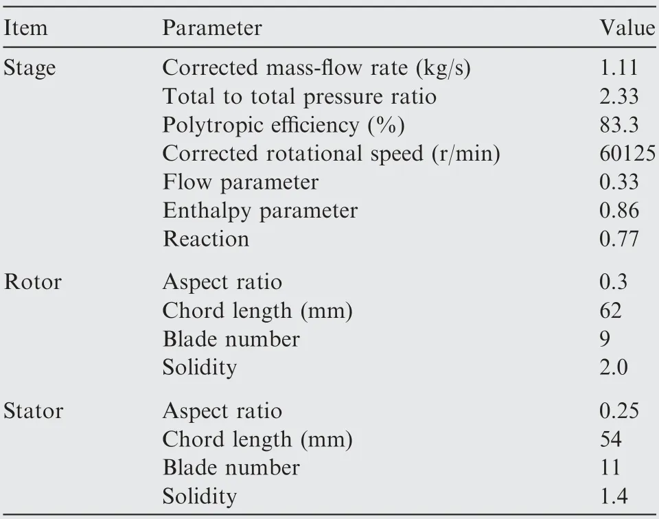
Table 1 Design point parameters of compressor.33
2.2. CFD set up
In this paper, unsteady simulations have been carried out at the Near Stall (NS) points to predict the operating range with and without the ASCT. A commercial solver, Ansys/CFX has been chosen to solve the unsteady Reynolds-Average Navier-Stokes(RANS)equations.The k-ω turbulence model with second order scheme was used after it has been confirmed that the turbulence model can well predict the operating range agreeing with the experimental data.To save the calculation time required by solving unsteady RANS equations, the singlepassage model was used to conduct numerical simulations.
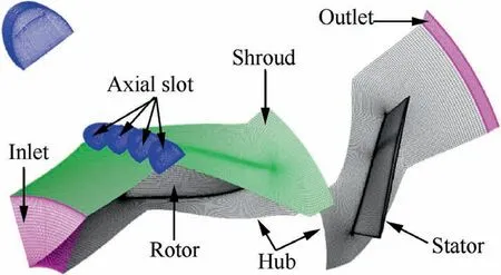
Fig. 2 Computational grids for stage and casing treatment.
The computation grid was determined after grid independence study in Ref.. Fig. 2 shows the single passage mesh.The rotor grids consist of 1.1 million nodes,the stator passage has 0.65 million nodes, and the casing treatment grids consist of 0.34 million nodes. Within the tip clearance in the radial direction,17 nodes were distributed.The scale of the first layer of grids next to the solid wall was set to 3×10m to ensure that yat most solid walls is less than 2.Unsteady simulations were performed employing 100 time steps per rotor blade period with a physical timestep of 2.22×10, and 10 inner iterations were set each time to obtain each converged solution.The convergence criterion of RMS(Root Mean Square)residual was set to 1×10.The inlet and outlet mass flow rate and a numerical probe located downstream of the rotor were monitored until the computation failed to converge.
To provide an appropriate inlet boundary condition for the single-passage computational model, we conducted the fullannulus simulation for the mixed-flow compressor. The full annulus computational model with inlet and outlet ducts is indicated in Fig. 3, which is the same as the test rig model.The characters ‘‘Inlet_exp” and ‘‘Outlet_exp” indicate the locations of collecting experimental data to calculate the static pressure ratio of the compressor. The total pressure distributions at ‘‘Inlet_single” of the full-annulus computation model were extracted as the inlet boundary condition of the singlepassage model. Hence, the total pressure loss generated in the inlet duct and the boundary layer near the end-wall were taken into account in the single-passage simulations. The exit boundary condition was given by average static pressure.Smooth non-slip and adiabatic conditions were defined on all solid walls. The axial slots were modeled in the stationary frame on a thin patch,which was connected to the rotor casing acting as a frozen rotor interface in the steady-state simulations.
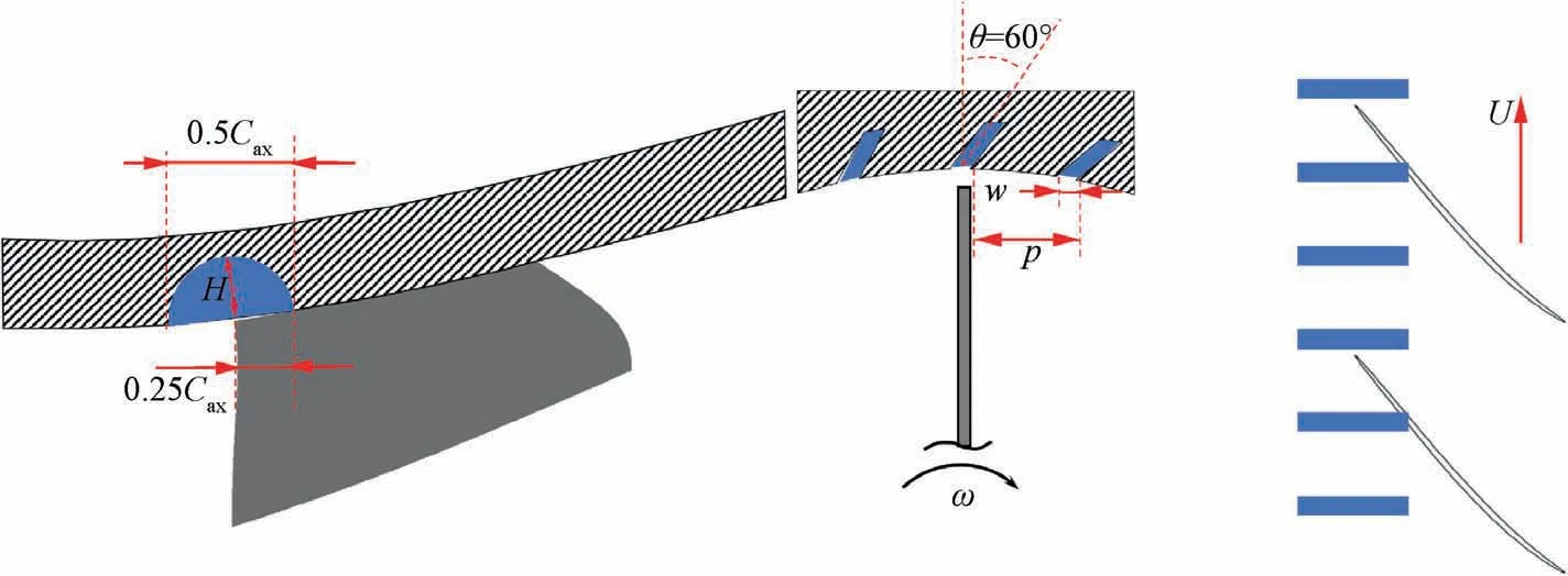
Fig. 1 Sketch of axial slot geometry.
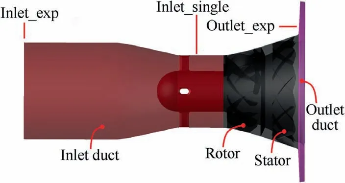
Fig. 3 Schematic map of compressor test rig with inlet and outlet ducts.
2.3. Experimental set up
Numerical validation has been done on the studied mixed-flow compressor with the Smooth Casing (SC). The measurements were carried out in Leibniz University Hannover. A crosssection of the compressor is presented in Fig. 4, including the positions of measurements upstream 1 and downstream 2 of the stage.At Position 1,three static pressure taps connected to a NetScanner 9116 (100 kPa) and three total temperature probes with PT100 thermometers were utilized. Moreover,the inlet stagnation pressure was measured with a Prandtl tube connected to a NetScanner 9816 (300 kPa). The stage outlet flow conditions at Position 2 were measured using six type K thermocouple probes and six static pressure taps connected to a NetScanner 9816 (300 kPa). All pressures were measured relative to the ambient pressure, which was monitored with a Mensor CPT6100. An ultrasonic gas flow meter was used at the inlet to measure the air mass flow. These variables were recorded with a sampling rate of 5 Hz.
A series of high frequency response Kulite pressure transducers were flush-mounted with the inner casing wall to record the details of stall inception process, as outlined in Fig. 4 for the SC. The curved arrow located in Fig. 4 shows the relative location of the pressure transducers. Following the design implementation by Houghton and Day,the six sensors were located circumferentially around the compressor at 23.8%axial tip chord upstream of the rotor tip LE.
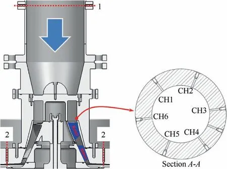
Fig. 4 Cross-section of tested compressor stage, with performance measurement positions upstream (1) and downstream (2)and pressure transducers distributed circumferentially.
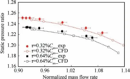
Fig. 5 Numerical and experimental static pressure ratio of compressor with tip clearance of 0.32% and 0.64% chord length.
2.4. Validation of numerical results
The simulated and experimental static pressure ratios as a function of normalized mass flow rate at two tip clearances sizes (τ=0.32%Cand τ=0.64%C) are shown in Fig. 5.The tip clearance size was taken with a feeler uniformly for four times and then the average value was calculated. During experimental tests, the data of case with tip clearance of 0.16% chord length (small tip clearance) were not measured in case of safety. Only numerical results of this case were obtained to study the effect of small tip clearance on compressor performance. In Fig. 5, the solid circle scatters and solid rectangle scatters with error bars represent the experimental results, which are identified by ‘‘τ=0.32%C_exp” and‘‘τ=0.64%C_exp”, respectively. The red dotted curve and black dotted curve represent the numerical results, which are identified by ‘‘τ=0.32%C_CFD” and ‘‘τ=0.64%C_-CFD”.Fig.5 clearly displays that the numerical trend of static pressure ratio over operating points matches well with the experimental data. Besides, the mass flow rate simulated at NS condition is a little smaller than the experimental data,but within the measurement uncertainties. There is a slight pressure ratio discrepancy between the numerical and experimental results due to the non-uniform circumferential tip clearance sizes. However, the relative errors of static pressure ratio between the numerical and experimental results are less than 0.3%. In a word, the numerical results can well predict the compressor performance.
3. Stall inception with SC at various tip clearance
To decide whether a compressor is suitable for applying ASCT, it is necessary to understand the stall mechanisms of the compressor. There are two kinds of stall routes: one is the end-wall stall, i.e. spike stall; the other is the blade stall.In the end-wall stall configuration, one can see that there is large amount of low velocity fluid or backflow, which is associated with end-wall boundary layer on the casing,accumulating in the rotor tip region at NS condition; while in the blade stall case,the separation on the blade SS is large over an appreciable fraction of span away from the end-wall. No matter which type of stall occurs,large amount of fluid with low axial momentum assembles in the tip region or attaches to the SS.
Previous studies by Greitzerand Kauet al., indicated that casing treatment can extend the SM when a compressor undergoes the end-wall stall, instead of the blade stall. Therefore,the low velocity flow in the blade passage at the last stable operating point was examined for the simulated compressor under three tip clearances to distinguish the stall routes.Fig.6(including three subfigures)shows the time-averaged isosurface on the level of streamwise velocity equalling 0.It is colored in purple with end-wall Pressure (P) contour lines at individual NS1 point. The trough of pressure contour lines presents the trajectory of tip leakage vortex.The region enveloped by the isosurface represents the flow with negative streamwise velocity, which is mainly caused by the tip leakage flow near the LE and the reversed flow near the Trailing Edge(TE). It can be observed clearly that there is no separation on the SS, and that obvious spillage ahead of rotor LE plane can be found for the cases with medium and large tip clearances.For small tip clearance, there is no spillage front of the rotor LE plane except for casing corner reversed flow near TE.Hewkin-Smithand Pullanet al. pointed out that two causes, responsible for the end-wall stall compressors, trigger the high incidence of spike-type stall inception, which is one is the blockage resulting from casing-suction-surface corner separation when the tip clearance is small, which is the case for the studied compressor with small tip clearance (as shown in Fig. 6(a)). The other is the spillage of tip-leakage flow in front of the LE plane of a rotor with large tip clearance,which is the case for the medium and large tip clearances (as shown in Fig. 6(b) and (c)). It is accordingly inferred that the mixed-flow compressor would stall through spike-stall inception regardless of the tip clearance size.
To further prove this presumption, Fig. 7 and Fig. 8 show the measured casing pressure signals,indicating the circumferential propagation of stall inceptions at medium and large tip clearances.The black and colored curves represent the original and filtered pressure signals, respectively. The experimental studies were only conducted for the compressor with the medium and large tip clearances in case of the collision between the blade tip and compressor casing under the tight tip clearance.It can be seen from Fig. 7 that compressor with medium tip clearance stalls through a classic spike stall inception. The initial spike disturbance is captured by CH5 at the time T=1850 rotor revolution, with the propagating speed of approximately 88.6% rotor speed. After propagating 1-2 revolutions, the spike disturbance grows into an obvious stall cell, then the compressor quickly enters into deep stall. As shown in Fig. 8, the compressor also stalls through the spike stall inception at large tip clearance. The initial spike disturbance is captured by CH4 at the time T=1936 rotor revolution. The propagating speed of the spike stall inception is 81.3% rotor speed. Within 2-3 revolutions, the spike stall inception develops into a large stall cell. These experimental results verified the previous presumption that the compressor with either a medium or a large tip clearance would stall through the spike stall inception. It means that the addition of casing treatment would effectively improve the stall margin of the mixed-flow compressor with each tip clearance size.
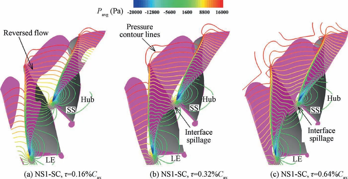
Fig.6 Rotor passage isosurface with time-averaged streamwise velocity equal to zero and pressure contour lines under NS1 conditions at 30000 r/min.
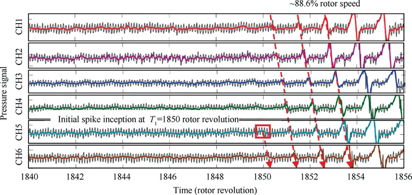
Fig. 7 Experimental stall inception signals with SC at medium tip clearance at 30000 r/min.
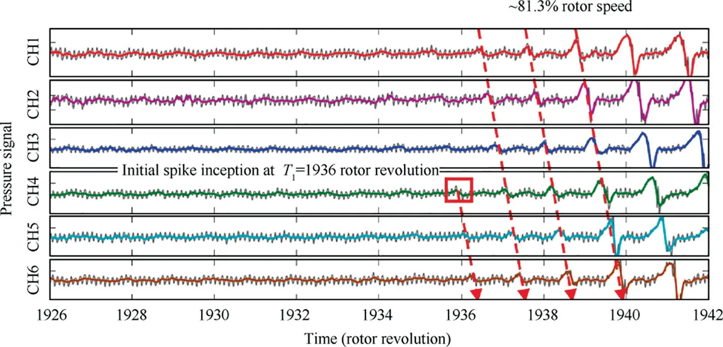
Fig. 8 Experimental stall inception signals with SC at large tip clearance at 30000 r/min.
4. Performance curves with and without CT at various tip clearances
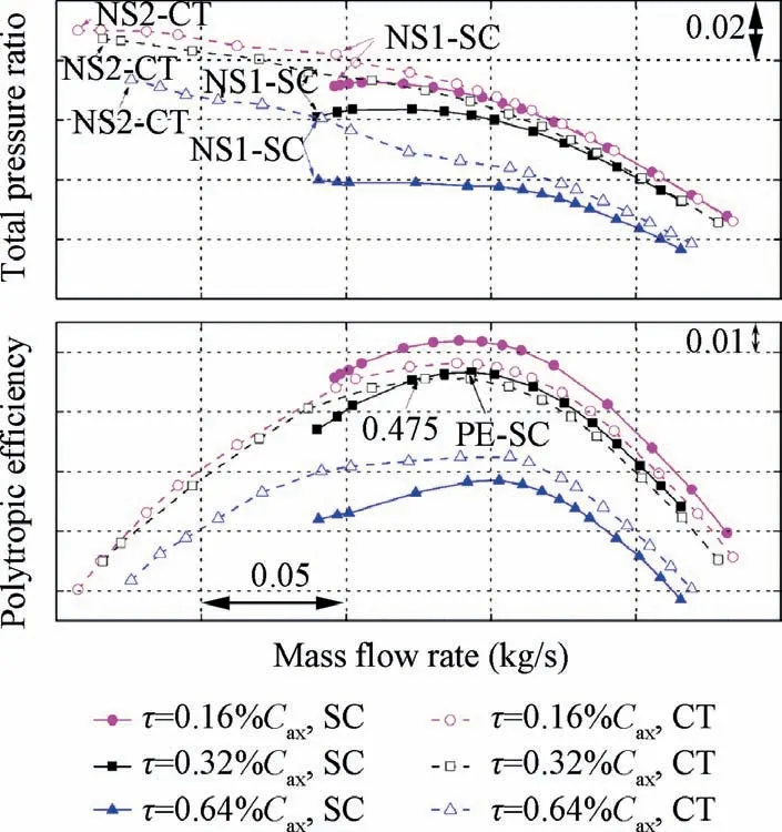
Fig. 9 Performance maps of compressor with and without ASCT at different tip clearances.
As discussed above, many researchers have found that the Peak Efficiency (PE) of a compressor decreases after applying ASCT. However, there are also some examples showing that the ASCT can both improve the efficiency and extend the SM.In this paper,the authors also believed that tip clearance size is another key factor influencing trend of variation of compressor performance when the ASCT is applied. Fig. 9 shows the performance maps of the compressor with and without the ASCT at various tip clearances. The arrows labeled with‘‘NS1-SC” represent the NS points. The arrow labeled with‘‘PE-SC” represents the peak efficiency point of the compressor with SC under medium tip clearance. Arrows labeled with‘‘NS2-CT”mean the NS points of the compressor with ASCT.One can observe that both the total pressure ratio over the whole operation range and the SM are improved by the ASCT for all the three tip clearances. The trend of ASCT-induced variation of efficiency with tip clearance is more complicated.The polytropic efficiency at each operating point is deteriorated by the ASCT under small tip clearance, but is improved under large tip clearance.For the compressor with medium tip clearance, the efficiency curves with and without ASCT intersect with each other at mass flow rate of 0.475 kg/s. At the operating points larger than 0.475 kg/s,the efficiency decreases because the loss of tip flow is magnified by the ASCT;at mass flow rates smaller than 0.475 kg/s,the efficiency is increased by the ASCT because the flow field in the original tip clearance is improved.
The results in Fig. 9 indicate that the total pressure ratio and efficiency are dramatically deteriorated when the tip clearance gets larger. This trend of variation is consistent with the previous studies on low-speed axial compressorsand on transonic fans. However, unlike the results on axial compressors,the impact of tip clearance on the mass flow rate at the NS points is relatively slight for the mixed-flow compressor, especially when tip clearance increases from medium tip clearance to large tip clearance, whose variation trend also can be found from experimental tests in Fig. 5. In order to quantitatively assess the effect of tip clearance on the compressor performance, the SM and PE for different tip clearance sizes are extracted from Fig. 9, and plotted in Fig. 10. The black and red bars represent the PE and SM, respectively.The SM is defined as follows:

where πis the total pressure ratio; ˙m is the mass flow rate;the subscripts PE and NS identify peak efficiency and near stall conditions. As for the SM, it is obviously affected by the tip clearance size. The SM increases from small tip clearance to medium tip clearance, and then decreases from medium tip clearance to large tip clearance.The trend of SM varying with tip clearance implies that there is an optimum tip clearance under which the stall margin is the largest. Whereas, the PE approximately linearly decreases when the size of tip clearance is increased. This is mainly because tip leakage flow becomes stronger causing more losses in the blade passage.
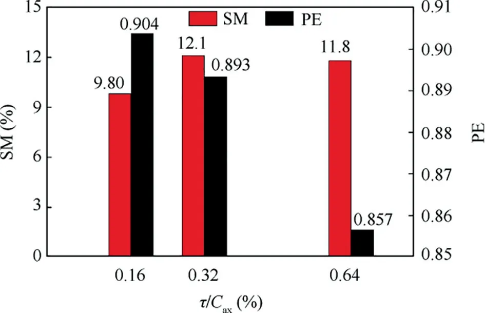
Fig. 10 Stall margin and peak efficiency of compressor with different tip clearances.
In Fig. 9, one also can clearly observe that the SM of the compressor is extended effectively. To quantify the effects of ASCT on the compressor with different tip clearances, two other parameters are defined based on Fig. 9 and plotted in Fig. 11 as a function of normalized tip clearance: SMI and PEI:

In these equations, η is polytropic efficiency. For the PEI,one can observe clearly that it increases linearly from negative values to positive value when the tip clearance size is increased.Therefore,a critical tip clearance should exist,under which the peak efficiency can keep unchanged or be improved when the ASCT is applied to the compressor.This may provide a guideline for choosing the tip clearance size in a bad stability compressor with the ASCT. For the SMI, one can observe that it decreases continuously with increasing tip clearance size, but all the SMI values are larger than 20%.
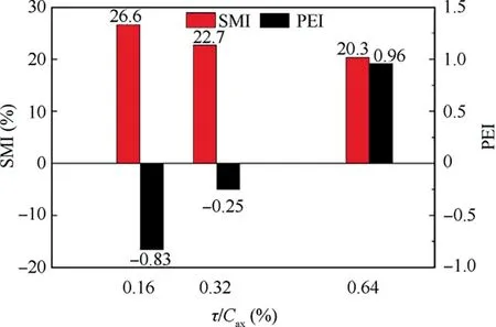
Fig. 11 SMI and PEI of compressor with ASCT when tip clearance varies.
5.Dual mechanisms of extending stall margin with CT at various tip clearances
5.1. Impact of ASCT on tip clearance flow structures
Previous results indicated that stall mechanisms of spike-stall compressor were determined by tip clearance size.This enlightened us that the dominant stability enhancement mechanisms may be determined by tip clearance size. Undoubtedly, the application of ASCT directly exerts influences on flow structures and thus extends the stall margin. Hence, the impacts of ASCT on tip clearance flow were investigated at two tip clearance sizes in the following. What should be emphasized is that the flow structures for both medium and large tip clearances are similar; therefore, only flow structures under small and large tip clearances are shown.
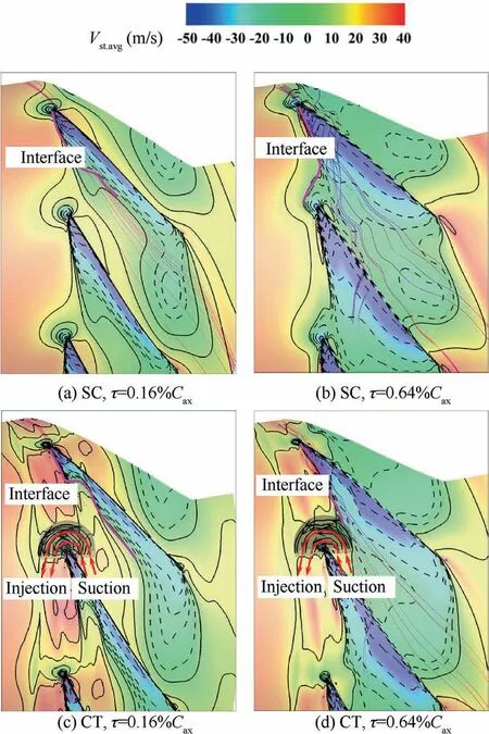
Fig.12 Time-averaged streamwise velocity in tip region at NS1-SC condition.
To assess how ASCT interacts with tip clearance flow fields,the contours of streamwise velocity in the tip region (99.5%span) are plotted in Fig. 12 (including four subfigures). The flow structures in the compressor with and without the ASCT under the two tip clearance sizes are shown at respective NS1 conditions. To accurately show the contours, the timeaveraged streamwise velocity (V) are extracted from unsteady simulation results. The flow structures in the left and right columns are extracted from the cases with small and large tip clearance sizes, respectively. The first row is for the compressor with SC; the second row is for the compressor with the ASCT configuration.The solid contour lines mean the flow region with positive streamwise velocity;while the dashed contour lines represent the flow area with negative streamwise velocity.The transparent gray semi-circle represents one of the four slots per blade passage. A series of streamlines are released in the semi-circle to illustrate the flow transportation between blade passage and axial slots.One can clearly see that the suction and injection flow is formed in the axial slots,which is also called the ‘‘suction and injection effects” generated by the axial slots, as indicated in previous studies on ASCT.The suction effect means that the blocked fluids in the tip clearance region is removed or sucked from blade passage into axial slots; the injection effect means the flow inside the slots is injected into blade passage. The purple curves labeled character ‘‘interface” indicate the location of interface between incoming main flow and tip leakage flow, which is identified by zero streamwise velocity.
By comparing Fig.12(a)and Fig.12(c),for the compressor with small tip clearance, it can be seen that the interfaces between incoming and tip leakage flow are still in the blade passage regardless of whether the ASCT is added or not.Khalid et al.proved that the trajectory of incoming/tip leakage flow interface is the balance of streamwise momentum between incoming main flow and tip leakage flow. The tip clearance is so small that the tip leakage flow with negative streamwise momentum is too weak to resist the incoming main flow. As a result, the interface is still in the blade passage for the case with SC. In this scenario, the compressor stalls due to the blockage caused by reversed flow in the casing-suctionsurface corner, which echoes the results in Section 3. When applying ASCT, the blocked fluid underneath the slots is sucked into axial slots.Hence,the blockage region represented by black dashed contour lines is curtailed by ASCT near rotor LE, which is beneficial to achieving wider operating range.
By comparing Fig. 12(b) and Fig. 12(d), one can clearly observe the effect of ASCT on tip clearance flow field for the compressor under large tip clearance. As shown in Fig. 12(b), the interface between tip leakage flow and incoming main flow spills out of blade passage ahead of rotor LE at the nearstall point for the case with SC, which would cause the spiketype stall inception,as validated by the experimental results in Section 3. No wonder that the streamwise velocity of nearcasing fluid at the inlet of rotor is negative (as shown in Fig. 6(c)). When applying the ASCT on the compressor, as shown in Fig. 12(d), the interface between tip leakage flow and incoming main flow moves downstream towards to the rotor TE, which would delay the spillage of interface ahead of rotor leading-edge plane and is responsible for the stall margin improvement with ASCT.It is also observed that the injection flow from the slot accelerates the incoming main flow.Hence, the streamwise velocity and momentum of incoming flow increase notably at the inlet of rotor, which would make the boundary layer thinner and attenuate flow blockage near the LE of rotor. The suction flow into the slots also helps to remove the tip leakage flow with negative streamwise momentum and reduces the blockage near downstream edge of the slot accordingly.
To summarize, the circulation flow, namely the ‘‘suction and injection effects”, formed in the ASCT, alleviates the blockage in the tip region under small tip clearance and pushes the incoming/tip leakage flow interface under large tip clearance, thus extending the stall margin of the compressor for both tip clearance sizes. In the following section, we will further examine and evaluate which effect dominates the stability enhancement mechanism with ASCT at two different tip clearance sizes.
5.2. Effect of injection flow on incoming main flow
As depicted in Fig.12(c)and Fig.12(d),the injection flow into blade passage mainly interacts with the incoming main flow near rotor LE. Therefore, in order to understand how the injection flow affects the incoming flow,Fig.13 plots the spanwise distributions of the time-averaged streamwise velocity Vat the inlet of rotor with two tip clearances at the near stall condition of NS1-SC. The abscissa and ordinate mean time-averaged streamwise velocity Vand relative spanwise location h, respectively. The spanwise locations of rotor hub and casing are indicated by 0 and 1.0. In each subfigure, the sketches of velocity triangles at 0.98 spanwise location with and without ASCT are provided to reflect the effect of ASCT on relative flow angle of incoming flow in tip region,based on the time-averaged data extracted from simulation results. The solid curves represent the compressor with SC,and the dashed curves represent the compressor with ASCT. The magnitudes of velocity have been marked.
In Fig. 13(a), the intersection point of the two streamwise velocity curves for the compressor with the SC and ASCT under small tip clearance is located at 0.92 spanwise location.Above the intersection point, the streamwise velocity is decreased by ASCT; and below the intersection point, the streamwise velocity is increased by ASCT. The sketches of velocity triangle at 0.98 spanwise location are also plotted in Fig. 13(a) based on the time-averaged velocity data extracted from simulation results.βand βrepresent the relative flow angles of incoming flow for cases with SC and with ASCT at rotating reference frame, respectively. It is found that the relative flow angle of incoming flow at the inlet of rotor is increased by the addition of ASCT due to the reduced streamwise velocity. The increment of incidence angle of incoming flow can deteriorate the compressor stability under small tip clearance.
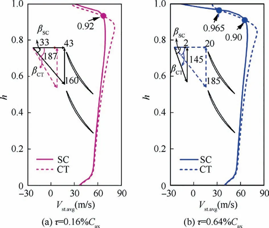
Fig. 13 Spanwise distribution of streamwise velocity at various tip clearance.
In Fig. 13(b), the two streamwise velocity curves for the compressor with SC and ASCT under large tip clearance intersect at two points, which are located at 0.965 and 0.90 spanwise locations, respectively. The effect of ASCT in the tip region (h=0.965-1) and the middle region (h=0-0.90) is more prominent than the effect in the region from 0.90 to 0.965 (h=0.90-0.965). By comparing Fig. 13(a) and Fig. 13(b), the influence of ASCT in the middle region from hub to 0.90 spanwise location under large tip clearance is similar to that under small tip clearance.The addition of ASCT increases the streamwise velocity of incoming flow, and improves the flow condition in the middle region. Different from the compressor under small tip clearance, the streamwise velocity in the tip region (shown in Fig. 13(b)) from 0.965 spanwise location to casing(h=0.965-1)is notably improved by ASCT for the compressor under large tip clearance.Taking 0.98 spanwise location as an example, the streamwise velocity is increased from 2 m/s to 20 m/s. As a result, the addition of the ASCT can push the interface between tip leakage flow and incoming main flow downstream, and the upstream spillage of interface and rotating stall can be delayed.From the velocity triangles at 0.98 spanwise location for large tip clearance,one can also see clearly that the relative flow angle of incoming flow at the rotor inlet is reduced by the addition of ASCT due to increment of streamwise velocity.
In conclusion, the injection effect generated by ASCT has negative effects on incoming main flow in the rotor tip region,which can deteriorate the compressor stability under small tip clearance. However, the injection effect caused by addition of ASCT notably improves the incoming flow in the tip region near casing, which can push the interface between tip leakage flow and incoming main flow downstream and enhance the compressor stability under large tip clearance.
5.3. Effect of suction flow on tip leakage flow and blade tip loading
To further explore the effect of suction flow generated by ASCT on tip leakage flow, Fig. 14(a) and Fig. 14(b) provide the streamwise velocity distributions of tip leakage flow as a function of normalized axial location for the cases with SC and ASCT under two tip clearances. The abscissa of 0 and 1 indicate the locations of rotor LE and rotor TE, respectively.The streamwise velocity of tip leakage flow in Fig. 14 is extracted at the radial position (marked with τ/4), which is located at 0.25 times of tip clearance size away from the compressor casing.The solid curves represent the data for the compressor with SC and the dotted curves represent for the compressor with ASCT.The axial range covered by axial slots is indicated by black lines with double-headed arrows. The filled semi-circles represent the axial slots over the compressor rotor.The character‘‘TE of slots”means the TE of axial slots.
It should be noted that the streamwise velocity of tip leakage flow is negative because the flow direction of tip leakage flow is opposite to the incoming main flow. Hence, the decrease and increase of the streamwise velocity mean that tip leakage flow is strengthened and attenuated, respectively.
As shown in Fig. 14(a) for the compressor under small tip clearance, the streamwise leakage velocity from rotor LE to axial location of 0.65 is increased. Due to the suction effect of slots (as shown in Fig. 12(c)), the increment of streamwise leakage velocity from rotor LE to ‘‘TE of slots” is more notable.While,the tip leakage streamwise velocity is reduced in the region aft of axial location of 0.65. It means that the tip leakage flow is attenuated in the tip region from rotor LE to axial location of 0.65, and is strengthened from axial location of 0.65 to rotor TE.
To understand the results shown in Fig. 14(a), Fig. 15(a)presents the time-averaged pressure distributions on the Pressure Side (PS) and Suction Side (SS) of rotor blade along the axial location at 97% span with and without ASCT under small tip clearance. As shown in Fig. 15(a), in the tip region from rotor LE to ‘‘TE of slots”, the pressure on the blade SS decreases, leading to larger pressure difference between PS and SS. In the tip region downstream of the slots, the static pressure on the PS increases,while the pressure on the SS stays unchanged along the axial direction. As a result, the pressure loading along the whole blade tip is enhanced by the ASCT.
Previous studieshave proved that the tip leakage flow is driven by pressure difference between the PS and SS of rotor blade for the compressor with smooth casing. However, by comparing Fig. 14(a) and Fig. 15(a), one can conclude that the tip leakage flow is not only driven by the pressure difference across the blade tip between the blade PS and SS,but also substantially affected by the suction effect of ASCT for the compressor with casing treatment. In the region from rotor LE to ‘‘TE of slots”, the suction flow entering into the slots removes a large amount of blockage in the tip region, leaving more spaces for the incoming main flow in the blade passage(as shown in Fig.12(c)).As a result,the tip leakage flow in this region is suppressed even though the pressure loading shown in Fig.15(a)is increased.In the tip region unaffected by ASCT from axial location of 0.65 to rotor TE, it is observed that tip leakage flow is directly driven by the pressure difference between blade PS and SS. Tip leakage flow in this region with greater negative streamwise velocity is enhanced by the increased pressure loading. This phenomenon is responsible for the large amount of tip end-wall blockage near the blade TE (as shown in Fig. 12(c)).
As depicted in Fig.14(b)for the compressor under large tip clearance, in the area from rotor LE to axial location of 0.5,the streamwise leakage velocity is increased due to the blockage reduction in the tip region generated by the suction effect of ASCT.In the region from axial location of 0.5 to rotor TE,the streamwise leakage velocity is reduced, which would lead to stronger tip leakage flow and serious blockage area near blade TE in the tip region (as shown in Fig. 12(d)). Through comparing Fig. 14(a) and Fig. 14(b), one can observe that the suction effect of ASCT on the streamwise leakage velocity distributions is similar but weaker than that for the case under small tip clearance.It is no doubt that both the mass flow rate and momentum of the tip leakage flow would increase when the tip clearance size is enlarged. With the same configuration of ASCT, the interaction of ASCT with tip clearance flow would be weaker. It is no wonder that the streamwise leakage velocity is slightly changed by the ASCT when tip clearance size is large.
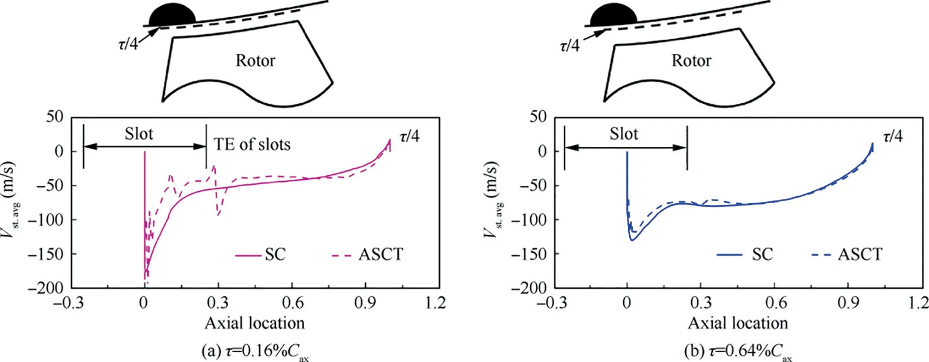
Fig. 14 Streamwise leakage velocity distributions of compressor with and without ASCT.
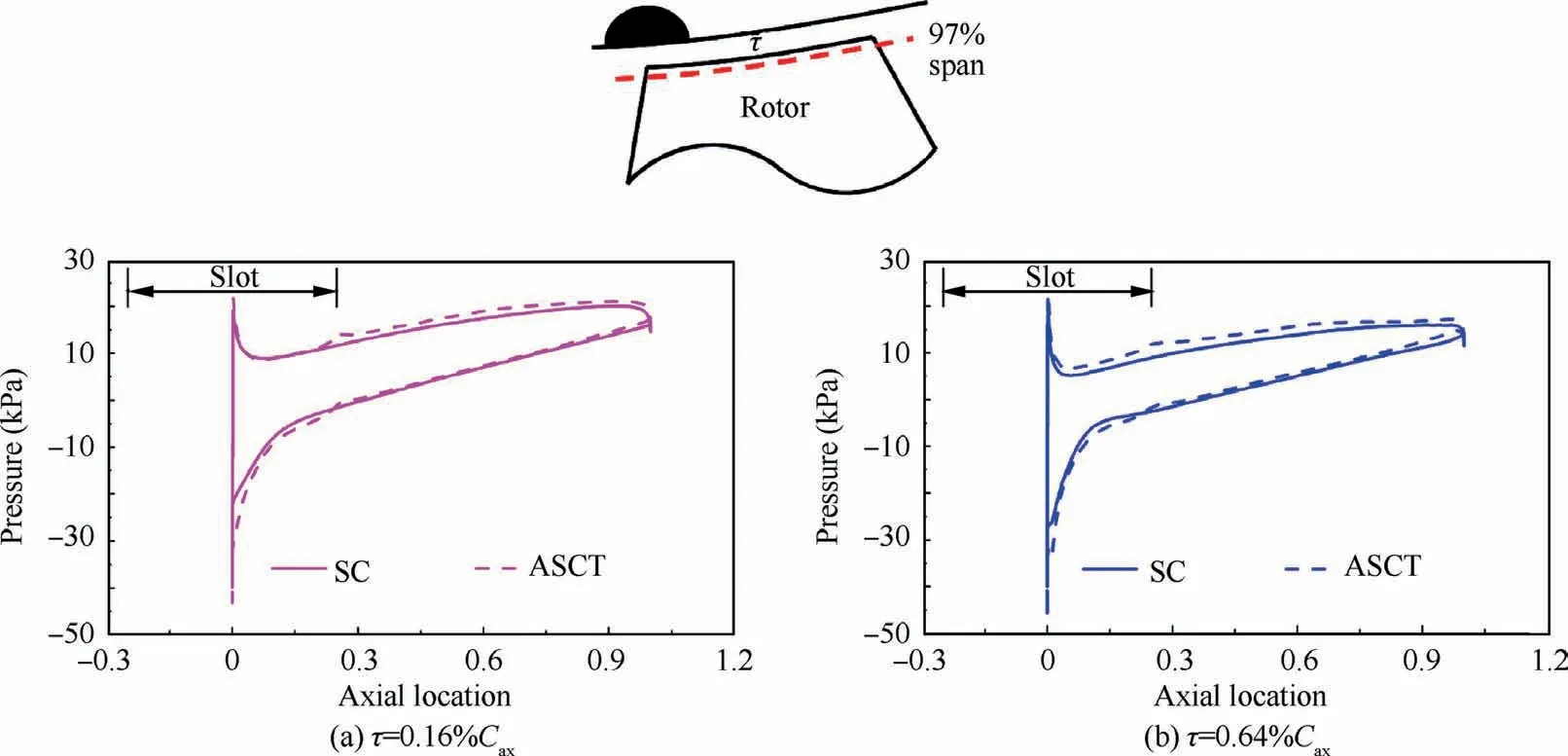
Fig. 15 Pressure distributions at 97% span of rotor.
Fig. 15(b) further provides the time-averaged pressure distributions on the PS and SS of rotor blade along the axial location at 97% span with and without ASCT under large tip clearance.It can be seen that the pressure on PS increases from rotor LE to rotor TE;while the pressure on SS decreases from rotor LE to the axial location of 0.2 and increases slightly downstream of the axial location of 0.2. As a result, the pressure difference is enlarged along the whole blade tip chord by the ASCT.The finding summarized from the case under small tip clearance, that the strength of tip leakage flow along the whole rotor blade chord with ASCT does not always coincide with the distribution of pressure loading at the blade tip, is again verified by the data with large tip clearance.The tip leakage flow in the tip region under the impact of ASCT is mainly determined by the suction flow induced by the axial slots. In the region unaffected by axial slots, especially near the blade TE,the streamwise leakage velocity is consistent with the variation of pressure loading for the compressor with ASCT.
In conclusion,the interaction mechanism of ASCT with tip leakage flow varies with the size of tip clearance.For small tip clearance,the suction flow contributes more to attenuating tip leakage flow than the injection flow, because the streamwise leakage velocity is reduced from the LE of rotor to the location at more than half tip chord length,and the streamwise velocity of incoming flow at LE of the rotor is decreased in the area above 0.92 span (as shown in Fig. 13(a)). The latter influence leads to a higher incidence angle,which is harmful to compressor stability. In contrast, for large tip clearance, the contribution of suction flow to attenuating blockage in the tip region is comparatively weak, because the tip leakage flow is just slightly attenuated. The injection flow out of the slots plays a more important role in pushing the interface between tip leakage flow and incoming flow downstream (as shown in Fig. 12(d)),thus delaying the spillage of tip leakage flow ahead of the rotor LE plan. This is the dominant stability enhancement mechanism with ASCT for the compressor under larger tip clearance. This point is also supported by the fact that the streamwise velocity near the casing is changed by the ASCT from a negative value to a positive value in the case with large tip clearance (as shown in Fig. 13(b)).
6. Conclusions
In this study, the effect of a semi-circle ASCT on the performance of a mixed-flow compressor with three different tip clearances (0.16%, 0.32% and 0.64% chord length) at 30000 r/min and stability enhancement mechanism of ASCT at various tip clearances were studied using steady and unsteady simulations. The main conclusions are summarized as blow:
(1) Stall inception type of the compressor at various tip clearances: The experimental results show that the compressor stalls through spike-stall inception at the medium and large tip clearances. For these two tip clearance configurations,the numerical results show that the spike-stall inception is caused by the spillage of interface formed by incoming flow and tip leakage flow.Although there are no experimental results for the compressor with small tip clearance, the numerical results show the compressor stalling under small tip clearance is caused by casing-suction-surface corner separation,which is the other flow characteristic leading to endwall stall and spike-stall inception.
(2) The impact of tip clearance size on the compressor performance: Without ASCT, consistent with current knowledge, the peak pressure ratio and efficiency decrease with the increase of tip clearance. The stability is improved firstly and then decreased when the tip clearance increases, which means an optimum tip clearance should exist for compressor stability. The ASCT has a significant effect on the compressor performance under all the tested tip clearances.Although the peak efficiency is deteriorated by the ASCT in the cases with small and medium tip clearances, the peak efficiency increases in the case with large tip clearance. There should be a critical tip clearance under which the peak efficiency keeps unchanged or increases. The ASCT can improve the compressor stability for all the tip clearances investigated, and the SMI decreases as the tip clearance is enlarged.
(3) Stability enhancement mechanism of ASCT in the compressor under small tip clearance (0.16% chord length):the addition of ASCT generates circulation flow in the axial slots, and alleviates the blockage in the tip region accordingly. The circulation flow exerts suction and injection effects on the tip clearance flow in the compressor. The injection effect of ASCT decreases the streamwise velocity and hence increases the incidence angle of incoming main flow at the inlet of rotor in tip region,which is harmful to the compressor stability.The suction effect of ASCT attenuates the strength of tip leakage flow,and reduces the blockage caused by the tip leakage flow near rotor leading edge. Therefore, the suction effect is considered as the dominant stability enhancement mechanism with ASCT for the compressor under small tip clearance.
(4) Stability enhancement mechanism with ASCT in the compressor with large tip clearance (0.64% chord length): for the compressor stalling through salient spike-stall inception under large tip clearance,the mechanism of stability enhancement is associated with the behavior of interface between tip leakage flow and incoming main flow,which is determined by the streamwise momentum balance between the two flows. The injection effect generated by the addition of ASCT notably increases the streamwise velocity, i.e. streamwise momentum of incoming main flow in the tip region near casing, which can contribute to pushing the interface between tip leakage flow and incoming main flow downstream and enhance the compressor stability.The suction effect of ASCT reduces the streamwise momentum of tip leakage flow that is opposite to the incoming main flow,although the effect of weakening tip leakage flow is not as obvious as that under small tip clearance. Therefore,both the suction and injection effects produced by ASCT play important roles in enhancing stability of the compressor under large tip clearance.
The above findings revealed the notable impact of tip clearance size on the performances and stability enhancement mechanisms with ASCT on a high-speed mixed-flow compressor.It means that tip clearance size is a significant factor which engineers should consider when assessing the performance of ASCT for compressors. It is quite crucial to understand the dominant stability enhancement mechanism with casing treatment when designing axial slots for a compressor with a specific tip clearance.There might be a critical tip clearance size for each compressor.When the applied tip clearance is lower than the critical tip clearance size,the‘‘suction effect”that occurred near the downstream edge of the axial slots plays the leading role in enhancing compressor stability. It implies that one should put emphasis on optimizing the geometry of rear part of axial slots, which would affect the suction flow into slots and improve the stall margin more obviously than modifying the geometry of front part of axial slots.On the contrary,when the tip clearance larger than the critical tip clearance size is applied for the compressor, the ‘‘injection effect” might be the key reason responsible for the stall margin extension.One should pay more attention to optimizing the geometry of the front part of axial slots, which can efficiently energize the incoming main flow and improve the stall margin of the compressor. Therefore, it is very meaningful to find out the method of determining such a critical tip clearance size for compressors, which is the next step of this work in the near future.
Declaration of Competing Interest
The authors declare that they have no known competing financial interests or personal relationships that could have appeared to influence the work reported in this paper.
Acknowledgement
sThis work is funded by the National Science Foundation of China (Nos. 51676184, 51636001 and 51922098),the National Science and Technology Major Project (Nos. 2017-II-0004-0017 and 2017-II-0005-0018),and the National Key R&D Program of China (No. 2018YFB0606100). The authors also express their gratitude to Felix Kauth and professor Joerg R.Seume for their kindness of sharing the experimental data and would like to thank the German Research Foundation(DFG) for supporting the experiments as part of the Collaborative Research Centre 880.
 CHINESE JOURNAL OF AERONAUTICS2021年4期
- CHINESE JOURNAL OF AERONAUTICS的其它文章
- Time delay compensation in lateral-directional flight control systems at high angles of attack
- Development cost prediction of general aviation aircraft using combined estimation technique
- Improvement on shaped-hole film cooling effectiveness by integrating upstream sand-dune-shaped ramps
- Modeling and parameter identification of linear time-varying systems based on adaptive chirplet transform under random excitation
- An experimental method to obtain the hard alpha anomaly distribution for titanium alloy aeroengine disks
- Vibration analysis and control technologies of hydraulic pipeline system in aircraft: A review
