Investigation of a plasma delivery system for optical figuring process
Nan YU, Rnaud JOURDAIN, Maro CASTELLI, Adam BENNETT,Jiang GUO, Chngyu MA, Fngzhou FANG
a Centre of Micro/Nano Manufacturing Technology (MNMT-Dublin), University College Dublin, Dublin 4, Ireland
b Manufacturing Technology Centre (MTC), Coventry CV7 9JU, UK
c Surface Engineering and Precision Institute, Cranfield University, Bedford MK43 0AL, UK
d Key Laboratory for Precision and Non-traditional Machining Technology of Ministry of Education, Dalian University of Technology, Dalian, China
e Department of Aeronautics, Imperial College London, London SW7 2AZ, UK
f Ningbo Institute of Dalian University of Technology, Ningbo 315016, China
KEYWORDS Inductively coupled plasma;Plasma delivery system;Plasma etching;Radio frequency network
Abstract Plasma figuring process enables the correction of metre-scale optical surfaces,which has advantages such as rapid convergence to ultra-precision accuracy level,no subsurface damage,ease of upscale thanks to the conditions of operation at atmospheric. Such attributes make plasma figuring a highly competitive technology.To maintain a stable discharge of plasma for long period,a robust Plasma Delivery System(PDS)is required for large optics manufacturing.A dedicated PDS,mainly based on an L-type radio frequency(RF)network and an inductively coupled plasma(ICP)torch, had been previously proposed and designed. This study addresses the requirement for improving the robustness and securing the performance of the plasma etching.Due to the complexity of interactions of PDS parameters, single variable optimization is conducted for adjusting the impedance of the plasma torch.The PDS optimization is analysed based on ignition power demand,test repeatability and reflected power values. The results show that reflected power values are controllable within 10 W, when the RF power is supplied from 200 W up to 800 W. Finally, plasma processing is carried out on fused silica glass, using the optimum parameters of the PDS.
1. Introduction
Large optical fabrication requires rapid figuring processes targeting ultra-precision form accuracy of one part in 10, and ultra-smooth surface at nanometre level.Plasma figuring processes present great advantages of super-high efficiency, low cost and no surface stress.These make the process competitive towards the current state-of-the-art figuring processes,such as ion beam figuring (IBF),magnetorheological finishing(MRF),and robotic polishing.Unlike the ion beam, which uses high-energy ions sputter the sample,in plasma figuring process the reactive gas is atomized in an argon plasma into free fluorine radicals, so that the plasma jet can then dryetch silicon-based materials.Therefore,this noncontact plasma enhanced chemical process can produce the desired form accuracy of an optic through deterministic localised material removal. Moreover, plasma figuring is operated at atmospheric pressure, so it is easy to be scaled-up as there is no restriction of vacuum chamber. This offers the potential of a very cost-effective process for the mass production of large optics.
Plasma figuring processes on various optical surfaces were previously demonstrated using mainly three types of plasma generation methods, e.g. microwave induced plasma (MIP),capacitively coupled plasma (CCP) and inductively coupled plasma (ICP).MIP and CCP are mostly used for small size optics (smaller than 100 mm in diameter) and typically work with a microwave power of 60 W and an RF power of 150 W. An ICP jet is normally developed with much higher RF power(i.e.a few kW),and is therefore considered efficient for large optical fabrication.For instance,an 0.4 m optical surface was successfully corrected by ICP figuring,associated with advanced tool path algorithm. In that work, the process was carried on a ULE glass substrate and a form accuracy of 31 nm RMS was obtained with duration of 2.5 h.It could reasonably be inferred that figuring of a 1 metre mirror requires at least 10 hours.Therefore,the industrial application of the ICP figuring demands a plasma delivery system (PDS)that is stable and robust over such a period of time.
Previous studies on ICP plasma figuring development improved the gas flow properties of plasma jetsand heat transfer efficiencies.Fig.1(a)shows the experimental setup of plasma figuring tool discussed in this study. The blue lines demonstrate the simplified gas paths: The carrier gas (Ar)and secondary gas (Ar mixed with CFor SF) are controlled by MFCs (mass flow controllers). The secondary gas is feed into the inner tube(Fig.1(b)),which is coaxial to the auxiliary tube and outer tube that feed with carrier gas. The black lines in Fig.1(a)outlines the architecture of the PDS,including RF generator, RF network and the ICP torch. This study will focus on the parameter optimisation of the PDS.
2. Design of dedicated PDS
The description of the PDS in this study can be divided into two parts:fixed matching RF network(including transmission line, RF signal generator), and ICP torch. In this section, the key components and the parameters settings optimisation are introduced. The design principle aims at achieving a robust plasma generation with performance indicators such as stability of the RF frequency, easiness of the plasma ignition, and reduced power reflected to the RF generator.
2.1. Fixed matching RF network
In the considered RF network, the impedance includes transmission line resistance, capacitors, and induction coil. The transmission line consists of a number of adapters,connectors and coaxial cables,which is an N-N male cable coax(RG142).To ensure the appropriate power transfer, a low-impedance transmission line is properly selected in length. The length of this line is integral multiple 1/4 wavelength (λ) from the RF generator that could be expressed in Eq. (1).

where,v represents the speed of the RF signal wave,f is the frequency of RF signal.c is the speed of light,α is the velocity factor of the coax cable. Values can be given as, f=40.7×10Hz, which is the average frequency from the RF generator;c=3×10m/s; α=69%, which is provided with the generator.
Two spiral capacitors (CVBA-250AC/15-BEA-L, Comet Technologies USA, Inc.) are adopted in this RF network,including a tune capacitor and a load capacitor.The resolution of capacitance tuning is 0.14 pF, which is 1% of a full turn of the knob. Accordingly, 0.07% is changed in tune capacitance and 0.5% in load capacitance with the minimum tuning(0.14 pF).The original settings of the RF network in this study are ~40 pF for load capacitor and ~215 pF for tune capacitor.
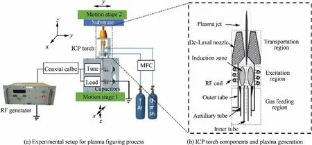
Fig. 1 Inductively Coupled Plasma (ICP) figuring technology.
Frequencies data can be obtained from the RF power supply (CV2000, Comdel, Inc.). The output power is up to 2 kW,while its output frequency is 40.68±2 MHz,which is 3×multiple of 13.56 MHz. This water-cooled generator is associated with frequency agile tuning technology,together with a load of 50 Ω.For safety reason,the reflected power(RP)is set with a limitation up to 10% of the forwarded power (FP). Associated with sensors,the generator could measure the RF current,voltage, FP from the source RF generator to the impedance matching network, and the RP from the RF network back to the generator. The power delivered to the plasma is equal to FP minus RP. The RF power in this manuscript refers the power delivered to the plasma.Therefore,impedance matching is critical in the RF network, as maximum power transfer is required from the RF generator to the ICP torch coil.It would damage the power supply if the reflected power is over 10%of the forwarded power.In a previous study,a motorized RF network was design previously to address the three phases during the plasma operation,i.e.ignition,regular operating,and critical circumstance.One focus of this study is on the influence of the capacitances on the plasma generation.
2.2. RF-ICP torch
TheICPtorchunderthisinvestigationcomprisesthreeregionsas showninFig.1(b).Inthegasfeedingregion,stableflowrateofAr gas and reactive spices are supplied and divided into three streams. In the excitation region, gas is excited and ionized in the time-varying electromagnetic (EM) field, generated from the RF-powered induction coil. The plasma jet transportation region includes a copper nozzle and the space between the water-cooled nozzle and the workpiece.The plasma temperature is ~10000 K in the excitation region and reduced to ~1000 K when passing through the nozzle.This nozzle with internal convergent-divergentgeometrycanadjusttheprocessingparametersoftheplasmajet,e.g.velocityoftheflow,distributionsofgas temperatureandreactivespices’concentration.Characterization of the nozzle has been investigated in previous studies,while the one of the focus of this study will be on another critical component,i.e.helical RF coil.
The RF coil is supplied with alternating current, so as to create the desired varying EM field, hence generate free electron cascade (Fig. 1(b)). The induction coil is made with hybrid structures: 3 turns closed and 2 turns open (Fig. 2),which could trigger the ionization sequence without using a Tesla unit for the quick discharge. This design is considered suitable for the large optical fabrication in which the plasma delivery system moves with high dynamic requirement. The performance of the coil on effective energy transfer are mainly determined by its material, position and geometry. The base metal of the coil is copper with silver plating, which is considered the most efficient conductor of the RF power.The position of the coil, including relative to the quartz tube and the nozzle, determines if the plasma generation is correctly distributed.In this study,the material and position of the coil will not be changed during the optimisation and will be kept with same material in the consistent position,although the selection and maintenance of the coil will be discussed later.As a critical part of the RF circuit, the coil geometry will be adjusted by changing the diameter of the winding and the pitch spacing(Fig. 2(b)). Hence, the influence of the changes in coil inductance can be investigated.
The geometry of the coil in this study is demonstrated in Fig. 2(a). A unique design of this coil comparing with the ICP coils commonly used,is reflected on an open coil tail,which is named free turns in this study. There are two free turns and three full loop turns in this coil, while other studies have only several turns of full loop coil. The function of this tail is to create plasma with higher density of ions and electrons and also ease the excitation of the plasma.Based on Henrys,the inductance of the coil,L,can be derived as Eq.(2).

where μ is a constant relative to the coil’s symmetry; D and l marked in Fig. 2 (b), are the diameter and length of the winding respectively; N=l/p, is the number of turns, and p is the pitch spacing.
3. Optimization of the RF parameters
The four key design parameters in the RF network and ICP torch are optimized to recommend an optimum setting for a stable PDS. The one-variable-at-a-time (OVAT) method was utilized for optimizing these parameters. This study is focused on the capacitors (tune and load), and torch coils (length)separately.
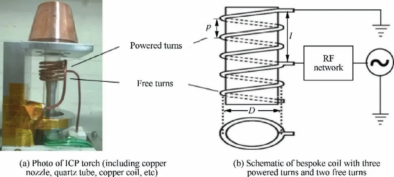
Fig. 2 ICP torch coil.
3.1. Optimization of the capacitors
A study on the effect of tune and load capacitance value was carried out. The load capacitance was fixed at 27.86 pF, and the tune capacitance was increased by ~0.8% from the base value at 197.96 pF. In each setting with specific tune and load capacitance,the frequencies at pre-ignition power(200 W)and pre-processing power (800 W) were recorded. Also, the FP at which the plasma was ignited was logged. In this way, the effect of tune capacitor on the RF frequencies and plasma ignition can be found. Then, the tune capacitance was fixed at 198.94 pF, while the load capacitor was increased by 2%.The same procedure was followed to investigate the effect of load capacitance on the RF network.Experiments were carried out in continuous three days for the repeatability test. The repeatable plasma frequencies would demonstrate the robustness of the PDS within the total duration of 900 min.The frequencies recorded at each capacitor setting were logged and are displayed in Fig. 3, while Fig. 4 illustrates the power for plasma ignition of each setting.
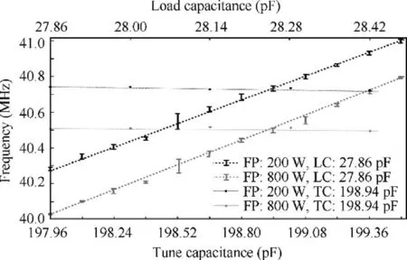
Fig. 3 Frequency recorded from RF generator versus tune capacitance and frequency versus load capacitance.
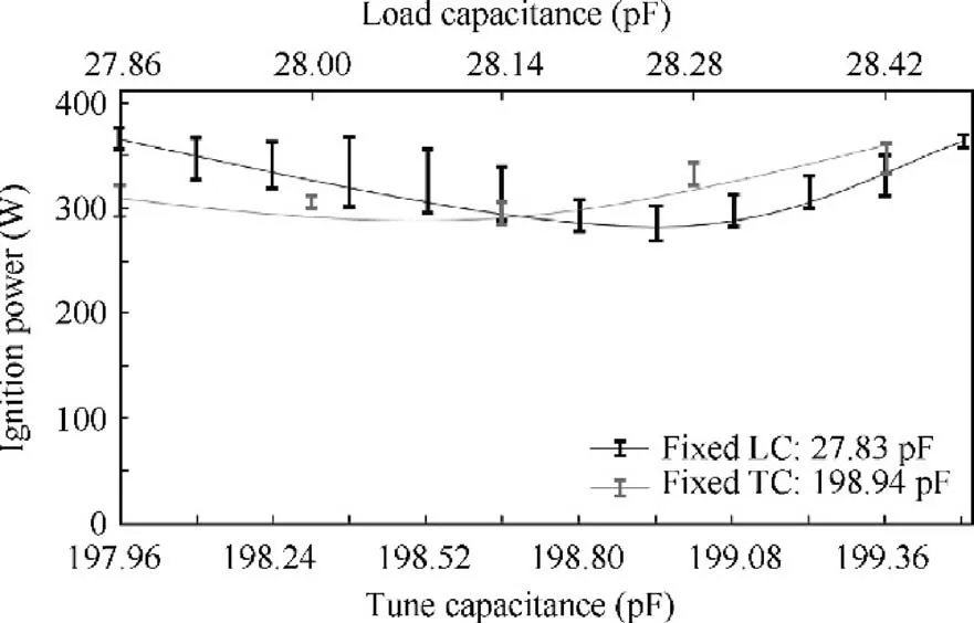
Fig. 4 Ignition power versus tune capacitance and ignition power versus load capacitance.
3.1.1. Impact on RF frequencies
The RF frequencies of varying capacitors’ combinations were studied in Ref.15.Based on the empirical practice from previous operations, 198.94 pF of the tune capacitor is fixed in this investigation as a baseline of relative low FP of plasma ignition. The deviation of the frequency (solid lines in Fig. 3) is within 0.01 MHz when the load capacitor is varied between 27.86 and 28.42 pF (increased by 2%). Data in black is obtained before plasma ignition (forward power at 200 W),while in grey is obtained at the processing power (forward power 800 W). Inversely, a linear correlation between the frequency and tune capacitance was observed as the dotted lines increases by ~1 MHz with tune capacitor varied between 197.96 and 199.50 pF (increased by ~0.8%). The frequency data was logged with specific combinations of tune and load capacitance, and three times of each combination were performed for the repeatability tests. The maximum deviation in each combination is better than 0.1 MHz, which proves the high repeatability of the PDS. The optimum frequency is not sensitive to the load capacitance but is strongly influenced by the tune capacitance. This phenomenon has been revealed in Ref. 15 for demonstrating the performance of the PDS. However, these results formed the foundation of the optimization of other parameters,so it is necessary to present it before introducing the impact on the plasma ignition.
3.1.2. Impact on the plasma ignition of the ICP torch
Fig. 4 displays the minimum and maximum logged frequency values at each permutation and combination of capacitance values.The ignition powers are averaged and fitted in the parabolic functions as shown.During the tests,plasma was ignited with FP of over 230 W. The black fitting presents the ignition power with a fixed load capacitance at 27.86 pF and varying tune capacitance between 197.96 and 199.50 pF (same as Section 3.1.1.). The plasma was easiest to be excited at 198.94 pF with the lowest ignition power of 270±40 W.The grey fitting presents that of fixed tune capacitance at 198.94 pF and varying load capacitance from 27.86 to 28.42 pF. To ease the plasma generation, the recommended combination of capacitors will be 198.94 pF(tune)and 27.86 pF(load).The priority of the recommendation is to seize the lowest ignition power but not smallest deviation. The standard deviation of the plasma ignition power for this combination setting was 15%, which is lower than that of the overall tests (17%).
3.2. Optimization of the torch coil parameters
3.2.1. Impact from the coil length
As mentioned in Section 2.2 and shown in Fig.2,the coil contains two free turns, which is made of solid copper, and three full-loop turns (hollow) powered by RF generator. Chilling water of room temperature runs through the full-loop turns to prevent the coil from melting. The length of the coil was squeezed from 25.5 mm to 23.5 mm, and then pulled back to 25.5 mm with increment of 0.5 mm using slip gauges.Both frequency (Fig. 5(b)) and ignition power (Fig. 5(b)) increased when the coil was stretched up. The lowest ignition power was achieved at 310 W when the coil length is 23.5 mm. The length was raised by up to 8%,with a corresponding frequency increase of 1.2% and ignition power increase of 15%. It was logical to keep squeezing the coil, but no ignition occurred again when it was furtherly shortened. This phenomenon was considered because of the varying EM field has no enough energy for plasma excitation. All the tests in this section were carried out with the fixed combination of load capacitance(27.86 pF) and tune capacitance (198.94 pF).

Fig. 5 Effects of coil length on frequency and ignition power.
3.2.2. Impact from the number of free turns
The effect of coil geometry was investigated for this unique torch coil design. The bespoke torch was equipped with two different coils, each of which contains two sections. Coil 1 has three full-loop turns and two open turns, as shown in Fig. 2(b). Coil 2 has the same powered coil, with a free coil 25% longer than Coil 1. The above comparisons on RF frequencies were carried out once again with these two coils, in the same settings of capacitances. The controlled variable in this test is the forwarded power, while reflected power responses were assessed for the purpose of long-term maintenance of the PDS system. The FP was raised from zero to 900 W, where transmission of plasma mode took place (from E-mode to H-mode,then the results of frequencies and reflected powers of each coil were plotted in Fig.6(Frequency recorded from the RF generator versus the forward power(dotted lines) with a fixed load capacitance at 27.86 pF, and tune capacitance at 198.94 pF.Reflected power versus the forward power (solid lines)). The two coils responses show increasing RP as the FP varies, but with very different slopes.Frequency dropped by 0.06-0.14 MHz when the forward power was tuned up from 0 to 900 W. However, the impact of this factor is negligible compared to the effect of capacitance tuning. In this investigation, the focus is on the increasing reflected power for both coils. Distinct in the reflected power between two coils was obvious: the reflected power of Coil 1 increased linearly with the risen forwarded power, but remained within 10 W; conversely, Coil 2 caused an exponential growth of the reflected power.The growth of Coil 1 is linear, and the reflected power is kept within 1% of the nominal RF power. The 25% extension of the coil is considered to result in exceptional impedance in the RF network, and the accumulated heat will in turn deteriorate this impedance mismatch,which leads to the dramatically increase of the reflected power in Coil 2.The reflected power of 34 W of Coil 2(at 900 nominal RF power) is considered too high for processing to retain a robust plasma generation.
In this section, two important components, capacitors and torch coil,were tested for an optimum PDS performance.The optimization of capacitors values was achieved via permutation and combination of tune and load capacitances.The optimization of the torch coil is based on variation of coil length and number of free turns.As a result of the above assessments,the optimum parameters of the RF network are summarized in Table 1.The priority rating of the recommendation is ignition power (as small as 280 W), reflected power (as low as 10 W)and repeatability (the standard deviations of ignition powers and RF frequencies).
4. Application on plasma etching process

Fig. 6 Frequency and reflected power comparison of Coil 1 and Coil 2.

Table 1 Optimum values for PDS.
The optimum PDS system was used for the plasma etching process on a Fused Silica sample, with dimension of 200 mm×200 mm×25 mm. The pre-polished fused silica sample was covered by brass mask plates and left the central area with a width of 70 mm for the test.The material removal footprint can be approximated by a Gaussian shape, with a typical FWHM of 10 mm in this test.The process can be characterized by stand-off distance, forward power, secondary gas concentration,torch travel speed,and the scanning algorithm.The distance between the torch nozzle and the sample surface(stand-off distance)was kept in 6 mm.This argon-SFplasma was generated at room temperature and atmospheric pressure,by the PDS described in Section 2 of this paper. The RF forward power was given at 1200 W and the secondary gas(10% SF) flow was 0.8 L/min. Raster scanning was carried out with a main pitch of 12 mm and reversed-staggered raster scanning was then taken to make the actual pitch 3 mm. The travel speed of the ICP for processing is fixed at 3 m/min.The processing parameters are given in Table 2. A phaseshifting interferometer of Twyman-Green type (μPhase, Fisba Optik, TRIOPTICS GmbH, Germany), was used for measuring the sample figure before and after the plasma processing.
The whole area of 70 mm×200 mm was processed by plasma within 20 min. Fig. 7 illustrates the machined surface,where a flat gully with depth of ~180 nm was formed. The form accuracy of 36 nm PV and 10 nm RMS was achieved over the 65 mm×100 mm gully bottom area as shown in Fig. 7 (from 20 mm to 85 mm in X direction).
5. Discussion
5.1. Optimum parameters in the PDS
The research on the PDS considered in this study provides optimum settings of capacitors and coil geometries. The most critical hidden danger is the increasing RP would damage the generator. Therefore, empirical standard operating procedure will be carefully conducted:
(1) Keeping the RP within a threshold (50 W practically);
(2) Starting the test with FP at 200 W, with increment of 100 W;
(3) Waiting for the RF signals turn to stable in each adjustment.
The RP in this study has been well controlled below 10 W with Coil 1 and the plasma ignition was achieved with FP of~280 W. This test results enables the proposed PDS to be properly used for processing test in Section 4.Coil parameters have bigger influence on the ignition power and RP, comparing with capacitors. Investigation on the influence of coil parameters has been carried out by Boulos et al.,in which numerical analysis was used for explaining the physical science behind the ICP generation. While in this study, experimental test was performed to find out the correlation of coil parameters (length and number of turns) with the PDS outputs (frequency, ignition power and RP). The major finding from this test is the significant influence from the free turns: 12.5% difference of the free turns led to 3 times increase of the RP.The second empirical finding is that the coil length should be kept at 23.5 mm, and further squeezing led to the failure of plasma ignition. These two phenomena are unique in the proposed PDS and its dedicated ICP coil, which is rarely investigated in other publications. It is logical to do further investigation on the coil parameters, especially the length of the coil extension part in the open turn.Fig.6(b)highlighted the huge effect from this variable,hence a set of varying coil extension length will be tested in the future.Due to the high risk of breaking the experimental equipment, simulation of this influential factor will be carried out in the near future, and more deep scientific explanations will be given through the systematic studies on coil parameters.

Table 2 Processing parameters of argon plasma etching on fused silica.
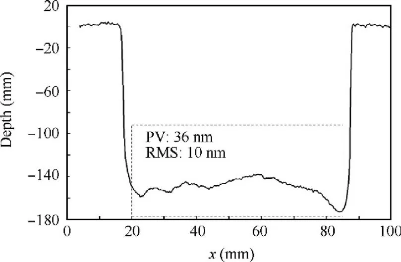
Fig. 7 Mean profile along X direction using ‘‘gully” etched by plasma torch.
5.2. Corrosion on the coil
The plasma figuring process is operated at atmospheric pressure with ambient of air, hence the coil is easily oxidized.The skin depth of this coil is calculated as ~10 μm, and the current will transport just through this thin skin of the coil surface.The coil heats up when ICP torch is powered,thus accelerating oxidation. Various metals can be chosen to fabricate the coil: annealed copper is commonly used as the base material. However, the effect of surface oxidation leads a serious efficiency drop for the plasma ignition and maintenance. The intensity of the EM field is weaker due to the oxidation on the coil,because the copper oxide cannot conduct the alternating current efficiently. Metal plating (silver or gold) could be used, as silver plating enables the best electrical conductivity(6.30×10S/m). Gold plating was not used in this study due to the cost, although it has the best oxidation resistance.Pure silver plating is used for preparing the coil in this investigation, because of the acceptable electrical conductivity of silver oxide (~10S/m). The tarnish should be frequently removed to guarantee the proper performance of coil, and avoid the arcing from the nonuniformed conductivity of the coil due to oxidation.
5.3. Performance of the PDS
This study focuses on the optimization of the parameter settings of the proposed PDS, i.e. recommending the optimum capacitances and induction coil’s geometries. The success of the PDS for future large optical fabrication task is considered in two aspects: first, whether it could provide stable plasma in the long duration; second, whether it could provide deterministic plasma footprint.The tests for obtaining the optimum RF parameters last over 900 min,and the deviation of the RF signal (frequency) is less than 1%. Arguably, the duration test is suggested to be contiguous three hours (estimate duration for one iteration for one metre-size mirror), but the duration in this study is only 30-40 min continuously per test. Therefore,the future work to address this robust PDS will be extending the plasma generating duration for 3 h.For the second aspect,the footprint function has been proven correlated to the processing parameters,e.g.standoff distance,FP,reactive gas species and concentration, etc.The tool function was also tried to be modified through the associated nozzle structures.A digitally supported PDS with multi-sensors will be improved to monitor the plasma etching activities in a safe manner and realize the intelligent control of the plasma footprint in process.
6. Conclusions
This investigation addresses the optimization of the critical parameters enabling a robust PDS.This PDS comprises a fixed match RF network and an ICP torch.Four influencing factors in the PDS are optimized by one-factor-at-a-time method to realise a stable RF signal delivering, easy plasma ignition and a small amount of reflected power. The technical issues are discussed to pursue a stable plasma generation for the industrial demand.The optimum PDS is demonstrated by generating neutral material removal on a fused silica sample. The main conclusions can be drawn as follows:
(1) The tune capacitor has a greater impact than the load capacitor for this PDS radio-frequency network, with evidence of frequency increased by 2% along with the tune capacitance rises by 0.8%.
(2) The coil parameters are critical in influencing the radiofrequency powers. The length of the coil and its free turns should be optimized for effective power transfer from the generator to the ICP torch.
(3) The PDS is tested in a material removal experiment.The 70 mm×200 mm fused silica sample is processed to achieve flatness of 10 nm in RMS within 20 min.
Declaration of Competing Interest
The authors declare that they have no known competing financial interests or personal relationships that could have appeared to influence the work reported in this paper.
Acknowledgement
sThis study was supported by the Engineering and Physical Sciences Research Council (EPSRC) UK (EP/1033491/1), the Science Foundation Ireland (SFI) (15/RP/B3208), and Irish Research Council (CLNE/2018/1530). Finally, our appreciation is given to Cranfield University for the use of their facilities and to their following staff who supported different aspects of this work: Dr Mustapha Gourma and Professor Paul Shore.
 CHINESE JOURNAL OF AERONAUTICS2021年4期
- CHINESE JOURNAL OF AERONAUTICS的其它文章
- Time delay compensation in lateral-directional flight control systems at high angles of attack
- Dual stability enhancement mechanisms of axial-slot casing treatment in a high-speed mixed-flow compressor with various tip clearances
- Development cost prediction of general aviation aircraft using combined estimation technique
- Improvement on shaped-hole film cooling effectiveness by integrating upstream sand-dune-shaped ramps
- Modeling and parameter identification of linear time-varying systems based on adaptive chirplet transform under random excitation
- An experimental method to obtain the hard alpha anomaly distribution for titanium alloy aeroengine disks
