Flow field characteristics, mixing and emissions performance of a lab-scale rich-quench-lean trapped-vortex combustor utilizing a quench orifice plate combined with a bluff-body
Bo JIANG, Gaowei CUI, Yi JIN, Ziqiang ZHAO, Dong LIU,Xiaomin HE,*
KEYWORDS RQL;TVC;Quench orifice plate;Flow field;Mixing level;Emissions performance
Abstract In this study,the low emission combustion technology of Rich-Quench-Lean(RQL)has been applied in Trapped-Vortex Combustor (TVC), and the combinative RQL-TVC shows a promising low emissions performance. By utilizing a quench orifice plate combined with a bluffbody, a lab-scale RQL-TVC was designed. The flow fields of RQL-TVC were measured by 2-D PIV and predicted by 3-D numerical simulation. Flow structures, radial profiles of normalized mean axial velocity,turbulence intensity and mixing level of the quench zone were analyzed.Results reveal that the dual-vortex and the single-vortex flow patterns both exist in cavities and quench zone of RQL-TVC, and the turbulence intensity is strong in the quench zone with some reverse flows.The spiral vortex was discussed by 3-D streamlines and the detail flow structures of the quench zone were analyzed based on the numerical results.The mixing level of the quench zone was determined,and results show that the quench device enhances the mixing level compared with TVC. Combustion efficiency and emissions performance were investigated experimentally, and results demonstrate that RQL-TVC has relatively higher combustion efficiency and lower emission index of CO,UHC and NOx than the same size lab-scale TVC in present work.
1. Introduction
Combustor is one of the key components in a gas turbine engine. In recent years, in order to minimize the formation of pollutants such as nitric oxides (NO), carbon monoxide(CO), and Unburned Hydrocarbons (UHC), significant progresses of the low emission combustion technologies and combustor designs have been made,including some revolutionary design changes for ultraclean emissions performance in the gas turbine combustor.
Hsu has proposed a Trapped-Vortex Combustor (TVC)which employed the cavities instead of the swirlers of a conventional combustor to constrain vortexes to stabilize the flame.TVC shows excellent performance both in combustion and emissions, such as improvements of lean blow-out,altitude re-ignition, operating range, and reduction of NO.Since the end of last century, several generations of TVC have been developed and numerous studies of TVC have been carried out.By using experimental and computational methods, the classical geometry of TVC combustor model has been studied,and the flow fields were also measured using Particle Image Velocimetry(PIV).It is found that a vortex can be trapped stably in the cavity over a wide operating range.The flow fields of TVC with and without bluff-body were compared by Zeng et al.,and the process of forming-breaking down-forming again-being stable for vortexes in TVC was observed. The effect of variety height to length ratios of the cavity on the flow field and Lean Blowout (LBO) of a TVC were studied by Fan et al.Influences of momentum flux ratio on the flow fields and flame structures in the cavity were analyzed using 3-D numerical study under reacting flow conditions by Ezhil-Kumar and Mishra.Impacts of location and angle of primary injection and relative position of the cavityinjector/radial-strut on the cavity flow structure and turbulence intensity distribution in cavities and main zone in TVC were investigated by Jin et al.using PIV measurement,and the interaction between the cavity stream and the mainstream was discussed. Chen and Zhaoadopted a guide vane to guide airflow compulsively into the cavity for the improvement of the vortex structure of the TVC cavity. They studied numerically the effects of the guide vane on reacting flow characteristics in TVC. Recent years, the combustion and emissions performance were wildly investigated using experimental tests and numerical simulations.Flow structures, flow fields and combustion characteristics of the labscale TVC model and the single-cavity TVC were investigated by Jin et al.The effects of strut width, strut length and dome structure on the combustion performance of TVC were also studied experimentally by Wu and Li et al.The combustion,emissions and stability characteristics of dual-channel double-vortex TVC and ultra-compact TVC for gas turbine engines were tested by Zhang et al.Ignition and flow field characteristics of a novel mixed-flow TVC for turboshaft engine were researched by Jiang and He.The above work has greatly promoted the development and application of TVC.
In recent years, low emission combustion technologies for gas turbine engines have been greatly developed,including the Rich-Quench-Lean (RQL). RQL technology is considered as a multi-stage combustion mode and can effectively re-duce emissions.The quick quench stage is one of the vital stages in an RQL mode which includes the stages of rich burn,quick quench and lean burn. The quench zone, which connects the rich zone with the lean zone, is one of the primary regions in a RQL combustor. One of the main challenges in the quench region is to rapidly mix the fresh air into the rich-burnt gas to quickly quench it and then to establish a lean-burn condition. The mixing and subsequent quenching of the rich region products in the quench zone should occur rapidly such that the quenching time scale is very shorter than the kinetic pathways which lead to NOformation as the product mixture transitions across stoichiometry. The design principles for the quench zone of a RQL combustor were reported by Hassa et al.,and RQL’s mixing characteristics under non-reacting conditions were analyzed.The turbulent flow fields of a model RQL gas-turbine combustor were investigated experimentally by Anacleto et al.A Computational Fluid Dynamics(CFD) parametric method was adopted to analyze the mixing performance of crossflow jets with axially opposed rows in a rectangular duct by Bain,and the impacts of lateral geometric arrangement on the mixing performance were discussed.The mixing characteristics between the crossflow jets with perpendicular rows to the mainstream in a rectangular duct under non-reacting conditions were investigated by Liscinsky et al.,and the effects of inlet flow conditions on crossflow jets mixing characteristics were analyzed.
In order to control pollution emissions,the staged combustion mode of RQL has been tried to be applied to TVC.This is a combinative approach to achieve the goal of low emission effectively.Because TVC can be operated as a flexible fuel-supplying combustor, all fuel is injected into the cavity to establish the rich-burn environment. Under RQL mode, the mainstream nozzle and its accessories are abandoned, and the fuel nozzles inside the cavities are replaced with these nozzles with medium mass flow rate,because the previous nozzles for pilot flame are insufficient for the fuel supply of RQL mode. At the same time, the main flow guiding device should be changed to a rapid mixing quenching device for guiding multiple air jets.The air jet flows of mainstream are introduced into the quench zone to quickly mix and quench the burned gas from the rich-burn zone (cavity area). After the progress of rapid mixing and quick quenching, the lean-burn environment is formed. A good combinative Rich-Quench-Lean Trapped-Vortex Combustor (RQL-TVC) design requires not only the formation of stable vortex structures in the cavity to stabilize the flame,but also a double vortex structure to transport and mix the heat and burned gas from the cavity zone into the mainstream flow for providing effective quenching while operating the quench stage in a RQL mode.There-fore, a detailed study on the mixing characteristics of the quick quench stage is of crucial necessity for the RQLTVC design.
In last decades, a significant progress in TVC and/or RQL design has been made severally, and there is some progress in the hybrid approach of RQL-TVC to meet the low emission targets. Agarwal et al.analyzed the complex flow fields in a compact single-cavity RQL-TVC with inclined struts along the guide vane to enhance the mixing.It was found that the interlocked nature of the different flow fields in the spanwise direction was thought to lead to enhanced mixing.Effects on mixing enhancement by two different arrangements utilizing four struts and six struts were compared. In a stationary gas turbine, a main air distributor plate was employed by Straub to quickly mix the burned gas from the cavity with the mainstream flow in a can-type RQL-TVC.The detailed three-dimensional under reacting conditions of a RQL-TVC were used to evaluate the different fuel and air injection configurations by CFD simulation, the effects of cavity residence time and rich-zone equivalence ratio on the potential high temperature regions were analyzed. Unfortunately, the flow field and the mixing characteristics of the can-type RQL-TVC were not given in detail.In our precious work,flow structures of the quench zone in a RQL-TVC model were investigated by computational study,and the effects of multi-orifice configurations in a quench plate on mixing characteristics of the quench zone were discussed experimentally.
The design principles and research of performance optimizations for RQL, TVC models in gas turbine engine have been extensively carried out individually, but little analysis of detailed flow field characteristics in a hybrid RQL-TVC is available, especially for the quench zone which is the most important transition stage for minimizing NOx emissions in a hybrid RQL-TVC. This paper will focus on a combinative approach in which the TVC was operated as an RQL mode.A rectangular lab-scale RQL-TVC was designed by utilizing an orifice plate quench device combined with a bluff-body to enhance the mixing performance in the quench zone.PIV measurements and numerical studies were carried out in this work to investigate flow fields and mixing characteristics of the cavity and the quench zone in RQL-TVC. The emissions performance was investigated and discussed by combustion experimental tests on the same size lab-scale RQL-TVC.
2. RQL-TVC model, experiment setup, computational domain and numerical method
2.1. RQL-TVC model
Fig. 1 shows a 2-D schematic and a 3-D model of the RQLTVC utilizing the quench orifice plate combined with a bluffbody. The RQL-TVC model is generally a 180 mm-wide rectangular combustor. It contains the components including a diffuser, two cowls, a quench device in the mainstream area,cavities,liners and casings.In Fig.1,H is radial length of cavity, mm, L is axial length of cavity, mm. As shown in Fig. 2,the air is introduced into the diffuser, and then divided into three streams by two cowls. Some of the air is introduced through the orifice plate to quench the burned air/fuel from the cavities, and some of them are introduced into the cavities to be trapped as the vortexes through the slots located in the fore-wall and the aft-wall of the cavities, as fore-slot and aftslot, respectively. The others are introduced into the cooling holes.In Fig.2,R is the radius of the orifices in the quench orifice plate, land lare the half width of the radial-strut, and l=l. lis the width of the mainstream area, his the height of the mainstream area,his the half height of the bluff-body.
The RQL-TVC model is combined a typical TVC with a quench device to connect the rich burn with the lean burn in order to perform the staged combustion as a low emission combustion technology of RQL. Typical RQL combustion mode it that whole fuel is sprayed into the cavity of RQLTVC to mix with air and burn under rich-burn condition.Subsequently, the burned gas flows to the quench zone to mix fast with the air mainstream to be quenched quickly and cool down. Then, the quenched mixture continues to burn completely under lean-burn condition. Rapid mixing and quenching are the key to the connection between richburn and lean-burn in RQL model. How to achieve effective and fast mixing and quenching is crucial for RQL-TVC design. The purpose of the fast mixing is to achieve a quick quenching effect between the burned gas from the cavity and the fresh air mainstream. This purpose need to design a specific structure to achieve. In this work, a quench device with combination of orifices, the radial-strut and the guiding bluff-body was de-signed as shown in Fig. 3(a). It is optimized from a mainstream guiding device in TVC as shown in Fig. 3(c). Figs. 3(b) and (d) show the comparison of 2-D schematic between the RQL-TVC quench orifices and the TVC mainstream. The quench orifices are designed as triangular and circular orifices in order to increase the con-tact proportion for the mixing and quenching of the cross flows.The principle of the quench device design is that the contact area between the air mainstream jet and the burned gas from the cavity is obviously increased, which is conducive to the rapid mixing of the two flows, but the blocking ratio remains the same level approximate-ly. This means that the flow rate and the velocity of the air mainstream are not changed. If the blocking ratio changes too much, it may lead an obvious change of the flow distribution of flow paths in the combustion chamber, which further leads to the changes of the flow field and the combustion performance.
The triangle orifices and the circular orifices were employed in the quench device as shown in Fig.3(a)and(b).The triangle orifices can introduce the air mainstream as wedge jet flow into the quench zone located the downstream direction. The tip of the wedge jets meets the burned gas coming from the cavity.This arrangement is beneficial to increase the contact area of the two flows and enhance the mixing effect. The circular jets introduced by the circular orifices is located at the rear of the wedge jet can form a stirring effect. This further increases the mixing effect of part of the burned gas after bypassing the wedge jet. As shown in Figs. 3(b) and (d), the total area of RQL-TVC quench orifices is 94% of that of the rectangular holes in the TVC mainstream area, but the total length of the perimeter of RQL-TVC quench orifices becomes 2.2 times of that of the rectangular holes in the TVC mainstream area.This means that the jet velocity would increase slightly due to the slight increase of the blockage ratio.This design has little impact on the flow distribution, while the mixing area has been enhanced to 2.2 times which indicates that RQL-TVC quench orifices could offer obvious enhancement of the contact proportion in the same flow area.Obviously,this strategy could be beneficial to improve the mixing effect in the quench zone of RQL-TVC, and further to promote its quenching performance.

Fig. 1 2-D schematic and 3-D model of RQL-TVC.
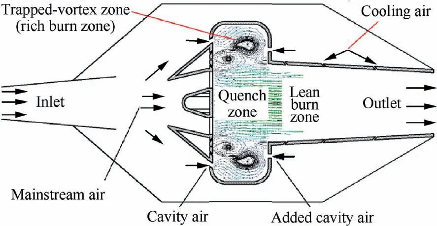
Fig. 2 2-D schematic of air flowing routes in RQL-TVC.
2.2. PIV experimental setup
The PIV test rig is comprised of a stainless steel combustor frame fitted with plexiglass and silica glass walls to permit high quality optical access for the PIV measurements, as shown in Fig. 4. The experimental setup of PIV test system is schematically shown in Fig. 5. The PIV tests were performed at atmospheric pressure and room temperature. The airflow rate was metered and adjusted by controlling an orifice plate flowmeter and a butterfly valve.
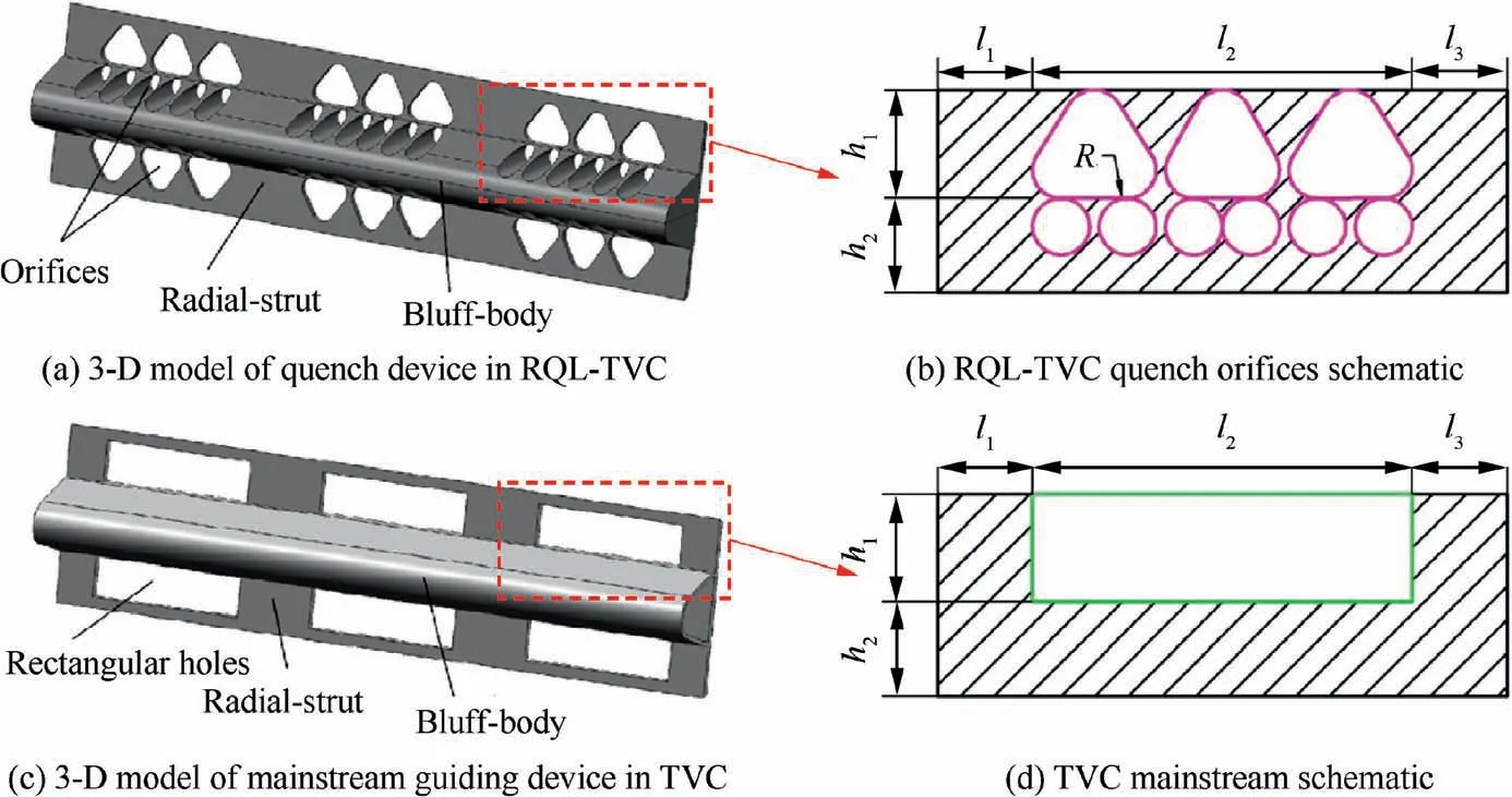
Fig. 3 Comparison of 3-D model and 2-D schematic of RQL-TVC quench device and TVC mainstream guiding device.
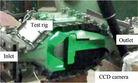
Fig. 4 Photograph of PIV test rig.
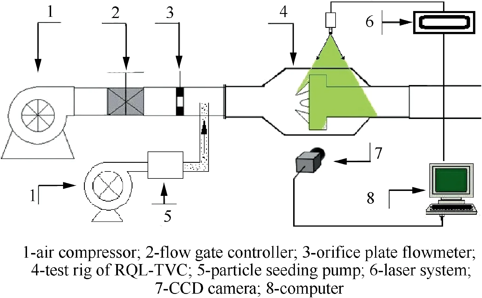
Fig. 5 Schematic of test setup of PIV test system.
The PIV system includes a 2048×2048 pixel chargecoupled device (CCD) camera (LaVision Imager ProX 2 M)and a 200 mJ per pulse of double pulsed Nd:YAG laser that is synchronized with the CCD camera. The time separation between the two laser pulses is set to 20 μs for the flow conditions studied.The laser light sheet is projected perpendicularly to z-axis,and the recording CCD camera is directed normal to the x-y plane, as shown in Fig. 1 and Fig. 5. Solid tracer particles of nominal diameter of 5 μm were introduced into the air flow 1000 mm upstream of RQL-TVC inlet using a simple fluidized bed particle dispenser.Image mapping,calibration,and particle cross-correlations were completed using the commercial software of La Vision DaVis 7.2. 200 images are used to calculate the time average velocity. The estimated uncertainty is about 9% in the wake region near the wall, and the overall uncertainty is 2% in the main regions.
In this work,the talc powder was selected as the tracer particle for PIV measurement. The size of the talc powder was 2500 mesh,its particle diameter was about 5 um.The distance between the placement position of tracer particles and the inlet of RQL-TVC combustion chamber model was 1 m.The tracer particle supply system is shown in Fig.5.The talc powder was fed into particle seeding pump to mix with the compressed air,and then the mixture sprayed into the main air flow through a spray rod placed in the test pipe. In the experiment, the tracer particle was well followed with the main air flow and the measured results were reliable.
2.3. Combustion experimental setup
As shown in Fig.6(a),the combustion experimental test model of RQL-TVC has the same size of its PIV test model.The combustion test rig is made of 310S stain-less steel to provide good durability, as shown in Fig. 6(a). On one of the lateral sides,the 15 mm thick silica glasses are installed to offer the flame visualization.A spark plug mounted on one side of the bottom walls of the cavities is used as the ignition source. The liner walls downstream of cavities are cooled by the air film to prevent burnt by the high temperature flame, while the walls of the cavities and rich burn zone are without air film cooling.It is because that the temperature is not too high in rich burn condition. Furthermore, the main reason is that a large stoichiometric interface will be created in case that the fresh air film cooling air touches the rich fuel/air mixture. According to the mechanism of NOformation, this phenomenon will lead to a sharp increase of the emission level of NO.
In order to compare the emissions performance between RQL-TVC and TVC, combustion tests were investigated respectively by operating different fuel arrangements. In RQL-TVC, all jet fuel RP3 is delivered to the trapped-vortex zone / rich burn zone through fuel nozzles. Six nozzles of Pressure-Swirl Injectors(PSIs)marked as PSI1(3 for each cavity) located in the fore-slot were employed, as shown in Fig. 6(b). In the general TVC, some fuel is delivered into the trapped-vortex zone for the pilot flame by six nozzles of PSI2(3 for each cavity),and the dominant fuel is delivered into the mainstream by three nozzles of PSI3. These three types of nozzles have different fuel mass flow rate,fuel supply pressure and Surface Mean Diameter (SMD) as shown in Fig. 7.
The experimental setup is schematically shown in Fig. 8.Dry air from the compressor is preheated to 473 K by a 250 kW electrical heater and supplied to the combustor. Airflow rate is controlled by a butterfly valve and metered by an orifice plate flow meter. The fuel flow is regulated with a turbine meter.The uncertainties in the air flow and fuel flow measurements are both 1%.
Gas sample collecting and analysis system is depicted schematically in Fig. 9.Combustor exhaust gas is collected and linked to gas analyzers through electric heated tubes.The sample gas is kept about 160℃along the line for UHC measurement, and 65℃for the other gas species. Two SIEMENS ULTRAMAT 23 gas analyzers were employed for CO, CO, NO, CHand Omeasurements. A SIEMENS FIDAMAT 6 gas analyzer is utilized for UHC concentration measuring. The UHC measuring principle is based on the Flame Ionization Detection (FID) with a minimum detection level of about 0.1 ppm.For all the composition measurements,system errors are about 1%.
The combustion experiment is conducted at the atmospheric pressure. Combustor inlet temperature T and inlet Mach number Ma are kept constant as 473 K and 0.25,respectively. In this work, we aim to compare the mixing and emission performance between RQL-TVC and TVC under a typical operating condition. Under the condition of T=473 K and Ma=0.25, a certain temperature rise of 473 K at the inlet of the combustor is conducive to the liquid fuel atomization and ignition of the fuel-air mixture, which can ensure a more stable combustion state. The airflow velocity of Ma=0.25 is a typical value of the inlet velocity range at the inlet of the combustor, which enables the airflow to have enough kinetic energy to flow through the combustion chamber to form a vortex to stabilize the flame,and helps to mixing between the fuel particles and the air.CO,UHC and NOvolume fractions in the combustor exhaust gas are measured under various equivalence ratios in cavities and/or mainstream. These operating parameters are shown in Table 1. In RQL-TVC, the mainstream has no fuel supply under RQL mode, all fuel is only injected into the cavities. The local fuel/air environment in the cavity is defined as the rich burn equivalence ratio Φ. Including all air introduced for mainstream, cavities and cooling, the globe fuel/air environment of RQL-TVC is defined as the global equivalence ratio Φ.In this RQL-TVC, since the flow distribution of the cavity is 28% of the combustor total gas flow, there is a relationship as Φ=28% Φbetween the global equivalence ratio and the rich burn equivalence ratio. In TVC, the fuel supply both in the mainstream and the cavities. Some fuel is injected into the trapped-vortex zone to establish the pilot flames. The equivalence ratio of fuel/air environment of the pilot flame is defined as Φwhich is kept constantly as 0.667.The dominant fuel is injected into the mainstream using nozzles with relatively large mass flow rate. In general, TVC also has a global equivalence ratio Φ, which includes all introduced air.
2.4. Computational domain and numerical method
In order to understand the detail flow field of three dimensionalities,to explain the 3-D vortex features in RQL-TVC,and to determine the mixing level of quench, it is necessary and of crucial importance to find out the flow field on the other monitoring planes perpendicular to x-axis and y-axis. The advantage of CFD method could be utilized to accomplish the numerical simulation study, and commercial CFD software FLUENT is employed.

Fig. 6 Combustion test rig of RQL-TVC and fuel arrangement.
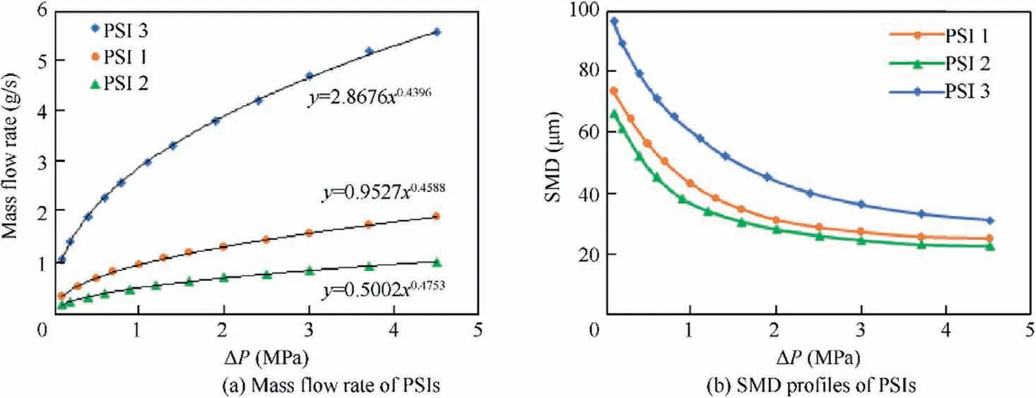
Fig. 7 Mass flow rate and SMD with fuel supply pressure of PSIs.
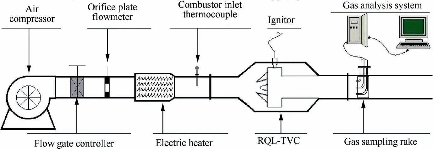
Fig. 8 Schematic of test system.
The configuration of the liner in RQL-TVC is shown in Fig. 10(a). The height of the liner is H=54 mm, and the height of the cavity is H/2. The width of the cavity is L=38 mm, and the total spanwise length is 60 mm. Because of symmetry feature, half of the spanwise length, as N=30 mm, is chosen to show the monitoring planes. X, Y,Zare the coordinate values of the chosen ordinal points on L, H, N, respectively. Measurements are conducted in three spanwise monitoring planes perpendicular to z-axis, as Z/N=0, 0.5, 1, shown in Fig. 10(b). The first plane,Z/N=0,is located at middle position of the two radial struts on the quench side, the second plane, Z/N=1, is along with the central line of the radial strut, and the third plane,Z/N=0.5, is located in the middle of the first plane and the second plane. In present experimental work, the PIV measurements are only performed on the monitoring planes of Z/N=0, 0.5, 1, perpendicular to z-axis as shown in Fig. 10(b).
The boundary conditions in the numerical study are shown in Fig. 11. The computational domain corresponds to one sixths of the PIV test rig with translational periodicity on the two lateral sides. Rectangular lab-scale RQL-TVC is an axisymmetric component, so the symmetric surface of the RQL-TVC model is set as the boundary condition of the symmetry. The boundary conditions of mass-flow-inlet and pressure-outlet are employed at the inlet and the outlet,respectively. The other boundary surfaces are set as the wall boundary conditions. To simulate non-reacting flow field of RQL-TVC, the steady-state continuity and momentum equations are discretized with a finite volume method. Convection and diffusion terms are discretized by the second-order upwind scheme.The SIMPLE algorithm is applied for pressure-velocity coupling, and the standard wall functions are utilized to conduct the near-wall region.
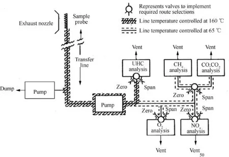
Fig. 9 Schematic of gas sample collecting and analyzing system50.

Table 1 Operating parameters.
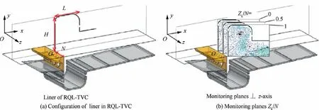
Fig. 10 Schematic of the monitoring planes of Zk/N for PIV measurements.

Fig. 11 3-D view of the grid determined by grid independent study.
By performing a grid independency study on five different grids, the solution was ensured to be independent from the grid.The details of the five grids are given in Table 2.By monitoring radial profiles of the mean axial velocity and radial velocity on the intersection lines of X/L=0.2, 0.6, 1 shown in Figs. 12(b) and (c) with Z/N=0, 0.5, 1, respectively. Itis observed that there is approximately little difference among the profiles predicted by G3,G4 and G5,therefore,the grid G4 was adopted for the present numerical simulation work. 3-D view of the grid determined by grid independent study is shown in Fig. 11. The monitoring planes of X/L=0.1-0.9 and Y/H=0.09, 0.19, 0.28, 0.37, 0.46 as shown in Figs. 12(a) and (b) are employed in the numerical study. The relative positions of monitoring planes of X/L and Y/H are shown in Fig. 12(c).

Table 2 Details of five grids used for grid independency study.
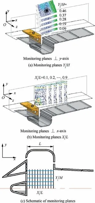
Fig. 12 Schematic of monitoring planes of Xi/L and Yj/H for numerical study.
The steady Reynolds-Averaged Navier-Stokes (RANS)approach is employed. The comparative study of the turbulence model is performed under the RQL-TVC case with reference to the literature, the standard k-ε model was adopted as the turbulence mode.The turbulence model is determined by comparing the global flow structures of experimental and computational results which are predicted by the standard kε model, the realizable k-ε model, the RNG k-ε model and the SST k-ω model respectively, as shown in Fig. 13 on Z/N=0. It can be clearly seen from the flow filed patterns, the predicted result of the standard k-ε model is better to agree with the test result of the PIV measurement, and other three models fail to capture the primary flow features of the present RQL-TVC. The models Realizable k-ε and RNG k-ε both fail to accurately predict the direction of the jet from the fore-slot,thus the predicted flow fields are also wrong.The models RNG k-ε and SST k-ω both overestimate the size and distribution of vortexes in the cavities, so the predicted flow fields are quite different from the measured result of PIV.Therefore,the standard k-ε model was adopted as the turbulence model.
3. Results and discussions
3.1. Flow fields analysis
3.1.1. Flow fields analysis by PIV measurements
Under atmospheric pressure and room temperature, PIV experiments were conducted to find out the mean flow fields of RQL-TVC. Fig. 14 shows the streamlines overlaid on the vector patterns of velocity on Z/N=0, 0.5, 1 at Ma=0.25. As showed in Fig. 14(a), it is clear that the dualvortex airflow structures are established in the cavity on Z/N=0, and the single-vortex is located in the cavity Z/N=1. Additionally, the flow field shows the transition pattern of airflow structure between the dual-vortex and the single-vortex on Z/N=0.5. Fig. 14(b) shows the details of the flow fields in the quench zone of RQL-TVC.
The dual-vortex, shown on the plane of Z/N=0 in Fig. 14(a), is established in cavity by the interactions of three streams of airflows. Two streams are introduced from the fore-slot and the aft-slot, respectively, and the third stream is injected from the quench orifice located at the mainstream area as the fresh quench airflow. The dual-vortex is trapped by the effects of the third stream as shown clearly in plane Z/N=0 of Fig. 14. The bigger vortex of the dual-vortex is helpful to stabilize the flame in the cavity and complete the rich burn stage in RQL mode. The smaller vortex of the dual-vortex is beneficial to transfer the burnt gas and heat from the cavity to the mainstream and mix with the fresh quench air. On the plane of Z/N=1 in Fig.14(a),a large-scale single-vortex fills the cavity by the effect of the radial-strut without the quench airflow. As shown in the quench zone of Z/N=1 in Fig.14(b),the airflow of the single-vortex travels to the downstream region of the radial-strut and the bluff-body, an additional vortex is established in the downstream position. On the one hand, the single-vortex transmits the burnt gas and heat to the center of the mainstream for mixing, and on the other hand, it transmits the flame to mix and ignite the quenched gas after the quench stage. The transition patterns of airflow structure between the dual-vortex and the singlevortex are shown on the plane of Z/N=0.5 in Fig. 14(a).It can be seen from the flow fields of the quench zone in Z/N=0.5 in Fig. 14(b) that the streamlines touch with each other, and the airflow from the cavity mixes with the quench flow from the quench orifices.

Fig. 13 PIV measured and computational streamlines of deferent turbulence model in Zk/N=0 at Ma=0.25.
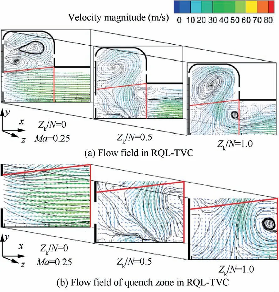
Fig. 14 Streamlines overlaid on vector patterns of velocity in monitoring planes ⊥z-axis,showing the vortical flow structure at Ma=0.25.
In order to further understand detail features of flow fields in the cavity and the quench zone of RQL-TVC,radial profiles of normalized mean axial velocity (V/V), normalized mean radial velocity (V/V), and the turbulence intensity were determined as shown in Fig.15 and Fig.16,respectively.There is a dotted blue line in each figure to represent the boundary between the cavity zone and the mainstream zone.
Radial profiles of V/Vand V/Von the intersection lines of the planes of X/L and Z/N at Ma=0.25 are shown in Fig.15.The mean values of the two velocity components,as V, V, have been normalized by inlet velocity Vdefined as,V=W/(ρA ) (1)where Wis the measured inlet air mass flow rate,A is the inlet area of RQL-TVC, and ρ is the density of inlet air. Under the dotted line in each figure, it shows the radial profiles of monitoring lines in the quench zone. On the contrary, they are the profiles in the cavity above the dotted line. It can be seen in Fig. 15(a) that V/Vincreases with the increasing of X/L firstly,and then reaches the highest values,while V/Valmost keeps stable around 0 as shown in Fig. 15(b). As shown in Figs. 15(c) and (e), the radial profiles of /Vgive very similar trends and keep the values of V/Vto closed 0 in the quench zone, except the downstream position in Fig. 15(e). But in Figs. 15(d) and (f), the radial profiles of V/Vshow different trends in the quench zone,and the values of V/Vare almost negative. It means that the airflow with diverse radial velocity Vtransfers from the cavity to the quench zone, and then it mixes with the quench airflow jets from the quench orifices.
In Fig. 16,the radial profiles of turbulence intensity on the intersection lines of the planes of X/L and Z/N at =0.25 are determined. The turbulence intensity is defined as:V

where V’is the rms fluctuation of V,and V’is the rms fluctuation of V.
As shown in Fig. 16(a), it can be clearly seen that the turbulence intensities are very strong above the dotted line in the cavity,and they keep the same week level under the dotted line in the quench zone.But the opposite features of the radial profiles of turbulence intensity are revealed in Figs. 16(b) and(c). They demonstrate that the levels of turbulence intensity,between 50%and 400%,are very strong under the dotted line in the quench zone.The diverse trends and levels of turbulence intensity under the dotted line show that strong mixing among the cross flows from the cavity and the quench orifices are occurred. This phenomenon is conducive to enhance the mixing proportion in the quench zone. It is believed that the enhancement of mixing in the quench zone may contribute to a better quenching functionality of RQL quench stage which is a key point for the RQL combustion technology.
3.1.2. Flow fields analysis by numerical simulation
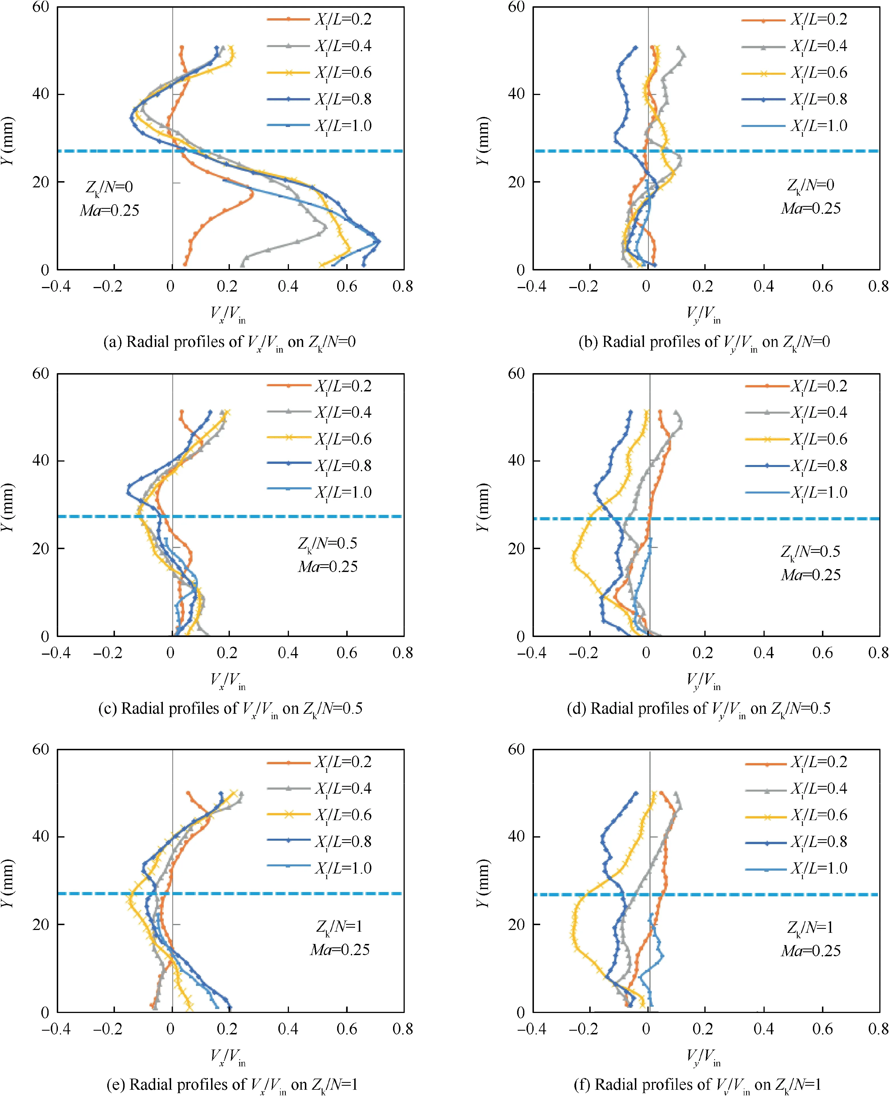
Fig.15 Radial profiles of the normalized mean axial velocity(Vx/Vin)and radial velocity(Vy/Vin)on the intersection lines of the planes of Xi/L and Zk/N at Ma=0.25.
More detailed comparisons of the velocity distributions of vortex structure between PIV measurements and the predicted results of the numerical study in the present RQL-TVC are shown in Fig. 17 on representative plane of Z/N=0 at Ma=0.25.It is found that the predicted vortex core locations in the radial direction are in very good agreement with that of PIV measured results. The radial profiles of the axial velocity on the lines of interactions of planes of X/L and Z/N=0 are compared to the PIV experimental results in Fig. 18. It is evident that the change trends of the radial profiles of the velocity components,as Vand V,are in the consentaneous agreement to corresponding ones for the results of PIV measurements and CFD predicted.It demonstrates that the computational results reproduce the flow feature qualitatively and quantitatively.Therefore, it is valid to utilize the present numerical method to predict the detail flow fields of the RQL-TVC.
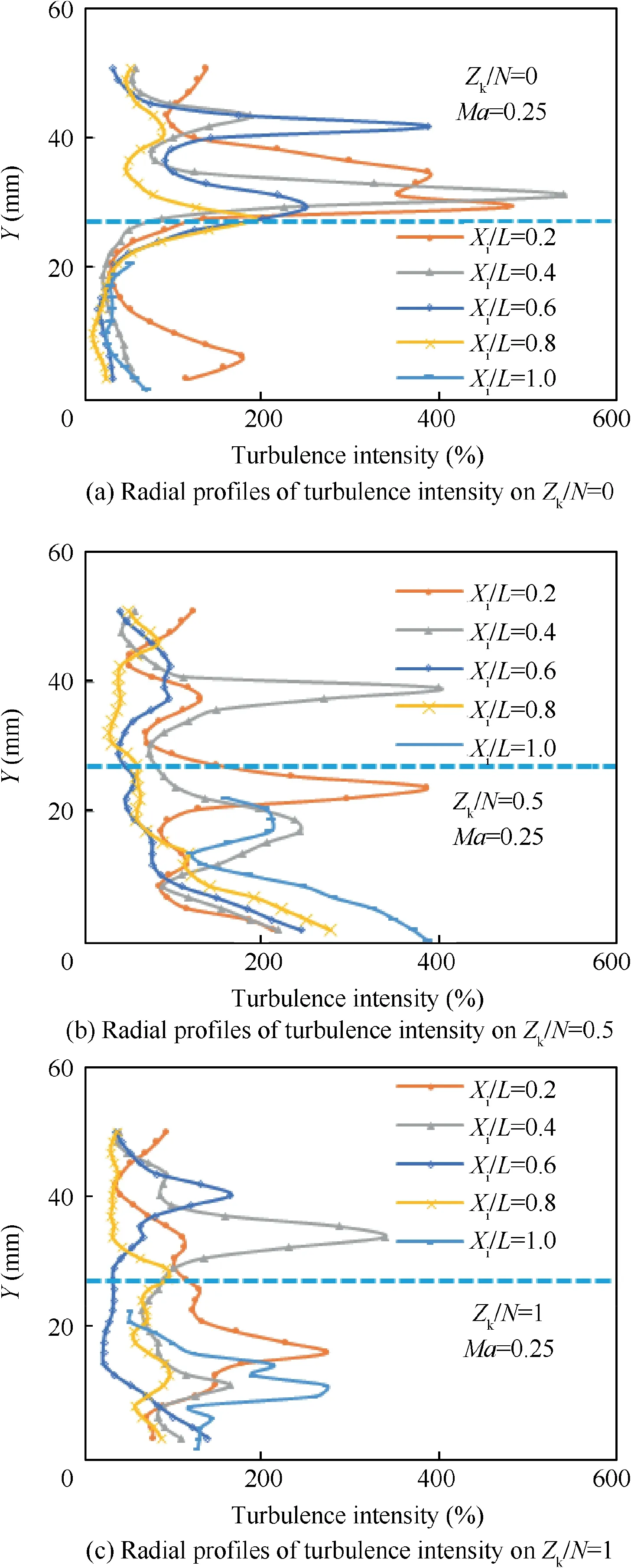
Fig.16 Radial profiles of turbulence intensity on the intersection lines of the planes of Xi/L and Zk/N at Ma=0.25.
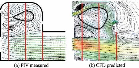
Fig. 17 Comparison of PIV measured and CFD predicted flow structures in Zk/N=0 at Ma=0.25.
Fig. 19 displays the 3-D streamlines predicted by CFD to show the spiral vortical flow structure of RQL-TVC. Fig. 19(a1),(a2)and(a3)gives the 3-D streamlines which is originated from the fore-slot on Z Z/N=0. Firstly, it travels as a lager vortex of the dual-vortex.Secondly,it spirals toward the plane of Z/N=1.Thirdly,it travels back to the plane of Z/N=0 as a smaller vortex of the dual-vortex, as well as it mixes with the quench airflow and follows it toward the downstream direction. The 3-D streamlines which is originated from the fore-slot on Z/N=0.5 are displayed on Fig.19(b1),(b2)and(b3). It directly spirals toward the plane of Z/N=1 and follows the single-vortex behind the radial-strut to travel toward the bluff-body, then it is in the same way to mix with the quench airflow toward the downstream direction. By combining the information of flow fields from Fig. 14 and the 3-D streamlines from Fig. 19, the spiral vortex transits the airflow from the cavity along the radial-strut to the bluff-body, and it is beneficial to the mixing of cross airflows and the dual-vortex transitions.It may be concluded that the transition and exchange of the mass and the momentum are always occurred between the dual-vortex and the single-vortex. Therefore, the spatial dual-vortex could not only stabilize the flame for rich burn stage in the cavity, but also transmit the burnt gas and heat from the cavity to the mainstream for mixing and quenching.It can be found that the vortexes in RQL-TVC are the 3-D vortexes with the spatial characteristics as shown in Fig. 19,and the 2-D dual-vortex or the 2-D single-vortex in Fig. 14 are the local representation of flow structures of the split 3-D vortexes
In order to determine the detail flow structures of the quench zone, the 3-D quench space is split as the monitoring planes,and the positions are shown in Fig.12.The monitoring plane series of Y/H and X/L are perpendicular to x-axis and y-axis,respectively.The streamlines overlaid on the vector patterns of velocity are shown in Fig.20 on monitoring plane series of Y/H and X/L, respectively, at Ma=0.25.
Fig. 20(a) shows that the evident changes of the vortexes are occurred on the planes of Y/H. On the five planes of Y/H from 0.09 to 0.46, a stable vortex with the clockwise direction is established and grows gradually behind the radialstrut. It is obviously interacted by the quench airflow and the airflow which is from the cavity and travels along the radial-strut to the bluff-body. This clockwise vortex is disappeared on Y/H=0.46. Due to the effect of the small vortex of the dual-vortex, flows with the opposite direction to the downstream are formed.
It can be seen from Fig.20(b)that various vortexes exist in the downstream position of the quench airflow on monitoring planes as X/L from 0.1 to 0.9. These vortexes are constantly evolving with the changing of plane locations. As shown on the plane of X/L=0.1,the small vortexes are located between the triangular and circular quench airflows.Some airflow from the cavity goes through the clearances of triangular quench airflow and the others come to mix the quench airflow from the locations behind the radial-strut and the bluff-body. On the planes of X/L from 0.2 to 0.9, vortexes are located between the triangular and circular quench airflows as well as the mixing process is advancing following the changing of the downstream positions. This suggests that the mixing is occurring in the quench zone of RQL-TVC.
On the monitoring planes of X/L in quench zone,the mean vorticity which dedicates to the mixing effect is shown in Fig. 21. It is clearly seen that the mean vorticity of |ω|of y-axis is much higher than |ω|of x-axis in range of X/L=0.1-0.8.It means that the|ω|offers the most contribution to the mixing effect of the quench zone. |ω|deceases monotonically from 11500(1/s) to 1500(1/s) and meets |ω|at X/L=0.9 and 1. |ω|varies non-monotonicially and keep around 2000(1/s) except the one of the X/L=0.1 as 4600(1/s) approximately.
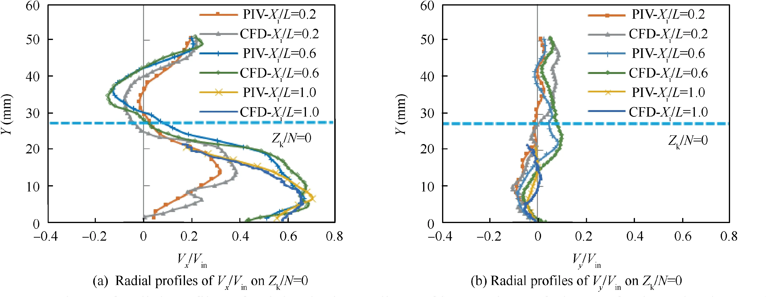
Fig.18 Comparison of radial profiles of axial velocity on lines of interactions of planes of Xi/L and Zk/N=0(PIV measured and CFD predicted).
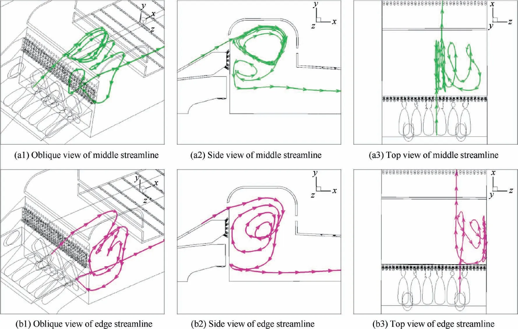
Fig. 19 3-D streamlines in RQL-TVC predicted by CFD with standard k-ε turbulence model, showing spiral vortical flow structure at Ma=0.25.
3.2. Mixing determination
In a two-stream mixing problem,the fully mixed concentration is defined by the jet-to-mainstream mass flow ratio.A measure of the mixing rate can be obtained by comparing the jet or the mainstream mixture fraction distribution at any downstream plane to the fully mixed value. There is a measure of the unmixedness based on the variance of concentration distribution, defined as the spatial unmixedness rate U:


where Cis defined as the concentration at a cell, the cells’patterns as shown in Fig.22,Cis defined as the average concentration of the cells in one of the monitoring planes of X/L as shown in Fig.12,Cis defined as the variance of the fully mixed concentration.The mand nare the number of the horizontal and vertical cells of each monitoring plane of X/L in the quench zone as shown in Fig.22.If U=0,it corresponds to a perfectly mixed system.
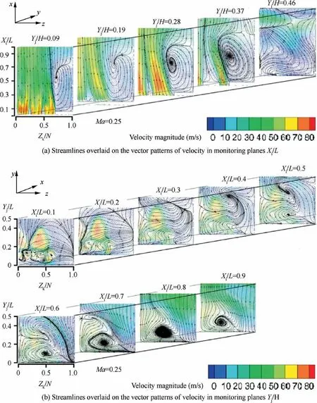
Fig. 20 Streamlines overlaid on vector patterns of velocity in monitoring planes of Xi/L and Yj/H, showing vortical flow structure at Ma=0.25.
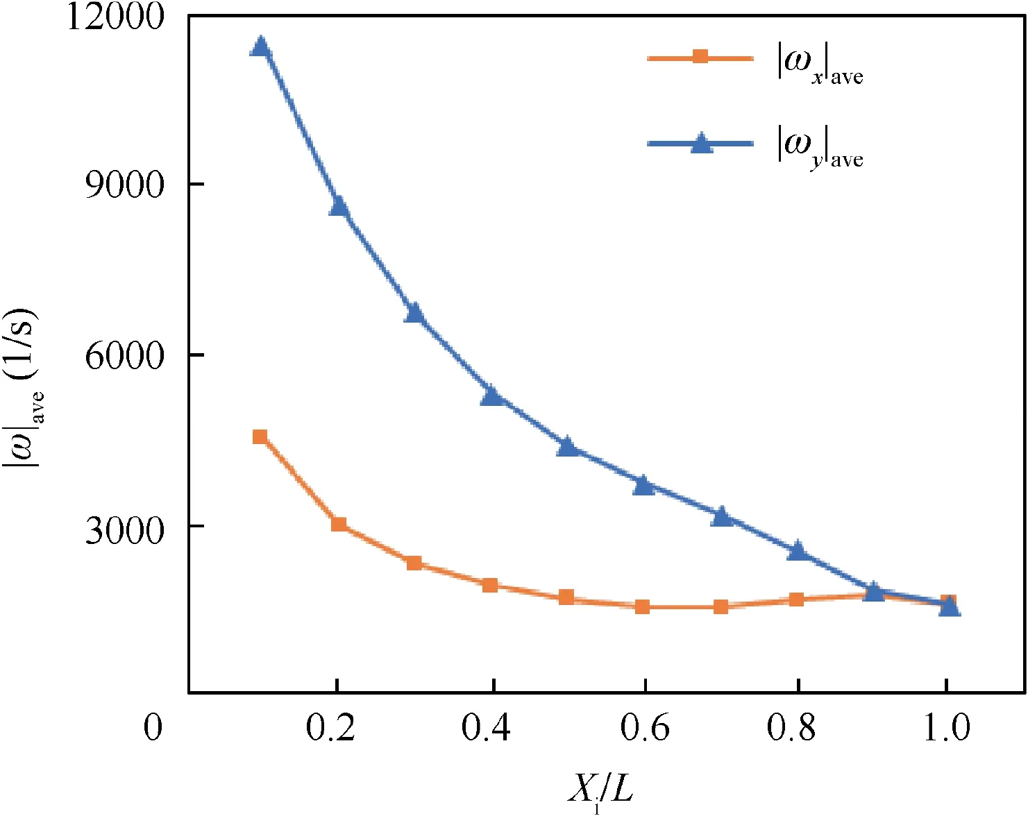
Fig. 21 Mean vorticity on monitoring planes of Xi/L in quench zone.
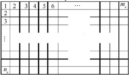
Fig. 22 Cells in each monitoring plane of Xi/L in quench zone.
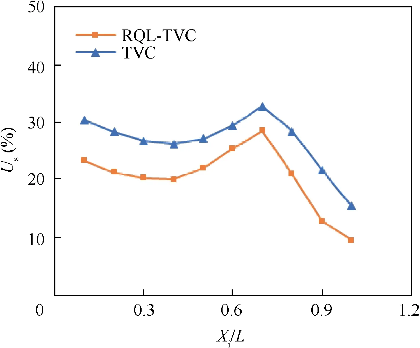
Fig. 23 Unmixedness profile of quench zone in RQL-TVC compared with that in TVC at Ma=0.25.
The mixing levels of the monitoring planes of X/L in the quench zone of RQL-TVC are determined from the numerical results. In order to compare the mixing levels between RQLTVC and TVC, the unmixedness of TVC is also investigated.The profiles of the unmixedness rates are plotted in Fig. 23.It reveals that the unmixedness rates of RQL-TVC are lower than that of TVC on all of the monitoring planes of X/L.This indicates that the quench device offers a significant mixing effect to the quench stage of RQL-TVC.Otherwise,the trends of the unmixedness rates of RQL-TVC and TVC are very similar. The profiles of unmixedness rates of both RQL-TVC and TVC are non-monotonicially. Firstly, the unmixedness rate decreases smoothly as well as the quench airflow is injected to mix with the flow from the cavity to become as the preliminary quenched airflow. Secondly, the unmixedness rate increases and peaks at the region of X/L=0.7. According the flow fields in Fig.14,it can be found that the added airflow is injected form the aft-slot to join the aforementioned preliminary quenched airflow suddenly and enhances the local unmixedness rate.After that,multiple flows including the fresh airflow jets from the quench orifices and two flows from the cavity are mixed together to become a more homogeneous mixture in the end of quench zone as well as a lean condition for the lean stage of RQL is established.Finally,the unmixedness rate decreases rapidly to a low level as the final quench mixing level 9.5%and 15.4%for RQL-TVC and TVC,respectively.Due to the effect of the quench device,the unmixedness rate of RQL-TVC is reduced by 38.3% than that of TVC.
3.3. Emissions performance
In order to verify the role of quench device in reductions of pollutant emissions, the combustion experimental tests of RQL-TVC and TVC were carried out, the combustion efficiency and emissions performance were obtained.
Combustion efficiency η is calculated using the following expression:

where[]denotes volume concentration of each component in the combustor exhaust gas.
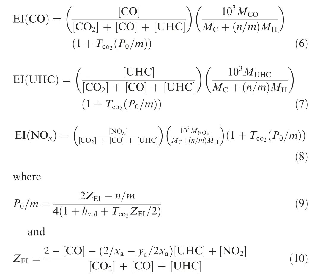
According to International Civil Aviation Organization(ICAO) standard,concentrations of CO, UHC and NOin the exhaust gas are converted to Emission Index(EI).The relations are shown as following,where M is molecular mass of one component in the combustor exhaust gas,Tis concentration of COin dry air,by volume=0.0003 normally,Pis number of moles of air per mole of fuel in initial air/fuel mixture, m is number of C atoms in characteristic fuel molecule,n is number of H atoms in characteristic fuel molecule,his humidity of ambient air,vol water/vol dry air, xis number of C atoms in characteristic exhaust hydrocarbon molecule, yis number of H atoms in characteristic exhaust hydrocarbon molecule.
The comparison of combustion efficiency and emissions performance between RQL-TVC and TVC are shown in Fig.24.Because all fuel is injected in to cavities to create a rich burn zone and then this rich condition transfers to a lean burn condition by the quenching effect of the added fresh air, there is a function between the equivalence ratio in rich zone Φ(only for RQL-TVC) and the global equivalence ratio Φin RQL-TVC. Since the flow distribution of the cavity is 28%of the total gas in this RQL-TVC, the function is Φ=28%Φ. They are marked on the top and the bottle abscissa,respectively. But Φdoes not apply to the fuel-air condition of TVC. Because Φ=0.38 is the smallest of TVC equivalence ratio in this study. Fuel is fed into both the mainstream and the cavity in TVC. The cavity is used to provide a pilot flame and its fuel supply is constant. When the mainstream has no fuel supply, only cavity has been fed the constant fuel,now TVC has the smallest equivalence ratio of Φ=0.38. So the data for Φ<0.38 does not exist for TVC in this study.When the fuel of mainstream is supplied and the flow rate of fuel continues to increase, the TVC equivalence ratio also increases. However, in RQL-TVC, all fuel is only supplied in the cavity, and the flow rate of fuel can reach a smaller value,so the equivalence ratio of RQL-TVC can be continuously decrease less than 0.38.
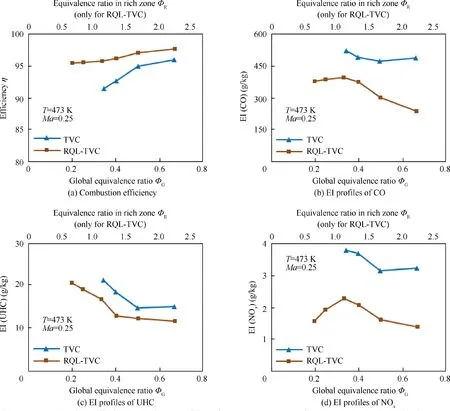
Fig. 24 Combustion efficiency and EI profiles of NOx, UHC, CO of RQL-TVC compared with TVC.
Fig. 24(a) depicts that the combustion efficiency increases as well as the rise of equivalence ratio.Because the combustion tests are performed in combustors with the same size, the residence times in RQL-TVC and TVC are approximately the same level. Here, the fuel atomization particle size becomes the key elements for combustion performance. Under higher equivalence ratio, the injectors with higher fuel pressure could produce smaller fuel particle size to be of benefit to the combustion efficiency. It is notable that the level of combustion efficiency in RQL-TVC is relatively higher than that in TVC under the same global equivalence ratio. Because of the dominant fuel delivered to the mainstream in TVC, the fuel supply in the mainstream generally chooses the fuel nozzles of PSI3 with a large mass flow rate. If Φis very small at the beginning of the fuel supply, the flow rate of fuel is also very small.It means that the fuel supply pressure of the nozzle is very low.According to the general characteristics of the nozzle,when the fuel supply pressure of the nozzle is very low, its fuel atomization quality is worse,and the fuel particles are relatively larger as shown in Fig. 7, resulting in insufficient combustion and relatively low combustion efficiency. With the increase of the fuel flow rate and the fuel supply pressure of the nozzle in the mainstream of TVC, the fuel atomization quality is improved and the fuel particles become smaller based on the SMD profiles of PSIs in Fig. 7. This leads the combustion condition becomes better,and the combustion efficiency is obviously increased rapidly as shown in Fig. 24(a). In RQLTVC, the mainstream has no fuel supply under RQL mode,all fuel only is injected into the rich burn zone of the cavities with comparatively higher fuel supply pressure. Nozzles of PSI1 with moderate mass flow rate were employed. They also have relative worse fuel atomization quality under lower fuel supply pressure,but under the same the fuel flow rate,the fuel supply pressure of the nozzle in cavities of RQL-TVC is higher than that of the nozzle in the mainstream of TVC. Obviously,the fuel atomization quality in RQL-TVC is better than that of the fuel nozzle with a large mass flow rate in the mainstream of TVC as shown in Fig. 7. Therefore, under the same equivalence ratio, RQL-TVC has better combustion conditions,higher combustion efficiency than TVC. With the increase of the fuel flow rate and the fuel supply pressure of the nozzle in the cavities of RQL-TVC, the fuel atomization quality is also improved, the combustion condition becomes better, the combustion efficiency continues to improve slowly. This also indicates that the combustion performance of RQL-TVC is better than that of TVC.
EI profiles of CO, UHC and NOin RQL-TVC and TVC are determined as shown in Fig.24(b),(c)and(d),respectively.It reveals that, both in RQL-TVC and TVC, the levels of EI(CO) and EI(UHC) both decrease with increasing of the combustion efficiency and the equivalence ratio.Actually,CO is an intermediate product generated in combustion process of hydrocarbon fuels, and UHC is the remaining unburned hydrocarbon of fuel. Lower combustion efficiency means that fuel is burned incompletely in the combustor, therefore, more CO and UHC would be generated and exhausted out.The profile of EI(NO) reveals that EI(NO) increases monotonically with increasing of the equivalence ratio in rich zone Φlower than 1,and then it decreases with increasing of Φhigher than 1,the maximum of EI(NO)reaches 2.3 around Φas1.While Φis equal to 1, there is the stoichiometric condition in the cavities. Under this condition, the combustion reaction violently and completely releases heat to create very high temperature to lead amounts of NOgeneration.
It is clearly seen that RQL-TVC offers relatively lower emission index of CO, UHC and NOthan TVC. Under the same equivalence ratio,RQL-TVC has better combustion conditions including comparatively higher fuel atomization quality and combustion efficiency than TVC. This means that more complete combustion occurs in RQL-TVC which results reduction of CO and UHC. This is reflected that the levels of EI(CO)and EI(UHC)of RQL-TVC is lower than that of TVC under each same equivalence ratio.Utilizing the quench orifice plate,the RQL mode is successfully implemented in the hybrid RQL-TVC. Based on the low emission mechanism of RQL mode, all fuel is injected into the cavity rich burn zone, then the burnt gas transfers to the quench zone to be rapidly mixed and quenched by fresh air jets, after that the combustion temperature has been controlled under the lean burn condition,finally the NOformation is inhibited and the high performance combustion is achieved. It is obviously reflected that the level of EI(NO) of RQL-TVC is lower than that of TVC in Fig. 24(d). With this combinative approach, the goal of the high combustion efficiency and low emission has been achieved effectively.
4. Conclusions
In this paper,an RQL-TVC was designed by utilizing a quench orifice plate combined with a bluff-body. Flow fields, mixing and emissions performance of RQL-TVC were investigated experimentally and numerically. Flow field characteristics of RQL-TVC were measured by using PIV. The dual-vortex and the single-vortex flow patterns both were observed on the 2-D planes located the quench side and the radial-strut side of the cavity in RQL-TVC, respectively. The radial profiles of normalized mean axial velocity and turbulence intensity were determined. Reverse flows and strong turbulence intensity existed in the quench zone. The spiral vortical flow structure was predicted by 3-D streamlines. The spiral vortex not only recirculates the downwash flow back toward the bottom wall of the cavity on the quench side, but also travels to the radial-strut side to improve the mixing in the spanwise direction. The detail flow structures of the quench zone were analyzed based on the numerical results. Various vortexes exist and constantly evolve in the downstream direction of the quench airflow. The mixing levels in the quench zone of RQL-TVC were determined. The profile of unmixedness rate of RQL-TVC shows a non-monotonic change. The combustion efficiency and emissions performance were compared experimentally.RQL-TVC offers relatively higher combustion efficiency and lower emission index of CO, UHC and NOx than TVC. RQL-TVC has the potential for lower emissions performance than the same size lab-scale TVC in present work.
Declaration of Competing Interest
The authors declare that they have no known competing financial interests or personal relationships that could have appeared to influence the work reported in this paper.
Acknowledgement
sThis work was supported by the National Natural Science Foundation of China (Nos. 51706103, 51822605, 51776181);the Fundamental Research Funds for the Central Universities,China, (Nos. CEPE2019010, 30920031103 and the Open Project of State Key Laboratory of Clean Energy Utilization,Zhejiang University, China, (Nos. ZJU-CEU2017011).Bo Jiang is grateful to the great support given by the China Scholarship Council (No. 201906845024).
 CHINESE JOURNAL OF AERONAUTICS2021年4期
- CHINESE JOURNAL OF AERONAUTICS的其它文章
- Time delay compensation in lateral-directional flight control systems at high angles of attack
- Dual stability enhancement mechanisms of axial-slot casing treatment in a high-speed mixed-flow compressor with various tip clearances
- Development cost prediction of general aviation aircraft using combined estimation technique
- Improvement on shaped-hole film cooling effectiveness by integrating upstream sand-dune-shaped ramps
- Modeling and parameter identification of linear time-varying systems based on adaptive chirplet transform under random excitation
- An experimental method to obtain the hard alpha anomaly distribution for titanium alloy aeroengine disks
