Laser-induced oxidation assisted micro milling of high aspect ratio microgroove on WC-Co cemented carbide
Guolong ZHAO, Hongjun XIA, Yng ZHANG, Ling LI, Ning HE,Hns Nørgrd HANSEN
a National Key Laboratory of Science and Technology on Helicopter Transmission, Nanjing University of Aeronautics and Astronautics, Nanjing 210016, China
b Department of Mechanical Engineering, Technical University of Denmark, Kgs. Lyngby 2800, Denmark
KEYWORDS Cemented carbide;High aspect ratio;Laser-induced oxidation;Micro milling;Microgroove;Tool wear
Abstract Severe tool wear and poor surface quality are the main problems during micro machining of cemented carbide. In this work, an innovative hybrid process of laser-induced oxidation assisted micro milling (LOMM) was proposed to solve the problems. A nanosecond laser was utilized to induce oxidation of the WC-20%Co material, producing loose oxide which was easy to remove.The micro machinability of the material was improved by laser-induced oxidation.The oxidation mechanisms of cemented carbide were studied. A microgroove with a depth of 2.5 mm and aspect ratio of 5 was fabricated successfully.The milling force,surface quality and tool wear mechanisms were investigated. For comparison, a microgroove was also fabricated with conventional micro milling (COMM) using identical milling parameters. Results revealed that in LOMM the milling force and tool wear rate were extremely low during removing the oxide.The machined surface quality and dimensional accuracy achieved by LOMM were superior to those obtained by COMM. The surface roughness Sa of the microgroove bottom reached 88 nm in LOMM, while the cross-sectional geometry of the microgroove was a trapezoid. Perpendicularity of the microgroove sidewall machined by LOMM was better than that by COMM. The tool wear forms in LOMM were coating spalling and slight tool nose breakage. Compared with COMM, the tool life in LOMM was prolonged significantly.It indicates that the proposed hybrid process is an effective and efficient way to fabricate high aspect ratio micro-features with high dimensional accuracy.
1. Introduction
Miniature components or products related to multifunctionalization and intellectualization are profitable for the application of electronic device, medical equipment, and optical instruments. Micro-features in miniature products such as micro-channels, micro-dies and micro-molds, require high dimensional accuracy and excellent surface integrity.Micro machining is the most promising technology to generate microfeatures with freeform and complex dimensions in miniaturized parts. Tungsten carbide and its composites are employed in the fabrication of micro-features because of its superior properties,which is beneficial for achieving longer life in the application of micro-probes,micro dies and moldsand other micro devices.However, micro machining cemented carbide material is fraught with difficulty,in terms of low processing efficiency,poor machined surface and severe tool wear,as a typical material of low machinability in industrial applications.
Micro electro-discharge machining(EDM)is the most common and effective way of machining the cemented carbide material. Hourmand et al. fabricated a micro-electrode with an aspect ratio of 60.25and some micro-holes with certain aspect ratioon the cemented carbide material, respectively.In addition, micro electro-chemical machining (ECM) is utilized to generate micro-features, such as micro-hole and micro-cavities.However, Micro-EDM/ECM processes exhibit limitations in terms of low material removal rates, rapid electrode wear and unacceptably long time for obtaining a good surface finish.In addition,other non-traditional machining methods including electrochemical etchingand microembossing processwere used to fabricate micro components on cemented carbide material.However,these machining technologies are confined to specific materials and prone to high production costs.
Micro milling has the potential capability of fabricating high aspect ratio micro-structures and complex threedimensional shapes on the micro-components out of the work materials.Nakamoto et al.proposed systematic experimental procedures for optimizing micro milling conditions to obtain fine machined surface quality, and micro milling of cemented carbide was performed with PCD (polycrystalline diamond) micro end mills. A high-quality surface with roughness Rless than 4 nm was achieved by using the optimized milling parameters. Suzuki et al.investigated the material removal mechanism in micro milling of cemented carbide with SCD (single crystalline diamond) micro end mills. A form accuracy of 100 nm P-V and surface roughness of 12 nm Rof the machined aspheric mold were achieved respectively.Due to the high hardness and intrinsic brittleness of cemented carbide material, rapid tool wear and damaged machined surface resulted from material elastic removal, are the main encountered problems in micro milling process.Besides,poor rigidity of the micro tool and high specific cutting force cause tool deflection, chatter, and vibration problems.At industrial level,the machining cost and fabricating technology of the high-performance micro tool are extremely high and troublesome. In order to solve these problems, it is feasible to improve micro machinability of difficult-to-cut materials by combining with other machining methods.
Hybrid micro machining process has become the most promising technology, which can produce high-precision and high-quality micro-features.Laser beams possess the ability to make tremendous and large amounts of energy delivery into the target zone exactly,which is regarded as the most effective way to quickly change the material properties.Melkote et al.was the pioneer scholar to develop laser assisted micro milling of the materials with difficult machinability. By suitably changing the average laser power, spot size and scan speed, it is possible to decrease the hardness of difficult-tocut material, and then removed by a micro cutting tool.Comparing with the conventional micro milling process,significant reduction in the cutting force accounting for 55% of the maximum and better machined surface quality were obtained by the assistance of laser-induced thermal process.In addition,other hybrid machining methods have wide applications regarding generation of micro-features. Chen et al.proposed a method of micro wire-EDM with the assistance of high frequency vibration to fabricate high aspect ratio microprobe array with high density on cemented carbide and concluded that the proposed way can increase the machining efficiency.Wang et al.proposed a novel machining technology of micro milling of high hardness and brittle materials with the assistance of laser assisted waterjet and achieved better surface finish in cutting of micro-channels. However, these machining processes have some drawbacks, such as high machining cost and time consumption,which aren’t suitable for mass production strategies.
In this study, an innovative hybrid machining process named as laser-induced oxidation assisted micro milling(LOMM)was proposed,which was based on a novel idea that laser-induced oxidation can improve the micro machinability of WC-20%Co cemented carbide material. This innovative hybrid machining method of LOMM was reported firstly by Zhao et al.who is the corresponding author of the present article. Investigations on LOMM of metallic materials such as Ti6Al4V titanium alloyand Inconel 718,and ceramic materials such as TiB-SiC ceramic compositehad been carried out.However,the dimensional accuracy which has significant influence on performance of the machined micro features, has not been studied yet. No available literatures on LOMM of high aspect ratio microgroove on cemented carbide material have been reported. In LOMM, a controllable oxidation reaction of the cemented carbide with oxygen induced by the laser would take place in the irradiated area.Then a layer of oxides form,which was removed using a micro tool, and the removing process had extremely low cutting forces and almost no tool wear.Subsequently,the laser irradiation was applied onto the sub-layer, leading to the oxidation of the sub-layer material,producing another oxide layer again.Thereafter, the micro end mill removed the newly generated oxide layer again. After executing several loops of ‘‘laserinduced oxidation followed by oxides removal”, the laser and the gas nozzle were shut off. Finally, a bit of heataffected-zone layer and thin substrate materials were removed with the micro end mill, and the desired high aspect ratio microgroove was achieved. In addition, the oxidization mechanism of WC-20%Co material was revealed, and the milling force, dimensional accuracy of the machined microgroove,machined surface quality as well as tool wear mechanisms were also investigated. For a comparison with LOMM, a microgroove was also machined by conventional micro milling using identical milling parameters.
2. Method and experimental setup
2.1. Workpiece material and micro end mill
In this work,a rectangular WC-Co material block with size of 30 mm (L)×5 mm (W)×5 mm (H) was used as workpiece.The material is composed of 80vol% WC as matrix and 20 vol%Co as binder.The characteristics of the workpiece material was presented in Table 1.The workpiece was polished with abrasive paper and diamond slurry, and subsequently cleaned with acetone as medium in an ultrasonic cleaning machine for 15 minutes. In addition, diamond coated micro flat end mills(DCHR230, NS TOOL) with two flutes were used. The substrate material of the end mills was cemented carbide. Fig. 1 and Table 2 show the morphology and detailed parameters of the micro end mill, respectively.
2.2. Procedure of novel hybrid machining process
The schematic diagram of LOMM is illustrated in Fig. 2.Firstly, a pulsed laser is focused on the cutting surface (area to be removed)of the polished workpiece material,and a high temperature is generated. With the assistance of oxygen from the gas nozzle, a controllable oxidation reaction between oxygen and the WC-20%Co material takes place,producing metamorphic material. The metamorphic material is composed of loose oxide layer 1 and sub-layer 1, as demonstrated by zoom of the layers. Secondly, the generated oxide layer is removed with the micro end mill. Thirdly, pulsed laser beam is irradiated on the sub-layer 1 and induces the occurrence of another oxidation reaction, producing another metamorphic material which is composed of the oxide layer 2 and sub-layer 2.Fourthly, the new-produced oxide layer is removed using the micro end mill. Afterwards, the procedures of ‘‘laser-induced oxidation followed by oxides removal” are carried out repeat-edly.Finally,gas nozzle together with the pulsed laser are shut off, and the final sub-layer (sub-layer n in Fig. 2) is removed with the micro end mill.In order to get rid of the heat affected zone completely, a thin layer of workpiece material is also removed eventually.

Table 1 Characteristics of WC-20%Co material.
2.3. Experimental setup
A microgroove having depth of 2.5 mm and aspect ratio of 5 on WC-20%Co sample were schemed for fabrication by LOMM in this work.The experiments of LOMM were carried out on a hybrid laser-mechanical micro machining center. A nanosecond pulsed laser (YLP-1/100/20, IPG Photonics) possessing pulse duration of 100 ns, wavelength of 1064 nm and spot size of 57 μm was employed. In the laser-induced oxidation, single pulse energy, laser scanning strategy and laser overlap rate had significant influence on response of the workpiece material. Schematic diagrams of laser scanning strategy and laser overlap rate were shown in Fig.3.Single pulse energy was related to the average laser power and laser repetition frequency. In the preliminary tests, unidirectional line scanning strategy was suitable for producing the loose and porous oxide layer, compared to bidirectional line scanning strategy. Thus,we adopted the unidirectional line scanning strategy in the laser-induced oxidation in this work.In addition,laser overlap rate including pulse overlap and scan overlap rate affected the interaction of laser and workpiece material. The pulse overlap rate (lateral overlap) was dependent on the laser beam scanning speed, laser spot diameter and the pulse repetition frequency. The scan overlap rate (longitudinal overlap) was related to laser spot diameter and track displacement which was the distance between the center of the laser beam spot diameter in two consecutive laser scanning lines. On the basis of preliminary optimization experiments, track displacement of 10 μm, pulse repetition rate of 20 kHz, laser average power(P) of 5 W and scanning speed (V) of 0.5 mm/s were performed. In order to accelerate the oxidization reaction of WC-20%Co material, oxygen with an ejecting speed of 5 L/min was conveyed to the cutting surface through a nozzle.
In the micro milling experiments, the spindle speed was 20000 r/min which is the maximum spindle speed of the machine tool, representing that the cutting speed (v) was 31.4 m/min. In addition, the depth of cut (a) and feed per tooth (f) were 2 μm and 1.5 μm/z respectively during removing the final sub-layer and a thin layer of workpiece material,as recommended by the tool catalog.An optical CCD was utilized to implement the set of zero position between the micro end mill and the workpiece, and monitor the machining process in real time. For a comparison with LOMM, the conventional micro milling(COMM)without the aid of laser-induced oxidation was performed. In COMM, v=31.4 m/min,a=2 μm and f=1.5 μm/z were employed. All the milling experiments in LOMM and COMM processes were conducted under dry cutting conditions.
2.4. Characterization
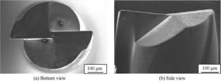
Fig. 1 Morphologies of micro end mill from two different view.
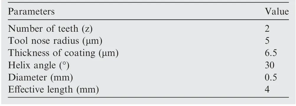
Table 2 Parameters of micro end mill.
Scanning electron microscope(Hitachi S-4800,SEM)was used to observe the morphologies of the generated oxide layer, the machined microgroove bottom and tool wear of the micro end mill. Topography of the microgroove was measured by Digital microscope (Olympus, DSX 1000). Measurement of the milling force was performed with a piezoelectric dynamometer (Kistler 9256C1) which had the threshold force of 0.002 N and the maximum sampling frequency of 30 kHz.The bottom quality of the machined microgroove was characterized using a 3D confocal surface profiler (Phase Shift MicroXAM-3D). The hardness of sub-layer and substrate were measured using a Vickers hardness tester (HV-50Z) with a diamond pyramid indenter under a load of 10 kg and keeping time of 10 s.In order to assess dimensional accuracy of the fabricated microgrooves by LOMM and COMM processes,the top width and bottom width errors were characterized with the following formulas, as reported with Eqs.(1)-(2).

where MTW and MBW are the measured top width and bottom width of the microgroove after micro machining, respectively. DTW and DBW are the nominal width and both sizes are 500 μm.
3. Results and discussions
3.1. Oxidation mechanism of the WC-20%Co material
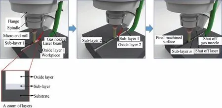
Fig. 2 A schematic diagram on procedure of LOMM.
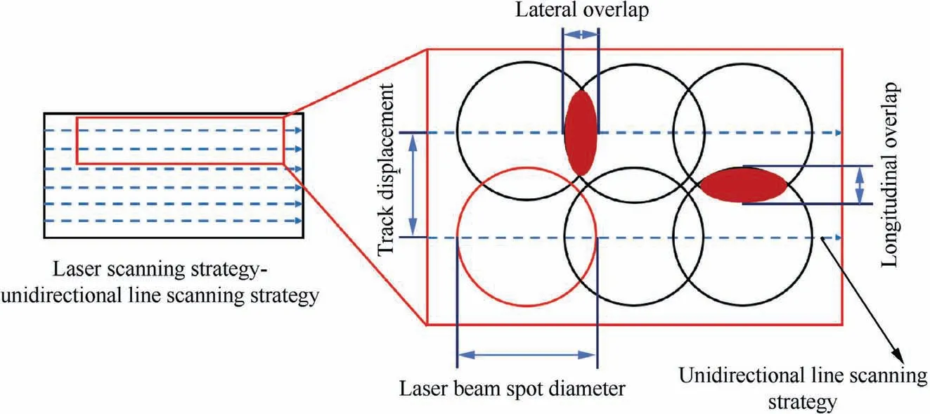
Fig. 3 Schematic diagrams of laser scanning strategy and laser overlap rate.

Fig. 4 A schematic diagram of oxidation process of WC-20%Co material under laser irradiation.
Large amounts of energy generated by the laser can be delivered to designated area of the material to be processed,resulting in the increase of temperature and interaction/response of the workpiece material. Under atmospheric air condition and elevated temperatures induced by the laser beam,the oxidation reaction of cemented carbide material can take place, producing the oxides. In a thermodynamic analysis of the oxidation reaction, the standard Moore Gibbs free energy (ΔG) is characterized as a thermodynamic criterion to determine the possibility and trend of the oxidation reaction of the materials.The more negative of ΔG value is,the greater the possibility of oxidation reaction is.The schematic diagram of oxidation process related to WC-20%Co material is presented in Fig. 4. At the initial stage of laser irradiation, oxygen is conveyed onto the surface of WC-20%Co material surface by gas nozzle. Based on the calculation of Moore Gibbs free energy of WC-20%Co material oxidation reaction, the Co phase distributed between the grains of cemented carbide material first undergoes oxidation reaction, producing the oxides of CoO. As the oxidation reaction proceeds, WC grains start to oxidize with the oxygen, generating the oxides of WOand COgas.At the same time,the oxides of CoWOis also produced under the oxidation reaction. In addition, characteristics of CoWOis more stable than CoO, thereby the oxides of Co phase and WC phase mainly including CoWOand WO.With the overflow of COgas, the oxide layer becomes loose and porous.Furthermore, as oxygen enters into the interior of the oxide layer quickly, the oxidation reaction of WC-20%Co material is accelerated to proceed,resulting in the thickness of the oxide layer increasing gradually.
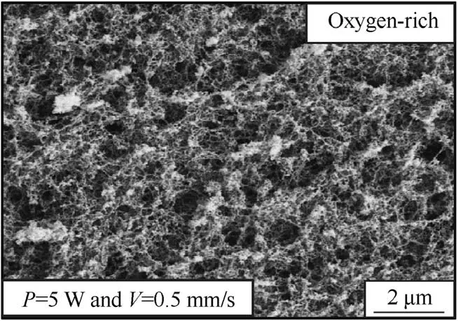
Fig. 5 Morphology of oxide layer in oxygen-rich atmosphere condition.
Fig.5 shows the surface morphology of the oxide layer produced by laser-induced oxidation in oxygen-rich atmosphere condition. Combined with EDS analysis shown in Fig. 6, the oxygen content of the produced oxide layer indicates that the oxygen can promote the generation of the oxides. As the oxidation reaction occurs, the oxides produce and then the oxide layer forms,which implies the hardness of the workpiece material in the confined area to be processed can be decreased effectively. Thus, laser-induced oxidation process can improve the micro machinability of WC-20%Co material in oxygen-rich atmosphere.
3.2. Milling force
Fig. 7 shows the evolutions of the milling force including cutting force (F) and thrust force (F) in LOMM and COMM processes with increasing the depth of the microgroove.Before micro milling of the oxide layer,the final sub-layer and a bit of substrate materials, the gas nozzle needs to be shut off, which aims to prevent the flowing effect of oxygen on measuring the milling force.It can be observed from Fig.7 that with an increment of the depth of the microgroove,the milling force in two directions increases gradually in COMM. In COMM, as the depth of the microgroove reaches 1.6 mm, the first micro tool can’t accomplish the fabrication of the microgroove because of the breakage of the micro tool. Meanwhile, the Fand Fis 6.2 N and 6.1 N, respectively. Low flexural stiffness and strength are the characteristics of micro milling tool because of their extremely small diameter,during micro milling of high hard materials process,which affects the cutting process negatively under the high cutting force, resulting in sudden tool breakage.To achieve the whole machining process in COMM,a new micro tool is used to continue to machine the microgroove.
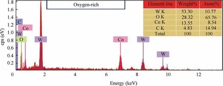
Fig. 6 EDS spectrum of oxide layer.
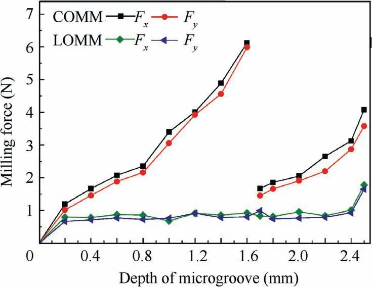
Fig. 7 Milling force increased with depth of microgroove.
Unlike COMM, the milling forces (both Fand F) are extremely low in LOMM process, and they have slight fluctuation in removing the oxide layer process. As the depth of the microgroove reaches 2.40 mm, the oxide layer generated from the procedures of‘‘laser-induced oxidation followed by oxides removal” is removed, which results in the cutting force and thrust force are around 1 N merely, respectively. After removing the oxide layer, the hardness of the sub-layer is measured as 980 HV, which is lower than that of the substrate material.When the depth of the microgroove is beyond 2.40 mm in LOMM, both Fand Fincrease gradually, which is similar to those in COMM. It can be noted that the milling force in LOMM is significantly lower than that in COMM. Furthermore, the final sub-layer and a bit of substrate materials are removed when the depth of the microgroove exceeds 2.40 mm in LOMM. In this process, both Fand Fincrease sharply, attaining 1.8 N and 1.6 N respectively while the microgroove depth is 2.50 mm. Compared with increased milling force in process of removing the final sub-layer and a bit of substrate materials, it indicates that the hardness of WC-20%Co cemented carbide material can be decreased by laser-induced oxidation, thereby improving the machinability of the material and reducing the milling force.Compared with the cutting forces in removing the final sub-layer and a bit of substrate materials (2.40-2.50 mm of the microgroove depth),the cutting forces in removing the oxide layer (0-2.40 mm of the microgroove depth) are relatively low, indicating that the micro machinability of cemented carbide is improved with the assistance of laser-induced oxidation.
3.3. Dimensional accuracy and surface quality of the machined microgroove
3D topography of the machined high aspect ratio microgroove by LOMM and COMM is illustrated in Fig.8.In LOMM,the top and bottom widths of the microgroove are 505 μm and 486 μm respectively, as displayed in Fig. 8(a). It is observed that the cross-sectional geometry of the machined microgroove is a trapezoid,which results from the tool wear during removing the final of sub-layer and a bit of substrate materials. In addition, perpendicularity of the sidewall machined by LOMM is better than that by COMM. Based on Eqs. (1)and (2), the largest errors of the top width and bottom width of the fabricated microgroove by LOMM are 1% and 2.8%,respectively. Whereas, in COMM, the top and bottom widths of the microgroove are 512 μm and 387 μm shown in Fig.8(b),respectively. The cross-sectional geometry of the microgroove is also a trapezoid, and the sidewall is curved. In addition,the largest errors of the top width and bottom width of the fabricated microgroove by COMM are 2.4% and 22.6%, respectively. Therefore, the results indicate that dimensional accuracy of the microgroove fabricated by LOMM process is superior to that by COMM process.
SEM images of the microgroove entrance are displayed in Fig. 9. It’s seen that the microgroove entrance in LOMM shown in Fig. 9(a) is superior to that in COMM presented in Fig. 9(b). The microgroove has micro-bend on the sidewall near the bottom by LOMM, and there is some micro flaking existing in the entrance of the microgroove. Whereas in COMM, large areas of micro flaking occur on the entrance of the microgroove.In addition,perpendicularity of the microgroove machined by COMM is less than that by LOMM,which deteriorates dimensional accuracy of the microgroove.Owing to a reduction of effective diameter of the micro end mill resulting from severe tool wear in COMM, there is an arc shape existing between the sidewall and the bottom.Fig. 10 describes the morphology of the microgroove bottom machined by LOMM and COMM. It’s observed that the bottom surface quality in LOMM is better than that in COMM.As shown in Fig. 10(a), the surface of the machined bottom has no obvious cutting traces. However, during removing the substrate materials process,the rapid tool wear makes the cutting force increase gradually,which results in the extraction of WC particles out of the workpiece material.Thus,some minor cavities are also observed on the surface. In addition, the surface roughness Sin LOMM is 88 nm,while that in COMM is 234 nm. In COMM, the machined surface of the microgroove has obvious cutting traces,and severe surface damages including micro burrs and micro cavities occur on the bottom of the fabricated microgroove, as presented in Fig. 10(b).
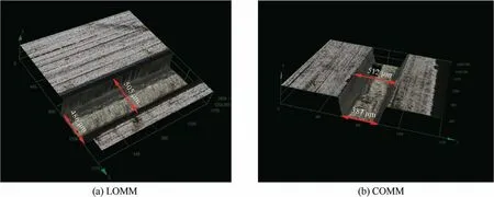
Fig. 8 3D images of machined microgroove in two machining methods.
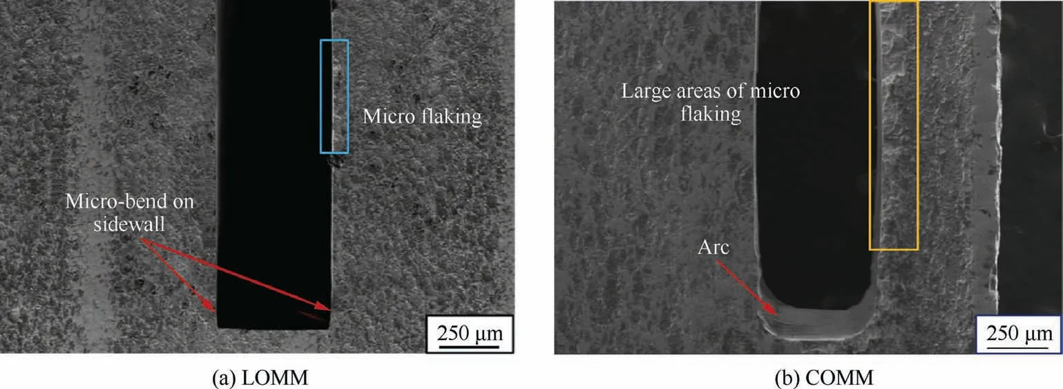
Fig. 9 Morphologies of microgroove entrance in two machining methods.
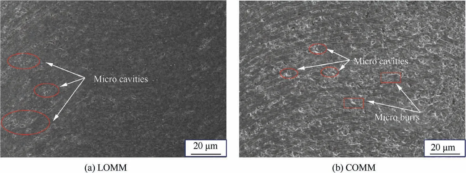
Fig. 10 SEM images of machined microgroove bottom in two machining methods.
3.4. Tool wear
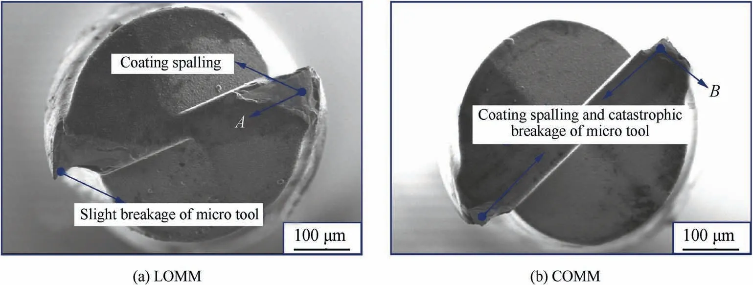
Fig. 11 Wear of micro end mill from bottom view in two machining methods.
Tool wear is a significant factor in evaluating the processing way, which is related to machining economy and dimensional accuracy of the microgroove in micro machining process.Wear morphologies of the micro end mill after machining the microgroove by LOMM and COMM are illustrated in Fig. 11. In LOMM, abrasion wear observed in Fig. 11(a) is the main wear mechanism. The coating spalling, one type of abrasion wear, occurs on the flank face. In LOMM, most of the cemented carbide material is removed as a form of oxides.During removing the oxide layer, the low milling force reveals that the micro end mill doesn’t exhibit obvious tool wear. In machining mode of ‘‘laser-induced oxidation followed by oxides removal”, all the produced oxide layer is removed completely and the depth of microgroove reaches 2.4 mm.Consequently, when the depth of microgroove exceeds 2.4 mm, the materials to be removed include final sub-layer and thin substrate materials. Because the hardness of the sublayer is lower than that of the substrate material, tool wear of the micro end mill is relatively small during removal of the final sub-layer and thin substrate material. EDS spectrum(shown in Fig. 12) reveals that the elements of point A (presented in Fig.11(a))are W,C,Ti,and Co phase,and these elements are main compositions of the cemented carbide substrate. This is because the flank face exhibits severe wear when removing the final sub-layer and a bit of substrate materials,making the micro end mill exhibit rapid coating spalling,thereby resulting in the exposure of the substrate material of the micro end mill. In COMM, the wear image of the second micro end mill is displayed in Fig. 11(b). In comparison with that in LOMM, the micro end mill in COMM has severe tool wear,and the wear types are large areas of coating spalling and catastrophic failure of the tool nose.Because of the high hardness of the WC-20%Co workpiece material, the high milling force produced in COMM of workpiece material causes rapid flank face wear and decrease of effective diameter of the micro tool. In this case, the micro end mill shows the occurrence of coating spalling. In addition, EDS spectrum analysis (shown in Fig.13)demonstrates that main elements of point B are also W,C,Ti,and Co phase and these are main compositions of the cemented carbide substrate. Furthermore, with increasing the depth of microgroove during micro cutting process,the cutting force increases gradually, and tool deflection and bending stress increase sharply, which leads to catastrophic breakage of the tool nose in COMM.
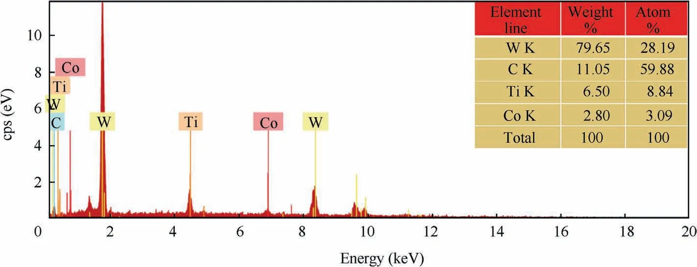
Fig. 12 EDS spectrum of point A in Fig. 11(a).

Fig. 13 EDS spectrum of point B in Fig. 11(b).
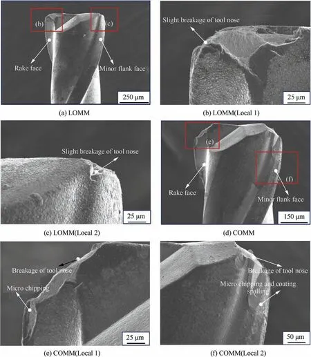
Fig. 14 Morphologies of tool wear from side view in two machining methods.
Fig.14 illustrates wear of the micro end mill from side view in LOMM and COMM processes. It is seen that wear degree of the micro end mill in LOMM is less than that in COMM.With removing the final sub-layer and a bit of substrate materials, the wear rate of the micro tool increases gradually. In addition, tool deflection caused by the milling force is low in LOMM, thereby no obvious wear of spiral edge and minor flake face is observed from Fig. 14(a). However, micro chipping occurs on the major cutting edge and slight breakage of tool nose(presented in Fig.14(b)and Fig.14(c)),which results from the high milling force induced by removing the substrate materials, compared with that in milling the oxide layer process.In addition,large areas of the cemented carbide substrate of micro tool is observed from Fig.14(b). In COMM,the second micro tool wear is extremely serious and wear morphologies are presented in Fig. 14(d) and Fig. 14(f), including the breakage of the tool nose, micro chipping of spiral edge and coating spalling of the minor flank face.During removing high hardness workpiece materials process by COMM, because of minor milling parameters, tool wear occurs on the tool nose mainly. In micro milling of microgrooves, with an increase of the depth of the microgroove and poor rigidity of micro tool with large length-to-diameter ratio, high milling forces are occurring. After that, large tool deflection is induced by high milling force, resulting in micro chipping of the spiral edge and severe minor flank face wear.
4. Conclusions
(1) In this work, an innovative hybrid machining process named as laser-induced oxidation assisted micro milling(LOMM) was proposed to machine WC-20%Co material. Under laser irradiation a loose and porous oxide layer which is composed of CoWOand WOwas produced in oxygen-rich atmosphere condition.The milling force was extremely low during removing the oxide layer, indicating that the micro machinability of the WC-20%Co material was improved by the assistance of laser-induced oxidation.
(2) A microgroove with an aspect ratio of 5 and depth of 2.5 mm was achieved by the innovative hybrid process.For a comparison with LOMM,a microgroove was also fabricated by the conventional micro milling (COMM)under identical milling parameters. The milling forces in both cutting direction(F)and thrust direction(F)in COMM during removing the workpiece materials were higher than those in LOMM during milling the oxide layer.In addition,in LOMM,the milling force increased gradually with an increment of the microgroove depth during removing the sub-layer and substrate materials.In COMM, the micro end mill was ruptured due to the high milling force when the microgroove depth was 1.6 mm.
(3) The machined surface quality of the microgroove bottom achieved by LOMM was superior to that obtained by COMM. The surface roughness Swas 88 nm in LOMM while that reached 234 nm in COMM, at f=1.5 μm/z and a=2 μm. Perpendicularity of the microgroove sidewall machined by LOMM was better than that obtained by COMM. In addition, the tool wear of the micro end mill in COMM was much more severe than that in LOMM. Coating spalling, slight micro chipping of the spiral edge and breakage of the micro tool nose were main tool wear forms in LOMM.Whereas, in COMM, severe spiral edge wear, micro chipping and coating spalling of the minor flank face and severe tool nose breakage were the main tool wear forms.
In the future work, the proposed innovative method of LOMM can machine curved micro-features and 3D complex form shapes which are related to wide applications of micro dies and molds on cemented carbide material. In addition,laser-induced oxidation is expected to apply for assisting macro machining, which is important for industrial relevance.Besides, dimensional accuracy of the micro-feature fabricated by LOMM needs to be further improved, thereby achieving high-precision and high-quality micro-features.
Declaration of Competing Interest
The authors declare that they have no known competing financial interests or personal relationships that could have appeared to influence the work reported in this paper.
Acknowledgement
sThis work was supported by the National Natural Science Foundation of China(No.51705249),and the China Postdoctoral Science Foundation (No. 2019M661823), and the Aeronautical Science Foundation of China (No. 2017ZE52047),and the 111 Project on Key Technology in Sustainable Manufacturing (No. B16024).
 CHINESE JOURNAL OF AERONAUTICS2021年4期
- CHINESE JOURNAL OF AERONAUTICS的其它文章
- Time delay compensation in lateral-directional flight control systems at high angles of attack
- Dual stability enhancement mechanisms of axial-slot casing treatment in a high-speed mixed-flow compressor with various tip clearances
- Development cost prediction of general aviation aircraft using combined estimation technique
- Improvement on shaped-hole film cooling effectiveness by integrating upstream sand-dune-shaped ramps
- Modeling and parameter identification of linear time-varying systems based on adaptive chirplet transform under random excitation
- An experimental method to obtain the hard alpha anomaly distribution for titanium alloy aeroengine disks
