Theoretical and experimental investigation on novel 2D maglev servo proportional valve
Bin MENG, Hao XU, Jian RUAN, Sheng LI
Key Laboratory of Special Purpose Equipment and Advanced Manufacturing Technology Ministry of Education, Zhejiang University of Technology, Hangzhou 310018, China
KEYWORDS Dynamic characteristic;2D valve;Maglev coupling;Servo proportional valve;Stability criterion
Abstract This paper presents a novel two-dimensional maglev servo proportional cartridge valve(2D maglev valve), where a contactless maglev coupling is introduced between electro-mechanical converter and valve body to realize functions of force transmission, spool position feedback and linear-rotary motion conversion.Such configuration can effectively reduce cost of both valve manufacturing and electro-mechanical converter, while still maintain features of 2D valve such as null pilot leakage,high power-to-weight ratio and excellent anti-pollution capacity.Firstly,the characteristic equation of the valve is derived using linear theory,and the stability criterion is established for parameter determination.The influences of crucial structural parameters such as initial height of overlapping area, width of high-pressure and low-pressure holes, acting radius of magnetic force,pitch angle of maglev coupling, length of sensitive chamber and system pressure on the dynamic response are investigated based on AMESim numerical simulation. The prototype valve is then designed and manufactured and a special test rig is built.The no-load flow characteristic,load flow characteristic, leakage characteristic, amplitude and phase frequency characteristics and step response under different system pressures are measured. The experimental results are in a good agreement with the simulated analysis.As an over-damped system,the prototype valve has excellent working stability, which can reach a no-load flow rate of 105.9 L/min with hysteresis of 3.51%,amplitude bandwidth of 28.7 Hz and phase bandwidth of 42.8 Hz under 21 MPa.The research indicates that the 2D maglev valve can be a potential solution of flow rate control valve for flight control surface system of civil aircraft with high pressure and large flow rate application.
1. Introduction
Since its advent, electro-hydraulic control system has been widely used in aviation since it successfully integrates features of fast dynamic response, high power-to-weight ratio, large rigidity and convenient signal transmission and processing with electronic technology.The aircraft electro-hydraulic system includes main flight control surface system, auxiliary flight control surface system, landing gear system and functional system. For these flight control surface systems, an electro-hydraulic servo actuator (EHSA) is used to realize servo control with high accuracy and fast response.The EHSA is mainly controlled by an electro-hydraulic flow rate servo valve, where for civil aircraft the dynamic response requirement of such valve is basically between 25-40 Hz,and military aircraft would demand higher dynamic response.
As crucial control components,servo valve plays a key role for the performance of the whole electro-hydraulic system.Servo valve is generally divided into direct driving valve and pilot operated valve. Due to limited thrust force of electromechanical converter (EMC), direct driving valve can only be used for low pressure and small flow rate situations.In order to effectively overcome the influence of Bernoulli force and friction force brought by high pressure and large flow rate condition,servo valve must be designed as pilot operated configuration so that the output force of EMC can be amplified to a level sufficient to shift the main spool.Common pilot operated servo valve includes nozzle flapper valve, jet pipe valve,moving coil valve and so on.Nozzle flapper valve and jet pipe valve are driven by torque motor, which has high control precision and fast dynamic response,and is widely used in various flight attitude control of aircrafts. However, Nozzle flapper valve has poor anti-pollution ability and complicated structure,while jet pipe valve has excellent anti-pollution ability owing to its unique pilot stage,but the jet flow field is complex and the characteristics are difficult to predict.Besides,both valves have a certain degree of self-excited oscillation problem.To improve dynamic response,some servo valves are driven by a moving coil motor with very large exciting current,which is therefore called as moving coil valve.Such valve usually requires an additional cooling device for heat dissipation.After the end of World War II, electro-hydraulic servo technology was transferred to civil industry, and proportional valve appeared accordingly where some novel configurations pilot operated valves have emerged.In recent years,servo control and proportional control technologies start to mutually integrate. And the so-called servo proportional valve has emerged and been applied on aircraft flight control system.This valve is directly driven by a linear electro-mechanical converter(LEMC)with large excitation current,and its spool displacement is fed to controller using LVDT transducer to obtain better static and dynamic characteristics. This servo proportional valve features high working stability and low manufacturing cost. However, its maximum flow rate is still only about 120 L/min due to limited thrust force of LEMC.Besides, some novel valves use modern functional materials,such as piezoelectric crystal,giant magnetostrictive material,magnetorheological fluid and shape memory alloy as EMC,which feature very fast dynamic response of several kHz. However, the properties of these materials are greatly affected by temperature variation and nonlinear hysteresis.
A spool valve usually has two degrees of freedom (DOFs),i.e. linear and rotary, therefore, people might utilize these two distinct motions simultaneously to figure out novel valve configurations.Ruan et al. proposed so-called two-dimensional valve(denoted as 2D valve),which successfully integrates pilot stage and power stage into one single spool and therefore features very simple structure, high power-to-weight ratio and excellent anti-pollution ability.For such advantages, 2D valve has been used as flow rate control valve and directional valve on aircraft electro-hydraulic systems, such as flight control surface system,weapon injection system and airplane door opening system. However, such configuration has two issues worthy of discussion, as shown in Fig. 1: firstly, it needs to machine a spiral sensing groove on the inner surface of valve sleeve, which is used to form pilot stage together with highpressure and low-pressure holes on the spool land to control sensitive chamber pressure, and therefore create hydrostatic force difference to drive spool.Manufacturing such spiral groove not only requires EDM machine with at least three axes,but also is time-consuming,which means both machining cost and processing efficiency are unsatisfactory.Secondly,the valve requires a rotary electro-mechanical converter (REMC)to rotate spool in order to actuate ‘‘2D” mechanism.Nevertheless, unlike mass-produced commercial proportional solenoid, REMC is less unpopular and therefore quite expensive,and it is difficult to obtain flat torque-angle characteristics since REMC with proportional characteristics usually needs special magnetic circuit topology and proper parameter optimization.Thus, such valve scheme has shortcomings of very high cost coming from both manufacturing and EMC,which greatly influence its mass promotion and application to the aviation and other industries.
In order to reduce the overall cost of 2D valve, this paper presents a configuration of novel 2D maglev servo proportional cartridge valve (denoted as 2D maglev valve), where a contactless maglev coupling is introduced between EMC and valve body to realize force transmission, spool position feedback and linear-rotary motion conversion. The advantage of this configuration is that the complicated spiral sensing groove can be replaced by a simple rectangular sensing groove and commercial proportional solenoid can be available as valve EMC, where the former can reduce manufacturing cost and the latter can greatly decrease the EMC cost.
The rest of this paper is organized as follows: In Section 2,the configuration and working principle of 2D maglev valve is introduced.In Section 3,the characteristic equation is deduced using linear theory and working stability criterion is established.In Section 4,influence and sensitivity of critical parameters on valve dynamic response are investigated using AMESim simulation.In Section 5,prototype valve is designed and machined and its static and dynamic characteristics are tested with a special test rig. The experiment results are compared with simulated analysis. Finally, some conclusions of this work are drawn in Section.6.
2. Configuration and working principle
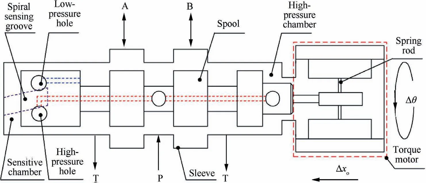
Fig. 1 Working principle of traditional 2D valve with spiral sensing groove.32
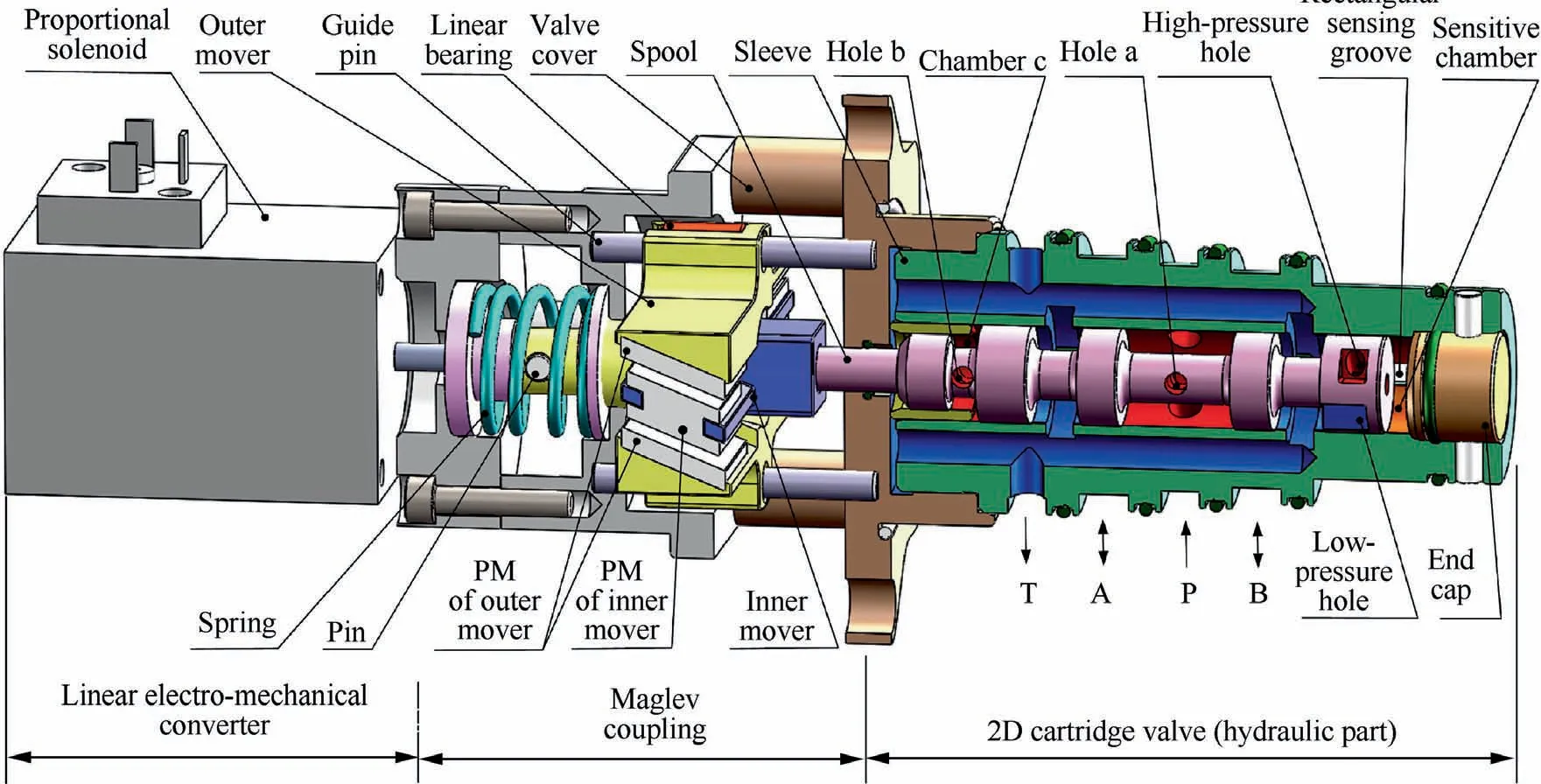
Fig. 2 Schematic diagrams of two-dimensional maglev servo proportional cartridge valve (2D maglev valve).
Fig. 2 show a schematic for the configuration of novel 2D maglev valve.It consists of proportional solenoid,maglev coupling and 2D cartridge valve. Armature of proportional solenoid is fixed with outer mover, and its thrust force is converted to linear displacement through a mechanical spring.The maglev coupling mainly includes outer mover, inner mover, permanent magnet, linear bearing, guide pin and so on.The polar surface of the outer mover and the wing surface of the inner mover are designed to slopes with same pitch angles,where the slopes on the left and right sides are arranged by 180°array.One end of the guide pin is fixed with the valve cover, and the other end is inserted into the linear bearing, so that the outer mover can only move linearly, while the inner mover can move linearly and rotationally.The pole surfaces of the outer mover and the wing surfaces of the inner mover are all pasted with sheet permanent magnets(PM),and those PMs located face-to-face should have the same polarity in order to obtain magnetic repulsion force in working air gaps. Therefore,the inner mover can be magnetically levitated in the middle of the outer mover without any mechanical structure,which avoid unfavorable influence from friction and wear on valve static characteristics. The hydraulic part of 2D maglev valve adopts cartridge configuration, which mainly including sleeve, spool and end cap. On the right land of spool there are two rectangular holes, denoted as high-pressure and lowpressure hole, which are connected to oil supply and tank,respectively. There is a rectangular sensing groove manufactured on the inner surface of sleeve, which is connected to the sensitive chamber on the right end of spool. In neutral position, high-pressure and low-pressure holes are distributed on the two sides of sensing groove to constitute two tiny rectangular overlapping openings in order to form hydraulic half bridge resistance,and oil flow out of these openings are mixed and then piloted to the sensitive chamber through sensing groove. Besides, oil with supply pressure is also piloted to chamber c through port P,hole a and hole b.The annular area of chamber c is designed to be 32/81 of the sensitive chamber area.
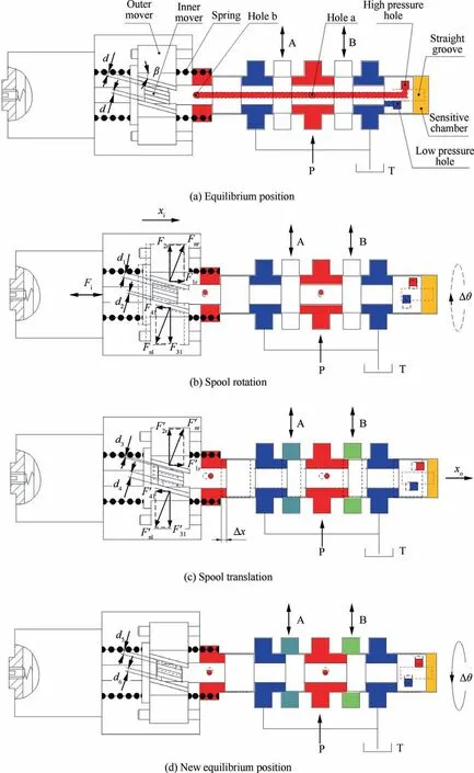
Fig. 3 Working principle of 2D maglev valve.
Fig. 3 illustrates working principle of 2D maglev valve in detail. When proportional solenoid is not energized, the valve is in a pre-adjusted neutral position, where the height of all working air gaps of the maglev coupling are all equal(denoted as d),as shown in Fig.3(a),and the high-pressure hole has the same overlapping height with respect to sensing groove as does low-pressure hole.Therefore,the pressure of sensitive chamber regulated together by the oil of high-pressure and low-pressure holes is 32P/81. Given that the Bernoulli force and Coulomb frictional force can be overlooked as their magnitude is much smaller than hydrostatic force,the spool is under a state of static balance. When solenoid is energized, the outer mover is pushed to move towards left,so that the heights of the working air gaps changes (dand d, d>d , d<d), therefore, the magnetic repulsion force Fin the air gap decreases (Fcan be decomposed into axial force Fand tangential force F),and the magnetic repulsion force Fincreases (Fcan be decomposed into axial force Fand tangential force F).The resultant force of the tangential forces Fand Fmakes the resultant moment of the inner mover unbalanced, thus drive the spool to rotate anticlockwise,and this rotary motion changes two overlapping openings differentially, which varies the sensitive chamber pressure from its initial state value and cause the imbalance of hydrostatic force acting on the spool,therefore the spool moves right, as shown in Fig. 3 (b). This linear motion of spool results in the changes of heights of the working air gaps (dand d, d<d, d>d), as shown in Fig. 3 (c), which leads to the reverse rotation of the spool until the heights of the working air gaps return to their initial value (d=d=d), and the overlapping openings of highpressure and low-pressure holes with sensing groove equals again, as shown in Fig. 3 (d). As a result, a force balance is re-established across the spool and the spool is in a new equilibrium position. In the above process, the maglev coupling acts as both a conversion of linear-rotating motion and a feedback mechanism of spool position. The spool opening chases the displacement of solenoid armature at 1:1 ratio. Naturally,the 2D maglev valve is a mechanical-hydraulic closed-loop feedback mechanism.
3. Stability analysis
For pilot operated servo valve, the primary design task is to ensure its working stability, then followed by the pursuit of good static and dynamic characteristics. From view of electro-hydraulic servo control theory, 2D maglev valve can be regarded as a mechanical-hydraulic closed-loop control system where a three-way spool valve is used to control a differential hydraulic cylinder,as shown in Fig.4.The input signal is the armature displacement of proportional solenoid and the output signal is the spool displacement. Static and dynamic characteristics of electro-hydraulic control system can be adjusted by control algorithm.However,the static characteristics of mechanical-hydraulic control system is basically determined by manufacturing process, and its dynamic features are largely determined by structural parameters. Therefore, it is necessary to establish the characteristic equation of 2D maglev valve and analyze the influence of crucial structural parameters on its working stability and dynamic characteristics.
3.1. Characteristic equation
The maglev coupling is used to transfer the armature displacement of proportional solenoid xto spool rotation angleθ.Such relationship can be written as

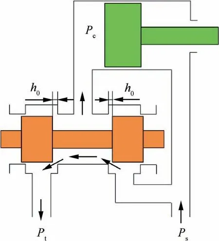
Fig. 4 Schematic of three-way valve controlled differential cylinder.
where R is the distance from acting point of magnetic repulsion force to the rotary center of spool; β is the pitch angle of maglev coupling.
Supposing the magnetic stiffness of the maglev coupling is infinite, based on principle of virtual work, the relationship between solenoid’s thrust force Fand magnetic torque acting on spool M can be written as
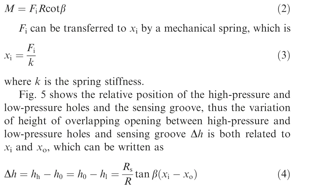
where Ris the spool radius;his the initial height of overlapping opening between high-pressure and low-pressure holes and sensing groove; his the height of overlapping opening between high-pressure hole and sensing groove;his the height of overlapping opening between low-pressure hole and sensing groove; xis the spool output displacement.
The overlapping opening area A(h) can be expressed as
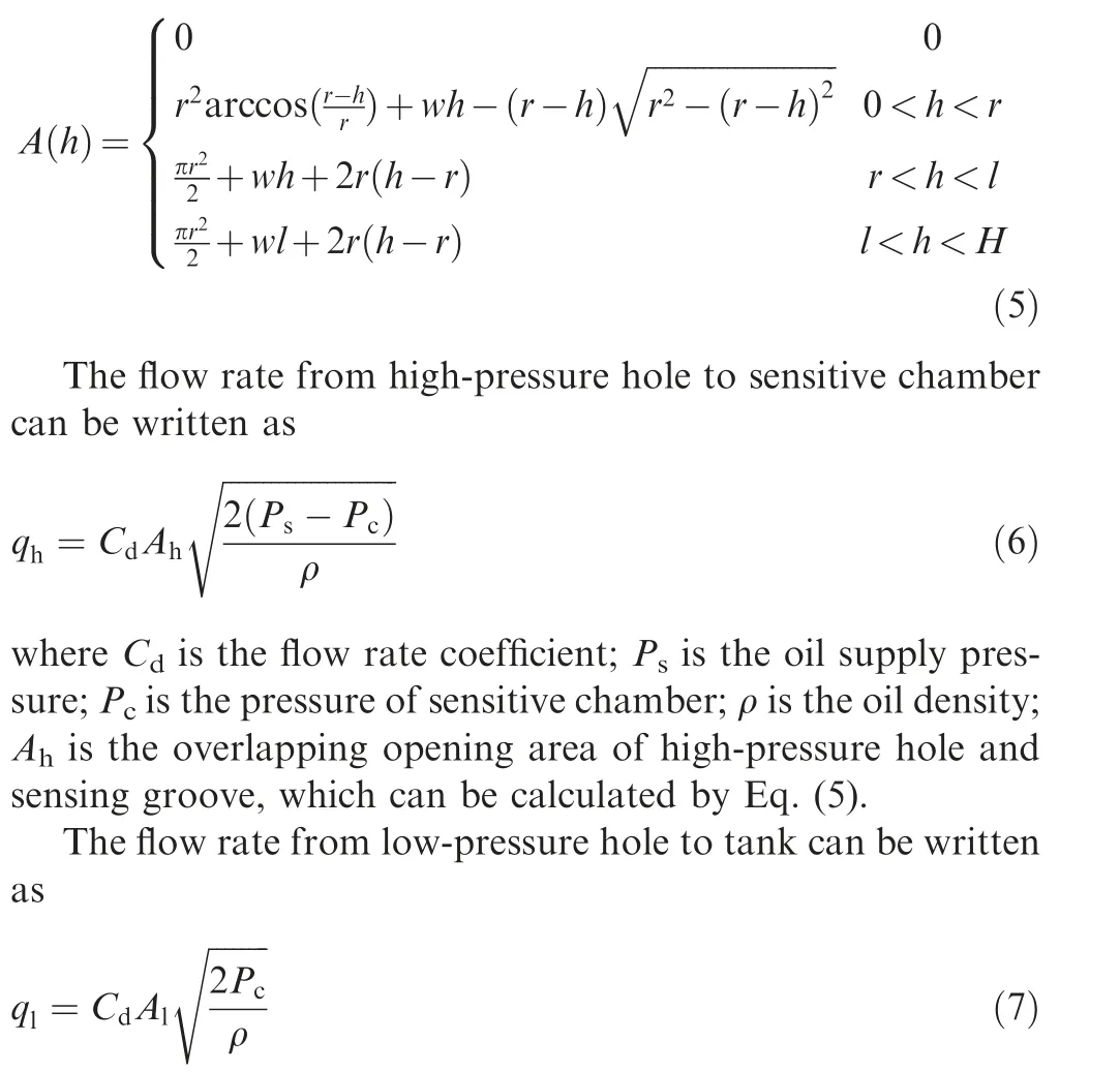
where Ais overlapping opening area of low-pressure hole and sensing groove, which can be calculated by Eq. (5).
The flow continuity equation of the spool sensitive chamber can be written as

where qand qare the leakages through the spool-sleeve clearances at the sides of high-and low-pressure holes; Ais the sensitive chamber area;βis the elasticity of bulk modulus;Vis the sensitive chamber volume.

Fig. 5 Relative position of high-pressure and low-pressure holes and sensing groove.
Regardless of the influence of the Bernoulli force and Coulomb frictional force, the force balance equation of spool can be written as
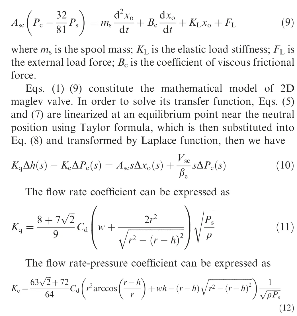
Together with Eq. (10), the closed-loop transfer function block diagram of 2D maglev valve can be obtained after the Laplace transformation of Eqs.(4)and(9),as shown by Fig.6.
3.2. Working stability criterion
According to Fig. 6, the closed-loop transfer function of 2D maglev valve can be written as
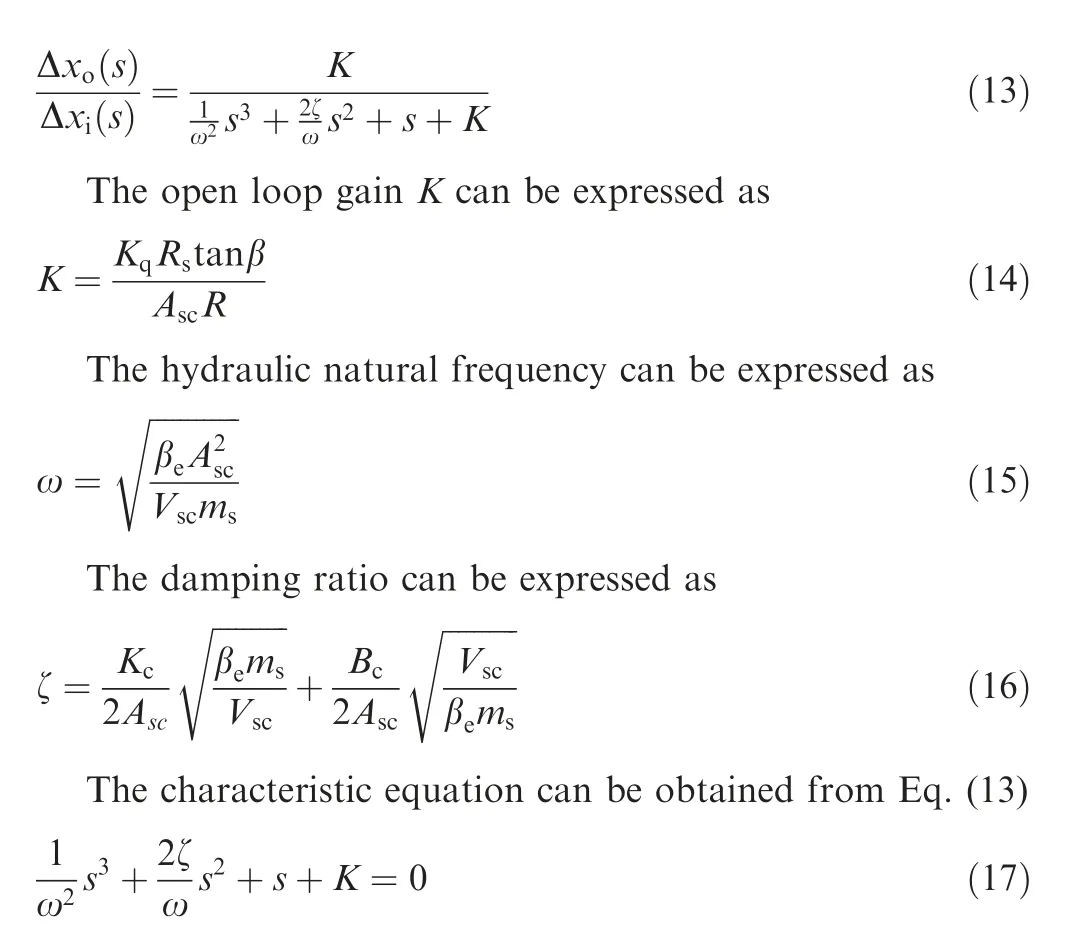
Using Routh criterion, the Eq. (17) can be rewritten as K <2ζω (18)
Finally, the working stability criterion of 2D maglev valve can be written as

where Lis the length of sensitive chamber.

Fig. 6 Flow chart of 2D maglev valve.
The stability criterion given in Eq. (19) is the design guidance for the 2D maglev valve since any crucial parameter selection should satisfy Eq. (19) firstly in order to ensure working stability.The criterion also indicates the influence of some crucial structural parameters on the working stability of 2D maglev valve. Increasing supply pressure P, valve tends to be unstable. Increasing the initial height of overlapping opening area hwill increase stability,yet with the cost of increasing leakage of pilot stage. Reducing the length of the sensitive chamber Lis expected to improve the stability. With the increase of the flow rate the spool radius Rshould be increased, otherwise the flow rate will be saturated, but large Rwill also lead to the valve instability. The bulk modulus of elasticity βis generally regarded as constant. However,when the valve is operated at high frequency, the pressure of the sensitive chamber changes violently, which could be much lower than the air separation pressure and cause cavitation.When this occurs, βdrops sharply, which not only reduces the hydraulic natural frequency ω and affects the dynamic response, but also causes the instability. To compensate this effect, other parameters should be selected more conservative in order to improve working stability. Increasing pitch angle β can increase the change rate of the permeance of the maglev coupling,thus improve the magnetic torque and valve dynamic response,but large β will also affect the stability.Increasing R can improve the magnetic torque of the coupling and valve working stability simultaneously, and increase the dynamic response, but it will also increase the structural size of the maglev coupling, therefore affect the volume and weight of the whole valve.
It should be noted that Eq. (19) does not consider the viscous frictional effect Band leakage through the spool-sleeve clearance qand q, both of which are actually helpful for the stability since Bimproves system damping ratio directly while qand qimprove flow rate-pressure coefficient.Therefore, the working stability criterion of Eq. (19) tends to be conservative.
4. Dynamic simulation
In order to both guarantee working stability and improve dynamic response, the numerical simulation model of 2D maglev valve is established using AMESim software(Table 1).The purpose of simulation is to study the influence of crucial structural parameters such as initial height of overlapping area h, width of high-pressure and low-pressure holes w, acting radius of magnetic force R, pitch angle of maglev coupling β, length of sensitive chamber Land supply pressure Pon the valve dynamic characteristics. Table 1 shows the main parameters used in the AMESim simulation. Fig. 7 illustrates the AMESim model, which consists of proportional solenoid,maglev coupling, valve pilot stage and valve main stage.
Fig. 8 (a)-(f) illustrate the simulated step response curves from AMESim model.Table 2 summarize the simulated rising time tof step response under different values of parameters.There is no overshoot for the step response, which indicates that the 2D maglev valve with selected parameters in Table 1 is an over-damped system with excellent working stability.Lhas little effect on the dynamic response of the system.Increasing h, w, β, R and Preduces t, and these can be explained by the above-discussed linear theory: increasing hand w would increase flow rate coefficient Kand in turn increase open loop gain K, and then improve dynamic response, as shown in Eq. (11). Increasing βand R would increase output torque of maglev coupling so that the dynamic response would also improve, as shown in Eq. (2). Increasing P, the pressure difference between sensitive chamber and high-pressure chamber of valve will also increase, which is equivalent to the increase of the driving force of spool, therefore the response speed will be improved.Besides,the influenceof P,h,β and w valve dynamics are more obvious than other parameters, which indicates they can be the primary choices for performance optimization. Finally, it should be noted that the characteristics of maglev coupling has important influence on the dynamic response of 2D maglev valve. Besides the above mentionedβand R, other approaches those can increase output torque of maglev coupling, such as small working air gap, permanent magnet with high magnetic energy product and Halbach topology of coupling magnetic circuit, are all helpful to improve valve dynamic response.
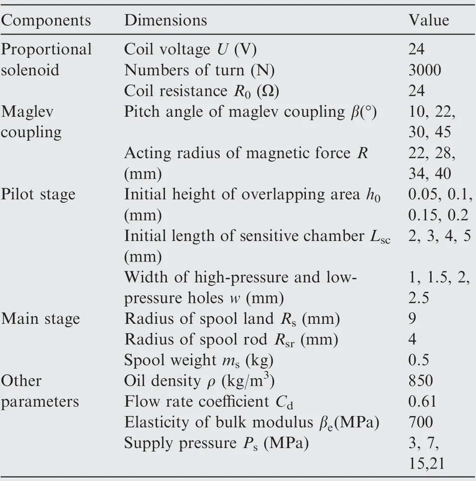
Table 1 Parameters for AMESim simulation.
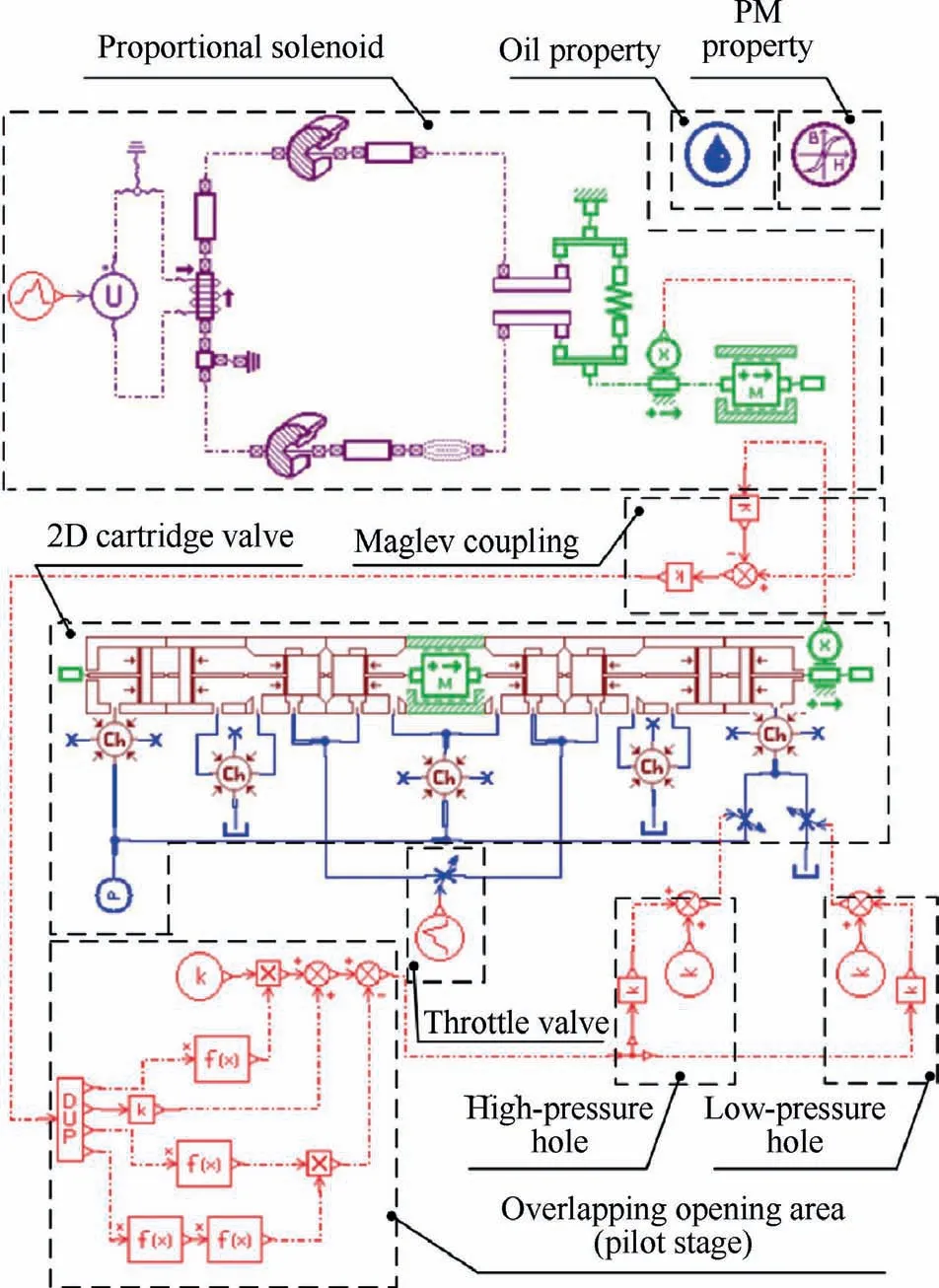
Fig. 7 AMESim model of 2D maglev valve.
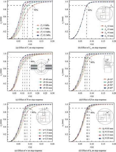
Fig. 8 Simulated step response curves from AMESim model.
5. Experiment study
Based on the working stability analysis and numerical simulation results, the crucial structural parameters are determined and checked by Eq. (19), as listed in Table 3. The prototypeof 2D maglev valve is designed accordingly and manufactured,as shown by Fig. 9. A commercial proportional solenoid(GP45A4-AIW9) is used as the EMC, which is controlled by a home-made digital proportional amplifier. Fig. 10 illustrates the comparison of spiral sensing groove of traditional 2D valve and rectangular sensing groove of 2D maglev valve,where the latter is obviously less complicated and has very lower machining cost.
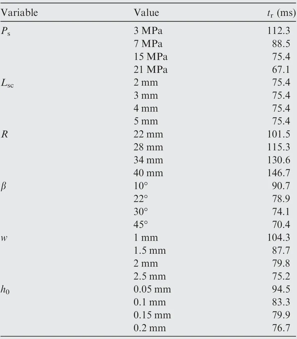
Table 2 Simulated results from AMESim simulation.
In order to measure the static and dynamic performance of prototype valve, a special test rig is established, as shown in Fig. 11. The hydraulic pump source mainly consists of a fixed displacement pump and a relief valve to adjust the pressure to obtain the performance curve under different valve port pressure drop. All four working ports of the prototype valve are equipped with digital pressure gauges. An internal elliptical gear flowmeter is used to measure both the no-load flow rate,load flow rate and leakage flow rate. The test rig switches the hydraulic circuit through the combination of several on-off valves: for the testing of no-load flow rate, on-off valves 7,8,9 should open and 10 and 11 should close,while for the testing of leakage flow rate,on-off valves 7,8,9 should close and 10 and 11 should open.For load flow rate test,a throttle valve is paralleled between port A and port B to simulate external load. Besides, a laser displacement sensor is used to test the amplitude frequency, phase frequency and step response characteristics of the valve,whose input signal is provided by a signal generator. Fig. 12 demonstrates the experiment picture of test rig and valve block for load flow rate test.
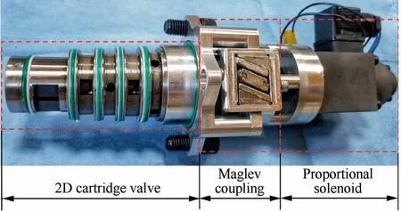
Fig. 9 Prototype of 2D maglev valve.
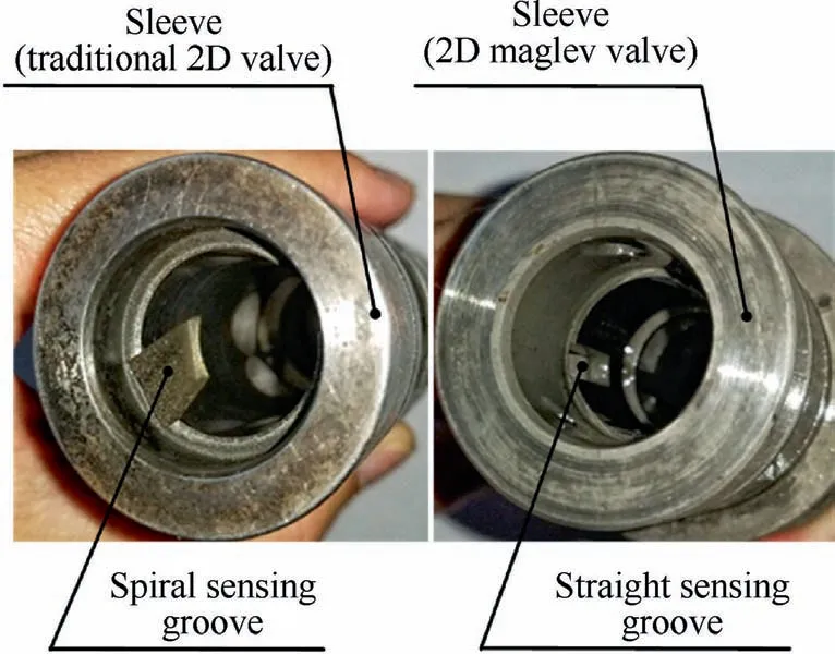
Fig. 10 Comparison of spiral sensing groove and rectangular sensing groove.
5.1. Dynamic characteristics
Table 4 summarizes the experimental and simulated results of the dynamic characteristics for prototype valve with supply pressures of 7 MPa, 15 MPa and 21 MPa, respectively, which include amplitude frequency width,phase frequency width,rising time of step response.The simulation was performed based on the AMESim model presented in Section 3. Fig. 13 (a)-(i)shows the sine wave experimental and simulated frequency response curves, where ‘‘Exp” denotes experimental results and ‘‘AME” denotes simulated counterparts. The output signal of the valve spool can well follow the variation of the input signal in the low-frequency segment,and has a good frequency response in the high-frequency segment. With the increase of the input signal frequency,the amplitude frequency and phase frequency begin to lag gradually.Fig.14 shows the experimental and simulated amplitude frequency and phase frequency characteristic curve. The amplitude bandwidth and phasebandwidth increase with the increase of supply pressure,among which the experimental amplitude bandwidth of -3 dB reaches about 18.8 Hz,24.5 Hz and 28.7 Hz,and simulated counterpart reaches about 20.3 Hz, 26.6 Hz and 29.5 Hz,respectively. And the phase bandwidth of -90° reaches about 26.7 Hz, 36.6 Hz and 42.8 Hz, and simulated counterpart reaches about 27.8 Hz, 37.5 Hz and 45.2 Hz, respectively.Fig. 15 shows the experimental and simulated step response curves, where the experimental rising time is about 118.6 ms,91.3 ms and 68.8 ms, and simulated counterparts reaches about 90.1 ms,77.8 ms and 67.5 ms,respectively.It can be seen that the dynamic response of prototype valve reaches the requirements of flight control surface system of civil aircraft.And if a high frequency EMC such as linear force motor is used as actuator, the dynamic response will be better. Also,the simulation results are in good agreement with the experimental results for both sine wave response and step response,which indicates the AMESim simulation can provide effective theoretical guidance for valve design.The simulated responses are slightly faster than the experimental counterparts, this is mainly due to the difference of parameters used between simulation and real situation (see Figs. 16-18, Table 5).

Table 3 Crucial structural parameters of prototype valve.
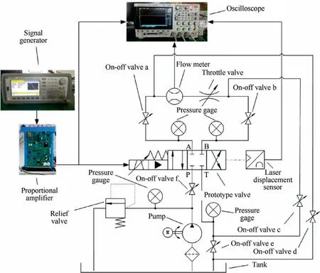
Fig. 11 Schematic of test rig for 2D maglev valve.
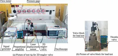
Fig. 12 Experiment picture of test rig and valve block for load flow rate test.

Table 4 Summary of the experimental and simulated results of dynamic characteristics.
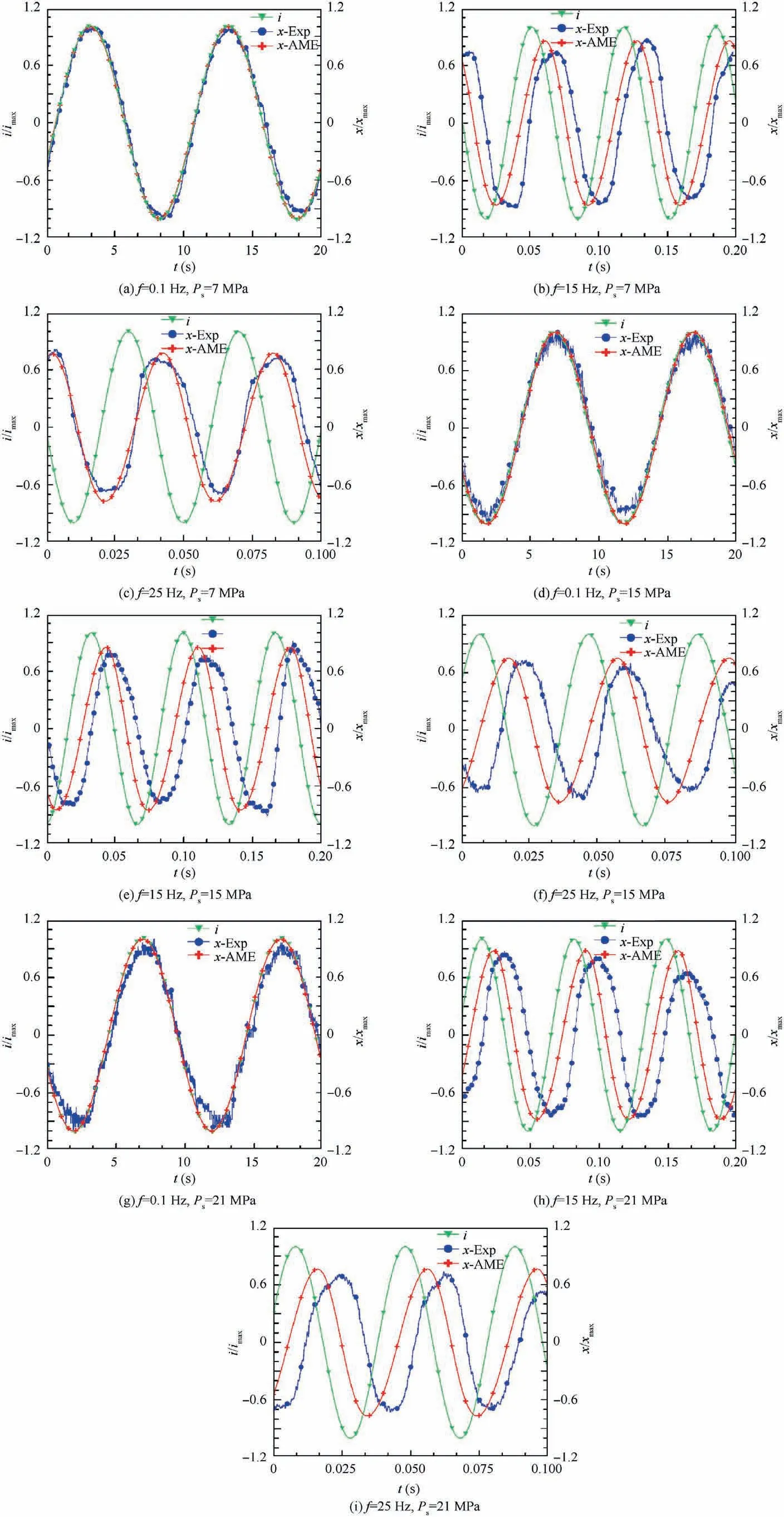
Fig. 13 Sine wave frequency response.
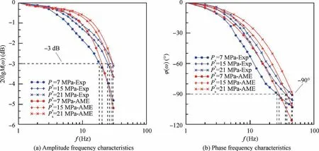
Fig. 14 Frequency response characteristics.
In addition,it can be observed that there is no overshoot of the spool response to the input signal,which means the prototype valve is an over-damped system and has excellent working stability.This is mainly because that the width of high-pressure and low-pressure holes w is chosen to be as small as possible,and this reduce the flow rate gain of pilot stage,which actually sacrifice certain dynamic response,but this also leads to the situation that the hydraulic 2nd oscillating elements of closedloop function has little impact on the dynamic performance of the valve. Therefore, the dynamic characteristics of the valve have no obvious oscillation. Here, both experimental and simulated results prove the effectiveness of working stability deduced in Section.3.
5.2. Static characteristics
The static characteristics is basically determined by manufacturing process. Table 5 summarizes the experimental and simulated results of static characteristics for prototype valve with supply pressures of 7 MPa,15 MPa and 21 MPa,respectively, which include maximum no-load flow, maximum leakage flow and hysteresis. Fig.16 shows the experimental and simulated no-load flow rate characteristic curves. The output flow increases with the increase of supply pressure, where the experimental maximum no-load flow is about 54.3 L/min,78.7L /min and 105.9 L/min, and simulated maximum no[HYPHEN]load flow is about 58.3 L/min, 88.6 L/min and 119.2 L/min, respectively. Without any dither compensation and other closed feedback control, the experimental hysteresis of prototype valve reaches about 5.51%, 4.32% and 3.51%,and simulated hysteresis of prototype valve reaches about 0.88%, 0.75% and 0.59%, respectively, indicating that the valve has good static characteristic. Since AMEsim model doesn’t consider the manufacturing error and pressure loss along the flow path, the simulated flow rates are large than experimental counterparts and the simulated hysteresis is nearly null compared to experimental results. Fig.17 shows the experimental and simulated results of load flow rate curves under different spool openings and different supply pressures.It can be seen that the load flow rate gradually reduces with the increase of load pressure.This also make sense because the 2D maglev valve is essentially a flow rate valve with spool displacement feedback,not flow rate feedback,therefore the load flow rate curve doesn’t have flat characteristics. It should be pointed out that not like the no-load flow characteristic curve,the load flow characteristic curve is dimensionless,and thus the simulation results are closer to the experimental values.Fig.18 shows the experimental and simulated leakage flow rate characteristic curves. The pulse peak shape curve represents the total leakage flow including the leakage oil both from the main valve port and pilot stage port, where the experimental maximum value reaches about 3.5 L/min, 4.5 L/min and 6.9 L/min, and simulated result reaches about 4.5 L/min,6.4 L/min and 8.9 L/min,respectively. The zigzag shape curve represents the leakage flow of the pilot stage,where it is almost null owing to the tiny overlapping area between high-pressure and low-pressure holes and sensing groove. The simulated results are larger than experimental valves.This is also because that the AMEsim model doesn’t account for the manufacturing and assembly error.
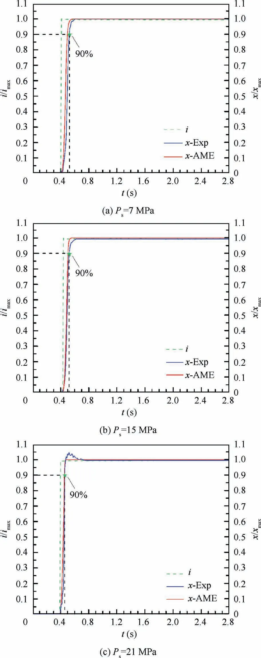
Fig. 15 Step response characteristics.
5.3. Comparison
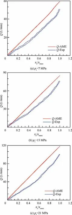
Fig. 16 No-load flow rate characteristics.
In this section, the performances of 2D maglev valve and an existing traditional 2D valve are compared preliminarily, as shown in Table 6. The experimental data of traditional 2D valve are derived from published literature.Since the structural parameters of these two valves are different,the comparison meaning of maximum flow rate is not so significant.However, the dynamic characteristics and hysteresis can be compared if the maximum flow rate is treated as the‘‘anchor”.For traditional 2D valve the amplitude bandwidth of -3 dB and phase bandwidth of -90° reach about 140 Hz at 25%spool stroke,both of which would be 35 Hz if we convert them to the values at 100% spool stroke. For 2D maglev valve the corresponding valves at 100% spool stroke are 28.7 Hz and 42.8 Hz, respectively. Since the maximum flow rate of the former is greater than that of the latter, it can be concluded that its dynamic performance should be slightly better than that of 2D maglev valve,which is also because that the traditional 2D valve uses hybrid stepping motor with closed-loop control as its EMC. In addition, the hysteresis of traditional 2D valve and 2D maglev valve is about 3.51% and 2.2%, respectively.Since the EMC of the former is under closed-loop control,while the 2D maglev valve is purely under open-loop control,we can say that the latter has good static characteristics because of non-contact working mechanism of magnetic coupling. In terms of the cost, comparison between spiral sensing groove and straight sensing groove has been discussed previously. It should also be noted that the market price of hybrid stepping motor(FL42STH47-1684A)is about 4 times as much as that of the proportional solenoid (GP45A4-AIW9), and closed-loop control also increases the overall cost. Therefore,the cost advantage of 2D maglev valve is validated.
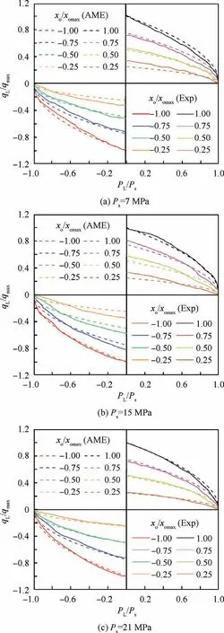
Fig. 17 Load flow rate characteristics.
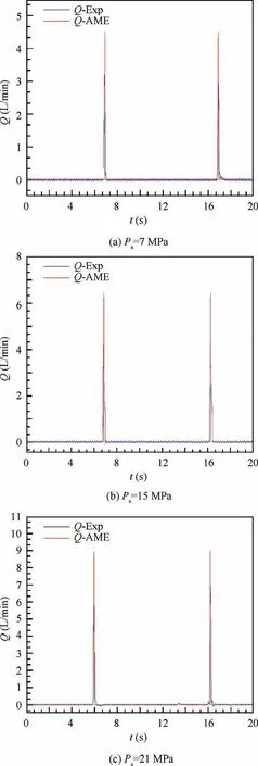
Fig. 18 Leakage flow rate characteristics.

Table 5 Summary of experimental and simulated results of static characteristics.

Table 6 Comparison between 2D maglev valve and traditional 2D valve.
6. Conclusions
(1) A novel configuration of 2D maglev servo proportional cartridge valve is presented where a contactless maglev coupling is introduced between EMC and valve body to realize force transmission, spool position feedback and linear-rotary motion conversion. The experimental results show that the prototype valve can reach a flow rate of 105.9 L/min with hysteresis of 3.5% and a frequency response of 28.7 Hz under pressure drop of 21 MPa. The static and dynamic performance reach the requirements of aircraft electro-hydraulic system,indicating that 2D maglev valve can be a potential solution of flow rate control valve for flight control surface system of civil aircraft with high pressure and large flow rate application.
(2) The working stability criterion is deduced using linear theory. The relationship between crucial parameters and working stability are established. With this criterion, the crucial parameters are chosen and the prototype valve is designed. Experiments prove that the prototype valve is an over-damped system, which has excellent working stability.
(3) The 2D maglev valve can be regarded as a mechanicalhydraulic closed-loop control system.Numerical simulation reveals that some crucial parameters including supply pressure initial height of overlapping area width of high-pressure and low-pressure holes, pitch angle of maglev coupling have great influence on valve dynamic response,while the length of sensitive chamber has little impact.
(4) The simulation results are in good agreement with the experimental results for both static and dynamic characteristics,which indicates the AMESim simulation model can provide reliable theoretical guidance for future valve design.
(5) The application of maglev coupling is not limited to 2D maglev valve proposed in this paper, but of universal meanings.One end of this coupling can relate to various electro-hydraulic valves including flow valve,directional valve,and pressure valve;and the other end can relate to various unidirectional and bidirectional LEMCs such as on-off solenoid,linear force motor,voice coil motor and so on. Besides, future research work should focus on how to further improve the output torque of maglev coupling in order to improve the dynamic response and reduce hysteresis of valve.
Declaration of Competing Interest
The authors declare that they have no known competing financial interests or personal relationships that could have appeared to influence the work reported in this paper.
Acknowledgement
sThis study was co-supported by the National Natural Science Foundation of China (Nos. 51975524 and 51405443) and the National Key Research and Development Program (No.2019YFB2005201)
 CHINESE JOURNAL OF AERONAUTICS2021年4期
- CHINESE JOURNAL OF AERONAUTICS的其它文章
- Time delay compensation in lateral-directional flight control systems at high angles of attack
- Dual stability enhancement mechanisms of axial-slot casing treatment in a high-speed mixed-flow compressor with various tip clearances
- Development cost prediction of general aviation aircraft using combined estimation technique
- Improvement on shaped-hole film cooling effectiveness by integrating upstream sand-dune-shaped ramps
- Modeling and parameter identification of linear time-varying systems based on adaptive chirplet transform under random excitation
- An experimental method to obtain the hard alpha anomaly distribution for titanium alloy aeroengine disks
