Comprehensive sizing and optimization method for series-hybrid unmanned convertiplane
Gang CHEN, Dongli MA, Yuhong JIA, Xinglu XIA, Cheng HE
School of Aeronautic Science and Engineering, Beihang University, Beijing 100083, China
KEYWORDS Aircraft optimal design;Convertiplane;Hybrid electric system;Unmanned aerial vehicle;Vertical takeoff and landing
Abstract This paper presents a novel sizing and optimization approach for the emerging serieshybrid unmanned convertiplane, which can be used to translate the top-level design requirements into the design parameters corresponding to the optimal power supply strategy and minimum total takeoff weight. The method comprehensively considers the design constraints in the rotor, fixedwing, and transition modes, and pays special attention to the characteristic response of Series Hybrid Electric System(S-HES)in complex application scenarios,especially the coupling of battery power, energy, and state-of-charge under high-power discharge conditions, the variation of fuel economy, and the adjustment of power supply strategy. With proposed method, it’s possible to rapidly explore the design space in the initial design stage and find out the optimal design results with high confidence.A case study was proposed to verify the approach.The results reveal the particularity of convertiplane in terms of power requirements, and prove the necessity to consider detailed S-HES characteristic responses during parameter determination. The optimal design parameters were obtained through the hybrid control parameter optimization, which verified the effectiveness of proposed method.Possible errors and corresponding correction methods were also presented.
1. Introduction
Unmanned convertiplane is a new type of aircraft that combines the advantages of multirotor and fixed-wing aircraft.This type of aircraft can cope with complex application scenarios due to its high cruising efficiency,fast cruising speed,and Vertical Takeoff and Landing (VTOL) capability, which has recently become a research hotspot in the Unmanned Aerial Vehicle (UAV) field. There are many convertiplanes currently under development, such as GL-10,Songbird,Panther,Quantix,etc. Most of them are powered by pure electric systems. Constrained by the energy density of current batteries,the endurance of pure electric UAVs is very limited.One of the most effective ways to improve the endurance without changing the outside powertrain layout is to update the pure electric system into a Series Hybrid Electric System (S-HES).Instead of employing the battery as the only power source,S-HES is equipped with a new Main Power Unit (MPU)consisting of an internal combustion engine,a generator,and a Power Management System (PMS), while the battery only functions as an auxiliary power unit to meet the high-power demand.
Benefiting from fuel’s high energy density,the introduction of S-HES provides the possibility of greatly improving the endurance without causing a significant increase in total takeoff mass, but in the meantime, the mass and energy consumption introduced by S-HES itself also have a great impact on the aircraft design result.In the initial aircraft design stage,the sizing process is an important process that translates the design requirements into major aircraft parameters(e.g.wing loading,wing area, total mass, fuel mass, powertrain mass, etc.).Affected by the complex flight profile and powertrain characteristics,the sizing process of the series-hybrid unmanned convertiplane is significantly different from that applied in traditional fixed-wing or multirotor UAV cases. To obtain the optimal design parameters at the early design stage,the sizing approach of series-hybrid unmanned convertiplane should not only cope with the complex flight profile, but also be able to deal with the impact of the design freedom brought by SHES on the parameter determination. Meanwhile, the special response of S-HES components under complex conditions(such as the coupling of battery power, energy, state-ofcharge under high-power discharge conditions, the impact of engine operating point on the fuel economy) also strongly affects the final result.
However,there is little information available on such a sizing method. The existing studies of the impact of hybrid electric system on the sizing method mainly focus on the fixedwing UAV field, among which Finger et al. used series and parallel hybrid electric systems to extend the traditional design space of fixed-wing UAV,Reynard et al.studied the impact of different hybrid electric systems on the sizing of an aircraft with distributed propulsion,Friedrich et al. analyzed the influence of hybrid electric system on fixed-wing UAV under different index systems,while Hoogreef et al. conducted a concept evaluation of hybrid electric fixed-wing aircraft equipped with distributed propulsion and turbocharging.There are also some studies focused on the operation strategy of HES equipped on fixed-wing UAVs. These studies are aimed at reducing the aircraft’s fuel consumption or emission levels, thus in turn affecting the determination of overall parameters. Among them, Donateo and Spedicato used the ON-OFF operation strategy to improve the fuel economy of hybrid electric fixed-wing aircraft.Hoelzen et al. analyzed the coupling between the operation strategy of regional hybrid electric aircraft and COemissions.In addition to the research based on the current technical level and having short-term achievability, there are also some forward-looking works on the design of hybrid electric fixed-wing aircraft,such as the LEAPtech program with distributed hybrid propulsionand the PEGASUS concept applied for regional aircraft.
These studies are very constructive, but they cannot be directly extended to series-hybrid unmanned convertiplanes due to the huge differences in application scenario and design requirements.There are also some inspiring studies on the sizing process of unmanned convertiplanes,which discussed the energy and power requirements in detail, but are all based on pure-electric systems.
Compensating for this lack of existing literature,this paper presents a novel sizing and optimization method for the serieshybrid unmanned convertiplane. The method borrowed elements from the typical preliminary design technique studied and implemented for traditional fixed-wing UAV, but introduced multiple new functional modules to consider the complex application conditions of unmanned convertiplane, the special response of S-HES under these conditions, and the impact of S-HES on the overall parameter determination.With proposed method, it is possible to rapidly explore the design space of series-hybrid unmanned convertiplane,to evaluate the impact of different power supply strategies on the sizing result, and to determine the size, mass, and power parameters corresponding to the optimal design that fully exploits the S-HES benefits. Detailed implementation of this method was described from a theoretical perspective in Section 2. After that, a case study was presented in Section 3, in which the method was applied for the sizing and optimization of a series-hybrid unmanned convertiplane that performs 12-h endurance flight, which verified the method’s effectiveness.
2. Method description
The sizing and optimization method presented in this section is a general approach that can be used to translate the design requirements of series-hybrid unmanned convertiplane into its optimal design parameters.The method consists of multiple functional modules, including multi-mode constraint analysis,hybrid electric power solving, cell-based battery sizing,Willans-line-based fuel consumption analysis, other mass calculation and overall parameter iteration, and hybrid control parameter optimization.
2.1. Multi-mode constraint analysis
Unmanned convertiplanes cover a variety of configurations from tilt-wing,tilt-rotor,composite-wing,to the tail-sitter configuration. Configurations of these aircraft are quite different,but their application scenarios and power requirements are similar, so their sizing process can be uniformly described.The common flight modes of unmanned convertiplanes include rotor mode,fixed-wing mode,and transition mode(see Fig.1,using tilt-wing convertiplane as an example).Operating conditions and design constraints are totally different in these modes.Therefore, constraint analysis is required in each flight mode to obtain the wing loading and power loading that meet performance requirements.
2.1.1. Constraint analysis in fixed-wing mode
Typical fixed-wing flight conditions of convertiplane include cruise/endurance flight,climb,ceiling flight,maximum velocity flight, etc. Under these conditions, the constraint relationship between the wing loading (W/S) and power loading (P/W)can be uniformly described using the following formula:


Fig. 1 Flight modes of unmanned convertiplanes.
where W represents the total takeoff mass, S the wing reference area,P the power absorbed by propellers/rotors,β is fuel weight consumption factor, q the dynamic pressure, Cthe zero-lift drag coefficient. K=1/(πe·AR) represents the induced drag coefficient where AR is wing aspect ratio, e the Oswald’s coefficient.h is flight altitude, dh/dt is the rate of climb, V the velocity, ηthe propeller efficiency. In the initial design stage without detailed aerodynamic characteristic, the zero-lift drag coefficient Cand Oswald’s span efficiency coefficient e are estimated based on the conventional data of the similar UAV type, where Cis between 0.028 and 0.035,and e between 0.65 and 0.72.The rate of climb dh/dt is equal to zero during cruise/endurance flight and calculated by the following equation during constant speed climb:

where ρ represents the air density,Cand Crepresent the lift coefficient and drag coefficient, respectively.
Benefiting from the additional VTOL power system, convertiplane is free from the restrictions on takeoff distance and landing distance, but designers still needs to consider the stall constraint when selecting parameters. For tilt-wing, tiltrotor, and composite configurations, the stall speed mainly affects the power consumption in transition mode, while for the tail-sitter configuration, the stall speed also affects the height increase during the transition. Therefore, the stall constraint is required to be included in fixed-wing constraint analysis,i.e.,W/S ≤qC,where qis the dynamic pressure in stall state and Cthe maximum lift coefficient.
All the above constraints constitute a feasible region for the design of unmanned convertiplane in fixed-wing mode.Within the feasible region,the wing loading and power loading can be selected according to the size, mass, and power requirements.
2.1.2. Constraint analysis in rotor mode
Typical rotor-mode flight conditions of convertiplane include hovering, vertical ascent, vertical descent, etc. Power constraints under these conditions can be uniformly described based on the momentum theory:
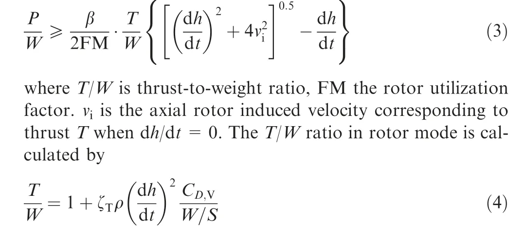
where Cis the rotor-mode drag coefficient, ζis the flight status factor(hovering:ζ=0;vertical ascent:ζ=1;vertical descent: ζ=-1). The rotor utilization factor FM=0.4742(T/N), where Nis the rotor number.The axial rotor induced velocity vis equal to (T/(2ρNS)), where Sis the single disk area which is related to wing span b and wing reference area S through rotor geometric factor γ:

2.1.3. Constraint analysis in transition mode
Flight conditions in transition mode are complex, but the duration is short. The power loading in this mode is closely related to the aircraft’s configuration, transition trajectory,and flight attitude.Under ideal conditions, the power required for transitional flight is only slightly higher(and in some cases even lower) than the rotor-mode power load.However,in the actual design process,to reduce the transition time, expand the transition corridor and provide a buffer for non-ideal conditions, it is necessary to reserve a greater power margin for the convertiplane in transition mode. In the initial design stage with little information available on the specific transition trajectory, this power margin can be equivalently described using the maximum take-off thrust-to-weight ratio(T/W). The larger the value of (T/W), the greater the power margin, thus leading to shorter duration and better safety. Typical values of (T/W)is between 1.15 and 1.5.According to this, the transition-mode power constraint can be expressed as follows:

2.2. Hybrid electric power solving
The power system equipped on series-hybrid unmanned convertiplane is shown in Fig. 2 (taking tilt-wing convertiplane as an example).This system consists of propellers,rotors,electric drives, auxiliary power battery, and a Main Power Unit(MPU) including an engine, a generator, and a Power Management System (PMS).
The operating states of S-HES are distinct in each flight mode to cope with different power requirements, as shown in Fig.3.The MPU works in all modes,while the battery only assists power supply in the high-power rotor mode and transition mode.Meanwhile,an additional battery charging mode is set to charge the battery with the remaining power of MPU during fixed-wing cruise/endurance.
The power transfer path of S-HES is shown in Fig. 4. This path contains two power requirements, namely the payload supply power P, and the total propeller/rotor absorbed power Pwhich corresponds to the power loading obtained from constraint analysis. It also contains four internal operating power items, including the engine output power P, generator output power P, battery charging/discharging power P, and the total electric drive power demand P. In Fig. 4, the four unknown power items are marked with an asterisk on the right for clarity.
In each flight mode,the unknown internal operating power is translated from the known power requirements using a hybrid power equation set. This hybrid power equation set contains three power transfer equations and one power supply control equation. The power transfer equations describe the power transfer process of the generator, PMS, and electric drives, while the power supply control equation describes the power allocation scheme between MPU and battery. The two types of equations together form the hybrid power equation set as follows:

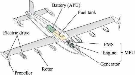
Fig. 2 Structure of S-HES equipped in series-hybrid unmanned convertiplane.
where η, η, and ηare the power transfer efficiency of PMS, generator, and electric drives, respectively. Φ=P/(P+P) is the battery degree of hybridization, indicating the ratio of battery charging/discharging power to the total SHES power load, which is positive when discharging and negative when charging.The theoretical value range of the battery degree of hybridization in the non-charged state is 0%-100%,in which Φ=0% corresponds to the MPU-only state,Φ=100% corresponds to the pure-electric state, and Φ∈(0%,100%) represents the hybrid state. The operating status of S-HES varies greatly in different flight modes, and the Φ value varies consequently (see Table 1).
The transition-mode power load described in Eq.(6)corresponds to the maximum power state of S-HES. The battery degree of hybridization in this mode can be freely selected between 0% and 100%, which is a key control parameter that determines the S-HES power supply scheme and recorded as hybrid control parameter Φ. In fixed-wing mode, only the MPU operates, so the battery degree of hybridization Φis zero. In rotor mode, the battery serves as an auxiliary power supply and its operating power is determined by the MPU remaining power. The battery degree of hybridization in this mode is recorded as Φ. The charging mode occurs during a fixed-wing cruise. The charging power is determined by the MPU remaining power and the battery maximum allowable charging power. The battery degree of hybridization is recorded as Φ.The values of Φand Φare calculated by

where Pis maximum generator power.Pand Pare the operating power of generator and electric drives in fixed-wing cruise/endurance flight,respectively.Pis battery maximum allowable charging power. Pis the total propeller/rotor absorbed power in rotor mode.
When the hybrid control parameter Φis given,by solving the hybrid power equation set in transition mode and fixedwing mode, the operating power of each S-HES component in the two flight modes can be obtained, and the maximum power of each component can be derived accordingly. Since engine characteristics are closely related to the altitude,before solving the maximum engine power, the conversion of operating power to sea-level power needs to be completed with the following formula:
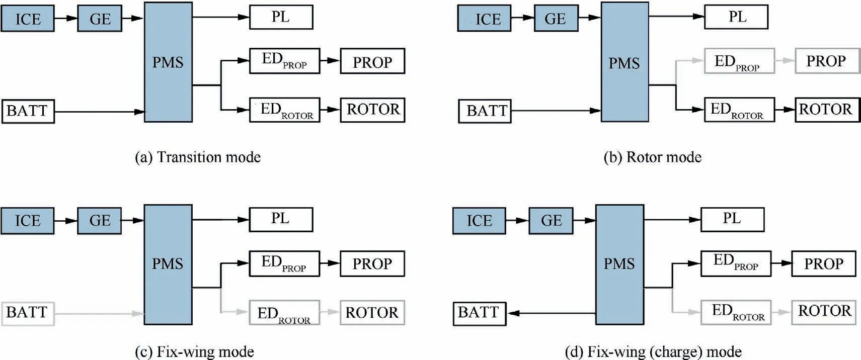
Fig. 3 Operating states of S-HES in different flight modes (ICE: Internal combustion engine; GE: Generator; BATT: Battery; PL:Payload; ED: Electric drive; PROP: Propeller).

Fig. 4 Power transfer path of S-HES. Power values unknown are marked with asterisks.

Table 1 Operating mode of S-HES and corresponding battery degree of hybridization Φ.

where Hand H are the sea level altitude and the current flight altitude, respectively. Pis the standard atmospheric pressure at sea level, and Pis that at the current flight altitude. Tand Tare the corresponding standard atmospheric temperatures.On this basis, the unknown battery degree of hybridization Φand Φcan be calculated, so as to obtain the operating power values of each S-HES component in all flight states.
2.3. Cell-based battery sizing
The battery mass in series-hybrid unmanned convertiplane has a large proportion of the total take-off mass. Therefore, its high confidence estimation has an important influence on the overall parameter determination in the initial design stage.Compared with the batteries used in traditional fixed-wing UAVs, the batteries equipped in series-hybrid unmanned convertiplanes have a much shorter discharge time, and higher continuous discharge power and peak discharge power.Therefore,during the battery mass calculation,it is necessary to consider the attenuation of battery available energy (or capacity)caused by the increase of continuous discharge power(or continuous discharge current), i.e., the Peukert’s effect.Meanwhile, the impact of the battery state-of-charge on the peak discharge power also needs to be considered.
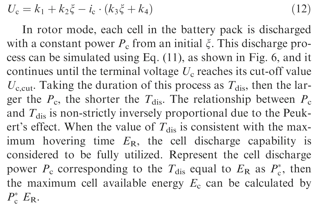
In the overall parameter determination stage, detailed battery pack parameters are not available,so it is difficult to evaluate battery performance directly at the battery pack level.Therefore, the small-capacity cell inside the battery pack can be used as the basic performance evaluation unit. Taking an 18,650 cell widely used in the assembly of power batteries as an example (see Table 2 for its parameters), the variation of the its terminal voltage Uwith the discharge time t during the constant power discharge has the following form:

where Pis cell discharge power, ξ represents cell state-ofcharge, k, k, k, kare cell characteristic parameters. The form of k-kis different under different complexity.The constant k-kcan be used to describe the linear section of the discharge process,while the k-kas functions of state-of-charge ξ can also take into account the non-linear characteristics in the discharge curve (especially in the low ξ range). This research adopts the latter form. The values of k-kwere identified using Eq. (12) at each ξ according to the discharge curves tested at constant current i.The comparison of the test curves and simulation curves shown in Fig. 5 proves the advantage of this method.
In transition mode, the cells in the battery pack are discharged for a short time (several seconds) at peak power P. The value of Pis closely related to the cell state of charge ξ,as shown in Eq. (13). As ξ decreases, Pdecreases accordingly. To ensure flight safety and also to fully exploit cell’s peak discharge capacity and avoid the excessive battery weight, the peak discharge is only allowed when ξ ∈[50%, 100%], and the Pcorresponding to ξ=50% is taken as the design value of peak discharge power to participate in the battery mass calculation.

Table 2 Parameters of an 18650 lithium-ion cell.
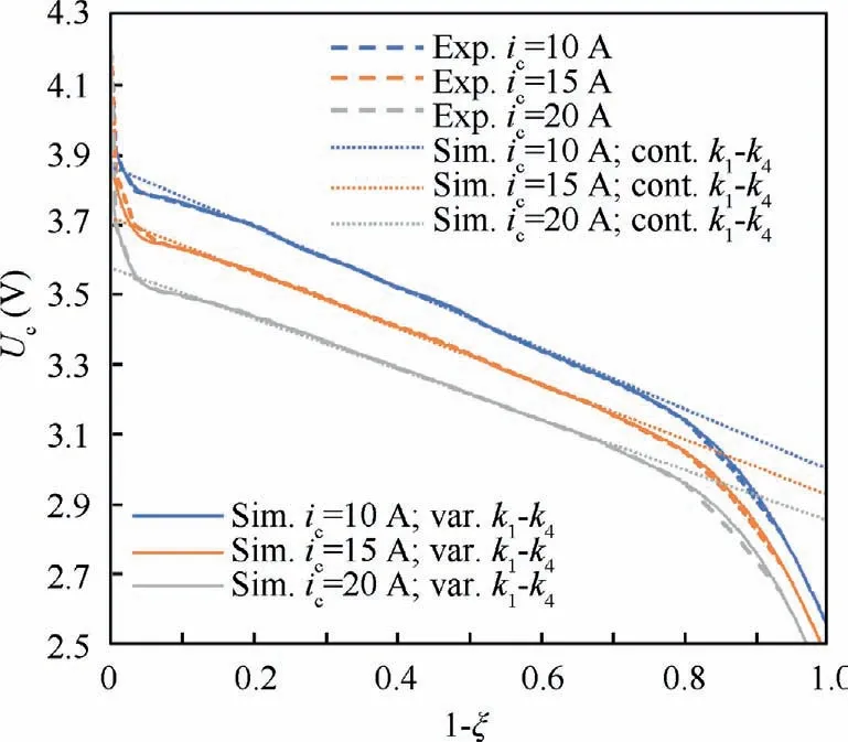
Fig. 5 Comparison of test curves at constant discharge current and the simulation results obtained using Eq. (12) (k1-k4 are constant or as functions of ξ).
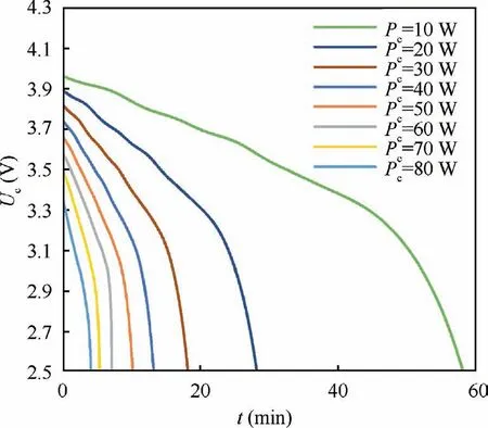
Fig. 6 Constant power discharge simulation results.
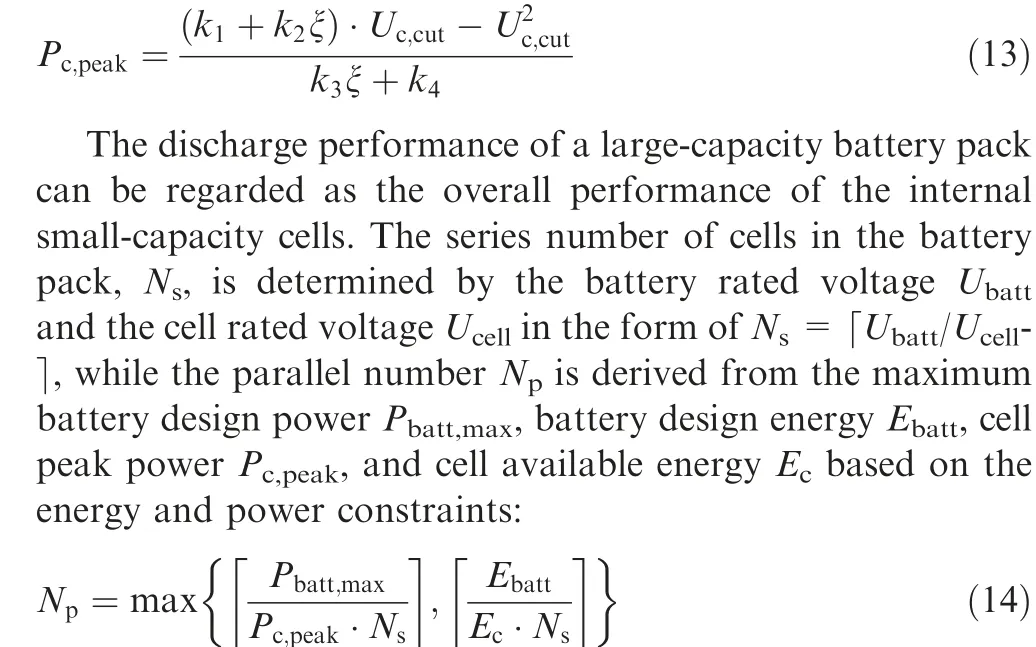
where the battery design energy Eis equal to the product of the battery power in hovering state(P)and the maximum hovering time in rotor mode (E). From this, the cell-based battery sizing equation can be obtained as follows:

where Mis the mass of a single cell, ζ is the mass increase factor introduced by battery pack control, connection circuit,and packaging, with a value of 1.2.Substituting the cell performance evaluation result into Eq.(15),cell series and parallel numbers and the overall battery pack mass can be obtained on the premise of comprehensively considering the impact of complex application conditions of series-hybrid unmanned convertiplane on the actual battery performance.
2.4. Willans-line-based fuel consumption analysis
Fuel consumption analysis is used to convert the top-level design requirements such as endurance, hovering time, and payload power supply into the reserve fuel mass of the convertiplane, which is an important step in the overall parameter determination process. There are significant differences in the operating points of series hybrid unmanned convertiplane under different flight modes, and the difference increases with the decrease of the hybrid control parameter Φ. At different operating points,the fuel consumption of the same engine can be more than doubled.The complete description of engine fuel characteristics depends on the fuel characteristic curve shown in Fig. 7(a), where SFC is the mass of fuel consumed per unit kilowatt-hour energy, i.e.,the unit fuel consumption rate. The example curve is taken from test data of an ignition piston engine with a design power of 95 kW and a displacement of 1.9 L.When determining the overall parameters, the engine maximum power calculated from the hybrid power solving process is in an iterative change,so it cannot be predetermined,which means the fuel characteristic curve is required to be scalable.Pretreatment of the fuel characteristic curve is performed using Willans line method. This method is a widely used and validated quasi-static method for evaluating the performance of unknown scaled-up or -down engines based on the engine data of the same type.This method translates the original characteristic parameters in the reference fuel characteristic curve(such as the engine torque T,fuel consumption per hour ˙m,and engine speed ω)into normalized characteristic parameters including the average effective pressure p, the effective fuel pressure p, and the average piston speed c, and establish the correspondence between p, p,cbased on the law of energy conservation as follows:

where e, e, e, e, e, p, pare the characteristic coefficients determined by multilinear regression using pand pdata from the benchmark engine, which are 0.412,0.0127, -3.26×10, 2.9×10, 7.15×10, 1.82×10,662.6, respectively, for the engine in Fig. 7(a). The displacement Vand stroke length Sof the scaled engine are directly proportional to its maximum design power,and its normalized characteristics parameters p,p,cmeet the same law as the benchmark engine, which is:

Fig. 7 Simulation of engine performance based on Willans line method.

Substituting the characteristic coefficients of the benchmark engine into Eq. (18),the normalized parameter relationship of the scaled engine can be established.Based on the new normalized engine parameters(p,p,c),the fuel consumption curve of the scaled engine can be reconstructed using Eq.(19),where His fuel’s lower heating value, Vthe scaled engine’s displacement,and Sthe stroke.T,ω, ˙mrepresent the scaled engine’s torque, speed, fuel consumption per hour,respectively.Fig.7(b)and Fig.7(c)respectively present the fuel characteristic curve reproduced and scaled using the Willans line method based on the engine characteristic curve in Fig. 7(a). Such engine fuel characteristic curves dynamically generated based on a given maximum design power, provide a data benchmark for evaluating the fuel economy of an unknown engine at different operating points.
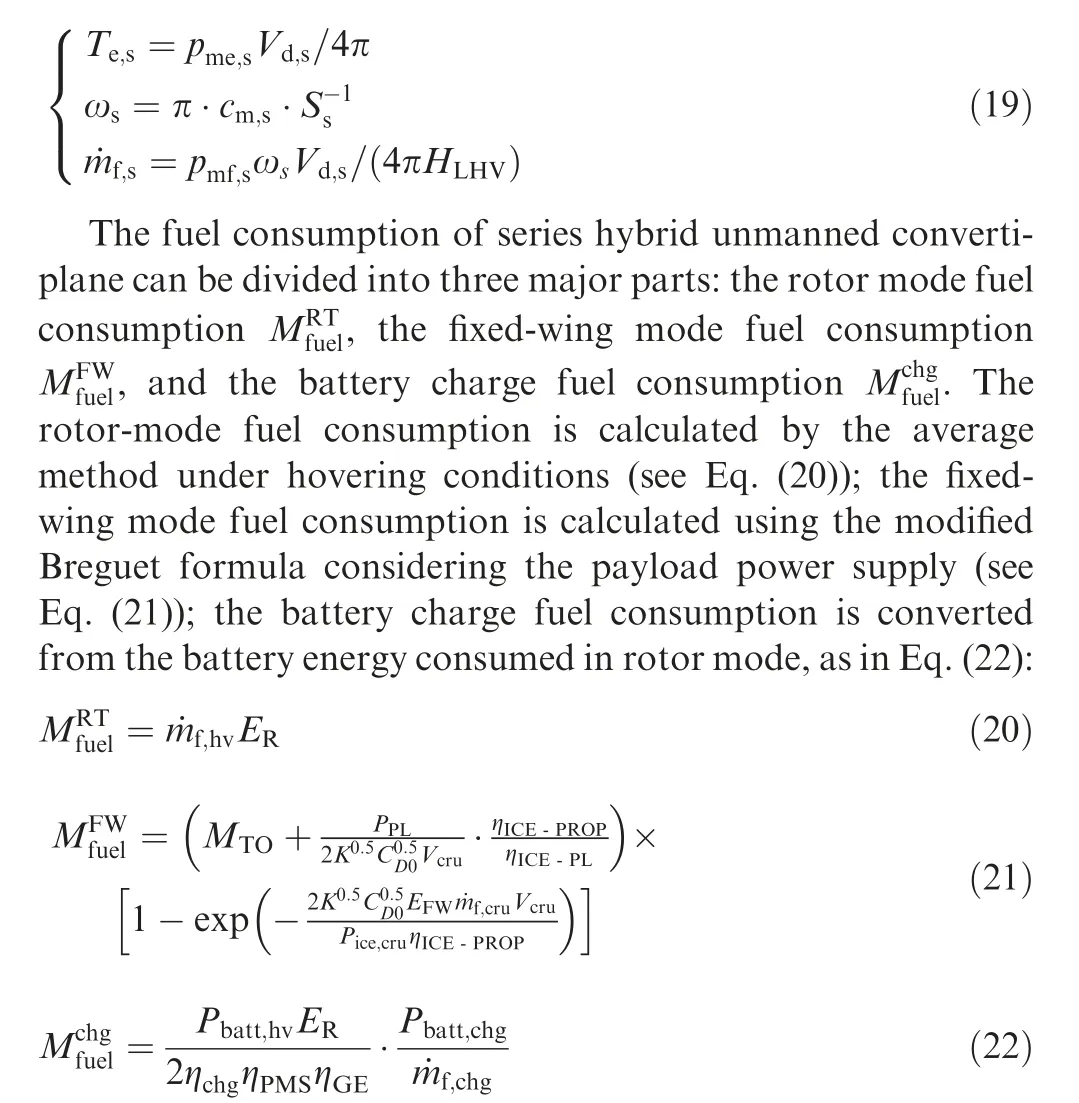
where ηis battery charging efficiency.ηis the power transfer efficiency from engine output to propeller input, and ηfrom engine output to payload input. The values of η-Iand ηare equal to the product of component efficiency on the power transfer path. Vis cruise speed.Pis the engine operating power in cruise state. ˙m,˙m, ˙mare the fuel consumption per hour in hovering,cruising and battery charging states, respectively. To reduce the mass of PMS in S-HES, a stable generator output voltage is preferred,which requires the engine to run around a certain rated speed. This rated speed is determined by the generator rated output voltage and its KV value (N=U/KV),and the values of ˙m, ˙m, ˙mare determined at this speed by interpolation of the fuel consumption curve scaled by the Willans line method.
2.5. Other mass calculation and overall parameter iteration
Different from the battery mass, the mass of other S-HES components(including engine,generator,PMS,electric drives,propellers and rotors) only depends on their maximum design power. Table 3 shows the mass calculation formulas for these components. Among them, the mass calculation equations of engine, generator, and electric drives are established on the power and mass statistics of a large number of existing products with Requal to 0.97, 0.98, 0.97, respectively.An additional modification is also added to the electric drives’mass equation to correct the difference between the electric drives’ actual maximum voltage Uand the reference voltage Uusing the method proposed by Gundlach.The mass of PMS is determined by the design power of internal functional components(such as AC/DC conversion circuit,battery charging circuit, and payload power supply circuit),and its calculation formula is established on the measured data of two actual PMS.The propeller/rotor mass is determined by the method proposed by Roskamaccording to the blade number N, blade diameter D, and electric drive’s maximum design power, P.
In addition to the mass of fuel and S-HES, the total takeoff mass of series-hybrid unmanned convertiplane also includes the structural mass,avionics mass,and payload mass.In the initial design stage, the structural mass factor δ(the ratio of structural mass to the total take-off mass)of convertiplanes is taken as 30%-40%,which is slightly higher than the 25%-30%in fixed-wing UAV casesdue to the introduction of additional power devices and tilt mechanism. The avionics mass factor δis about 5%-8%. The payload mass Mis determined according to the design requirements.From this, the total takeoff mass Mcan be updated by

where Mis the total S-HES mass.Substituting the updated Minto the multi-mode constraint analysis starts a completeiterative calculation of the overall parameters until the parameter converges, as shown in Fig. 8. The output of the iterative overall parameter calculation is the overall design parameters that match the design requirements and the current hybrid power supply scheme,including the total take-off weight,wing loading, power and energy requirements, fuel mass, the mass and the design power of each S-HES component, etc.

Table 3 Mass solving equation of other S-HES components.
2.6. Hybrid control parameter optimization
The overall parameter determination results of series hybrid unmanned convertiplane are closely related to the selection of S-HES power supply strategy, i.e., the selection of hybrid control parameter Φ. As Φincreases, the power supply scheme in transition mode gradually changes from an MPUonly state (Φ=0%) to a battery-only state (Φ=100%).Due to the huge differences in power density, energy density,and operating efficiency between the MPU and the auxiliary battery, the power supply scheme variation will have a significant impact on the overall parameter determination results.In order to obtain the optimal design result which corresponds to the minimum M, it is necessary to optimize the hybrid control parameter Φ. This optimization problem can be analytically expressed as follows:
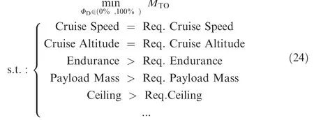
When Φincreases, the variation trend of the convergence iteration result and the variation trend of the single-step calculation result are consistent, so the optimization problem described above can be analyzed first in a single-step run.Without considering the impact of the iterative calculation,the partial derivative of the total take-off mass to Φcan be directly written as:

where M, M, Mare the energy-constrained battery mass, power-constrained battery mass, and the MPU mass, respectively. Δε is the fuel consumption variation as Φchanges, which is negligible compared with the S-HES mass change. Represent the battery energy density, battery power density, and MPU power density as ρ, ρ,and ρ, respectively, then the approximate expressions of M, M, and Mcan be derived from the hybrid power equation set (Eq. (7)) as follows:
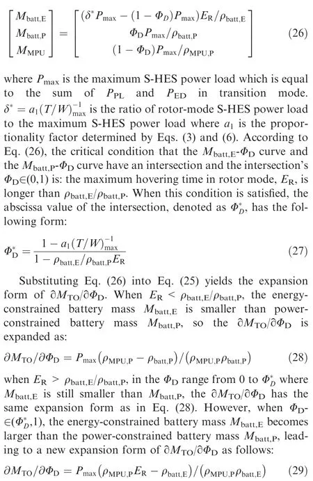
Since ρ<ρ,the ∂M/∂Φin Eq.(28)is always negative, while the ∂M/∂Φin Eq. (29) is positive when E>ρ/ρand negative when E<ρ/ρ.That’s to say, the only condition that M-Φcurve has a pole is that E>ρ/ρ, or otherwise Mwill decrease monotonically with Φ. The coordinates of the optimal design point in the M-Φmap under the two conditions are (Φ, M) and (Φ,M), respectively,where the Φis the maximum Φin the allowable range.
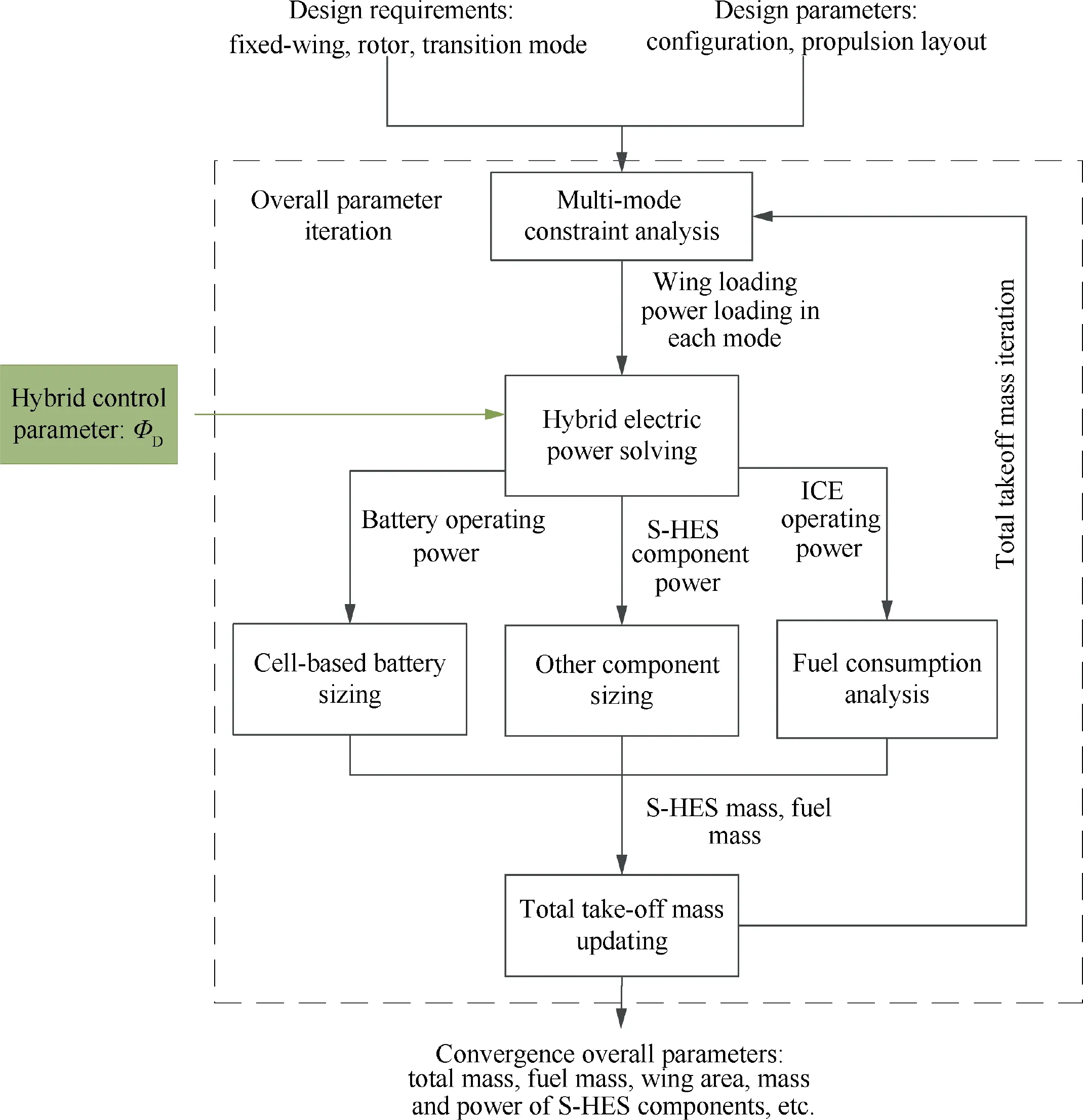
Fig. 8 Flowchart of overall parameter iteration.
This analysis shows that for series hybrid unmanned convertiplane, there is a critical maximum hovering time determined by the characteristics of MPU and auxiliary battery(i.e., E=ρ/ρ). When E<E, the optimal Φis always at high levels; when E>E, the optimal Φis located at the intersection of the M-Φcurve and the M-Φcurve, and its value is jointly determined by the maximum hovering time E, maximum take-off T/W ratio(T/W), and battery power and energy characteristics (Eq.(27)).
The complete optimization of hybrid control parameter Φalso needs to consider the fixed-wing mode power limitation,fuel economy variation, the impact of discharge condition on the battery performance, etc. Therefore, simplified analytical expressions as mentioned above are not enough. Instead, a more comprehensive solving process is employed, as shown in Fig.9.The hybrid control parameter Φis set by the design of experiment or the gradient descent optimization method,and the overall parameter iterative process illustrated in Fig. 8 is embedded in the optimization process as the key solver. Based on this method, the influence of hybrid control parameter Φon the overall parameters can be captured under the comprehensive consideration of the foregoing factors. It eliminates the subjectivity of Φselection, and thus can be used to find the optimal design solution with the lightest mass that meets all the design requirements at the initial design stage.The overall parameters of the optimal design point(such as the total takeoff weight, wing loading, power and energy requirements, fuel mass, mass and design power of each SHES component,etc.)are taken as the final results of the sizing and optimization of the series-hybrid unmanned convertiplane, which will serve as the necessary design inputs for the further convertiplane design procedures such as detailed aerodynamic optimization, equipment selection, or other subsystem design.
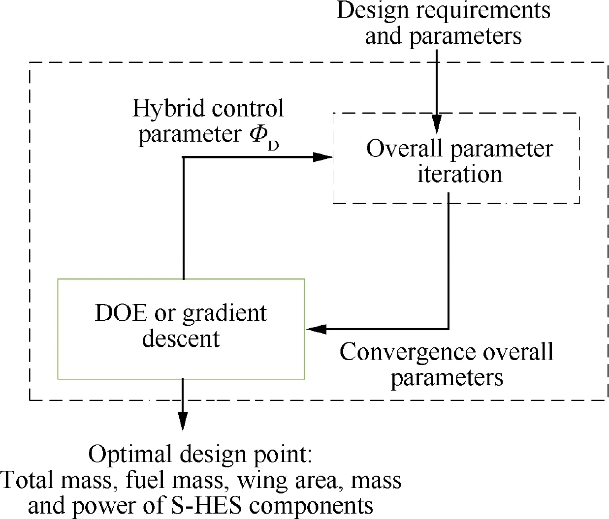
Fig.9 Process of hybrid electric control parameter optimization.
3. Case study
In this section, a series-hybrid unmanned convertiplane performing a 12-hour endurance flight mission was taken as an example to verify the sizing and optimization method described in the previous section. Sensitivity analysis was carried out based on that.Possible errors and corresponding correction methods were also introduced.
3.1. Aircraft configuration and design requirements
The series-hybrid unmanned convertiplane studied herein adopts the tilt-wing configuration with distributed propulsion(see Fig. 1). It equips two sets of fixed-wing propellers and eight sets of lift rotors. The maximum design payload is 20 kg, the cruising altitude is 3 km, and the endurance time is 12 h. The complete mission profile is shown in Fig. 10.Table 4 lists the detailed aircraft design requirements. Other known parameters and efficiency assumptions are listed in Table 5.
3.2. Sizing and optimization
In the sizing and optimization process, the gradient descent method may greatly reduce the number of calculation samples and improve the optimization efficiency. However, to clearly show the impact of S-HES on the aircraft design process, in this case study, full factor sampling was performed on hybrid control parameter Φin the entire design space at intervals of ΔΦ=1%.
The wing loading and power loading of the series hybrid unmanned convertiplane are determined by the performance requirements and do not change with Φ(see Fig. 11). To improve the cruise efficiency and obtain a compact airframe structure, the optimal design point in fixed-wing mode is set at the intersection of the stall limit line and the climb limit line,leading to an optimal value of wing loading of 47.5 kg/m.The power requirements under fixed-wing mode, rotor mode, and transition mode are significantly different (see Fig. 11(b),where Ris the ratio of S-HES output power to its maximum design power). The continuous power required for the 12-h endurance flight is only 9% of S-HES maximum design power, while for traditional fixed-wing or multi-rotor UAV,the ratio of continuous power to maximum power is usually 40%-60%. The power demand disparity of the series hybrid unmanned convertiplane is the key to taking the S-HES advantages.
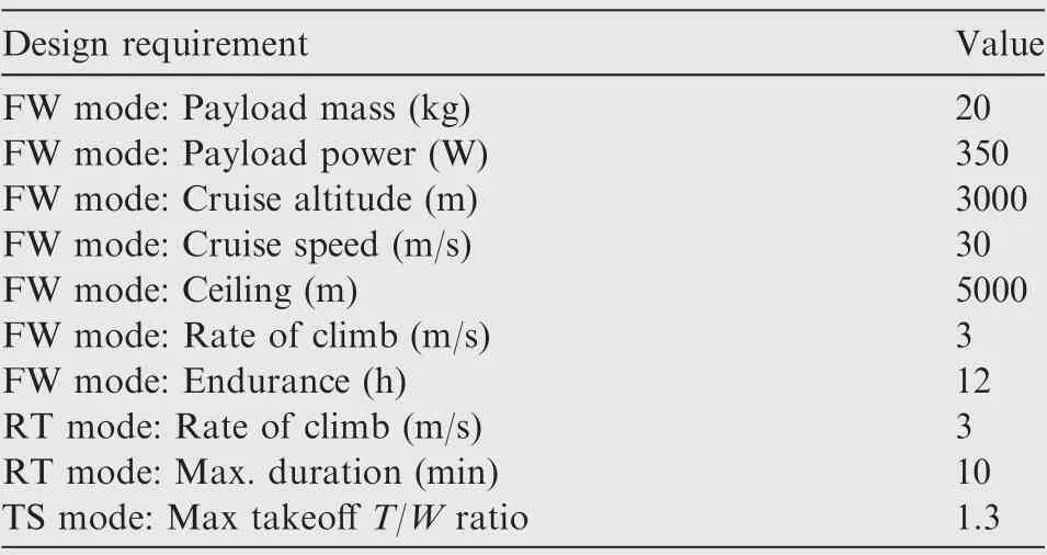
Table 4 Design requirements of series-hybrid unmanned convertiplane. (FW: Fix-wing; RT: Rotor; TS: Transition).
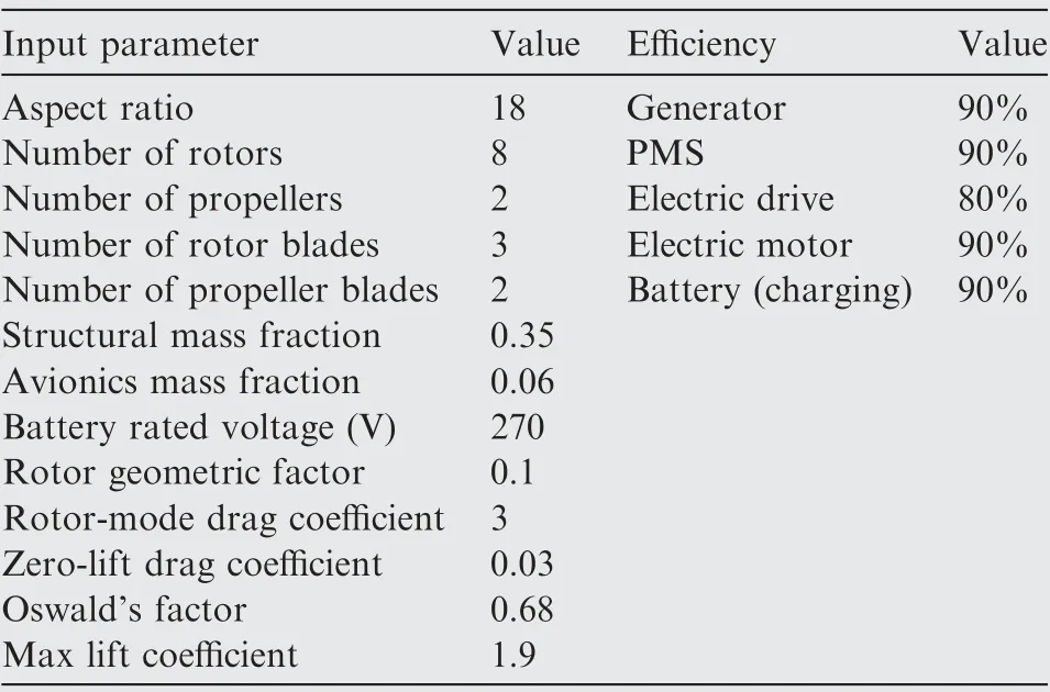
Table 5 Input parameters and some efficiency assumptions.
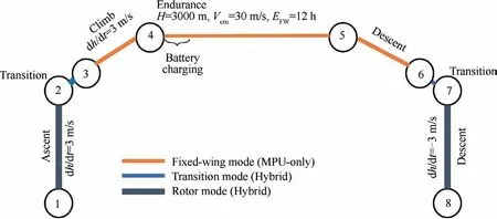
Fig. 10 Flight profile of series-hybrid unmanned convertiplane.
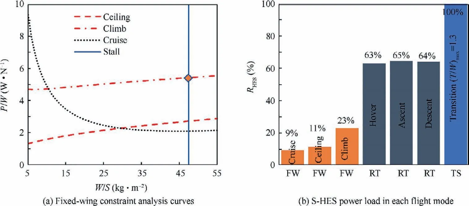
Fig. 11 Multi-mode constraint analysis results.
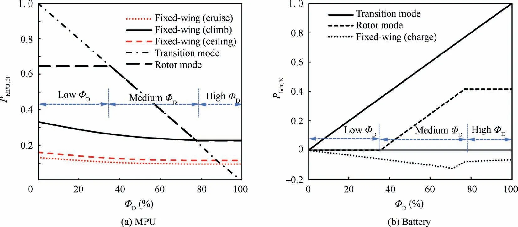
Fig.12 Normalized MPU and auxiliary battery operating power,i.e.the ratio of operating power to the maximum S-HES power load.
Fig. 12 shows the S-HES power supply strategies corresponding to the different hybrid control parameter Φ. To facilitate the comparison of various states, both MPU output power Pand battery power Pare normalized as the proportion of S-HES maximum power load and recorded as Pand P.As Φincreases,the power supply scheme variation can be divided into three phases: low, medium and high battery degree of hybridization phases.In the low battery degree of hybridization range (Φ∈(0,36%)), the MPU can independently meet the power requirements in fixed-wing and rotor mode, while the battery only participates in short-term power supply during transition flight; in the medium battery degree of hybridization stage (Φ∈(36%,79%)), the MPU power drops below the rotor-mode power demand,so the battery begins to participate in both rotor mode and transition mode; in the high battery degree of hybridization stage(Φ∈(79%,100%)), the MPU power is only enough to meet the fixed-wing power demand,while the battery becomes dominant in rotor mode and transition mode. The power supply strategy variation affects the overall parameters from multiple aspects, as shown in Table 6.
In the low battery degree of hybridization range,cell’s number and the total battery pack mass are constrained by the maximum power and rated voltage demand. Only when Φreaches the medium and high battery degree of hybridization phases, the battery energy demand (i.e. maximum hovering time) becomes a new battery sizing constraint.
Along with the battery constraint changes is the change in the overall S-HES characteristics. The difference between MPU and battery in terms of energy density and power density is particularly evident in the special application scenario of convertiplanes. Fig. 13(a) shows the correspondence between the continuous discharge duration T, cell continuous power P, and battery energy density ρobtained from the cell performance assessment. Short-time high-power discharge greatly reduces battery available energy: the battery energy density at T=5 min is only 64% of that at T=30 min.The decrease of battery power density ρcaused by the decrease of battery state of charge ξ is also significant (seeFig.13(b)):the battery power density at ξ=30%is only 61%of that at ξ=90%. At the design state-of-charge (ξ=50%),the battery power density is 1516 W/kg.In MPU,the effective energy density of the energy storage element (fuel) is about 2835 Wh/kg (taking the fuel lower heating value as 43,070 kJ/kg, engine combustion efficiency as 30%, generator and PMS efficiency as 90%), which is 27.8 times the battery energy density. In the meantime, the total power density of the power conversion elements(engine,generator,energy management system, see Table 3) is about 580 W/kg, which only accounts for 38% of the battery power density. Therefore,the S-HES with lower battery degree of hybridization has an advantage in energy density,while the S-HES with higher battery degree of hybridization has an advantage in power density.

Table 6 Characteristic of S-HES in different ΦD ranges.

Fig. 13 Variation of battery characteristics.
The difference between the maximum power demand and the continuous power demand of convertiplane is much greater than that of a conventional aircraft, so the impact of Φchange on the fuel economy is much more significant. Represent the ratio of the MPU operating power in fixed-wing cruise state to the MPU maximum design power as MPU operating power ratio R. In the low and medium battery degree of hybridization phases, the Rincreases with the increase of Φ(Φ=20%, R=15%; Φ=79%, R=50%).Fig. 14 shows the SFC of engines at different power levels(5 kW-50 kW) calculated by the Willans line method at R=15% and R=50% (denoted as SFCand SFC,respectively). The fuel economy improvement (ΔSFC/SFC)caused by the Rincrease all exceeds 30% despite the difference in the baseline SFC.Therefore,the closer to the high battery degree of hybridization phase,the better the fuel economy and the less fuel the convertiplane needs to carry.
The influence of hybrid control parameter variation on the design parameters is integrated and amplified during the iteration calculation process,eventually producing the convergence result shown in Fig.15. The optimal design point corresponding to the minimum total take-off mass is obtained at Φ=79%. At this point, the battery in S-HES is employed to meet 79% of the transition-mode power demand and 65%of the rotor-mode power demand, while the MPU provides 21% of the transition-mode power, 35% of the rotor-mode power, and all fixed-wing mode power. In the meantime, the battery is charged at 3.89 kW in the fixed-wing endurance state.The design power of S-HES components and their operating power in each flight mode are listed in Table 7(the engine power is the actual operating power, and no altitude conversion has been performed). The results show that no single power unit is able to independently cope with the special power requirements under the complex operating conditions. Only when the MPU and the battery are well-matched can their respective advantages be maximized. The table also shows the huge difference in the total electric drives’ power requirements under different operating conditions, which is one of the reasons why more and more convertiplanes use distributed propulsion.
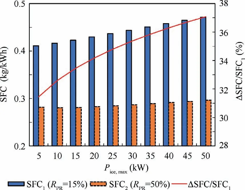
Fig. 14 SFC at RPR=15% and RPR=50% for engines of different rated power, and fuel economy improvement (engine speed fixed at 5000 r/min).
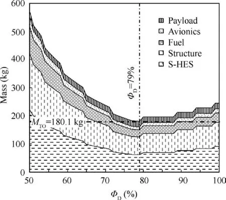
Fig. 15 Mass parameters as functions of ΦD.

Table 7 Sizing results: Operating power of S-HES components. (Unit: kW).
The optimal series-hybrid unmanned convertiplane adopting the above power supply strategies has a total take-off mass of 180.12 kg and a wingspan of 8.25 m. Based on an 11.3 kW MPU,a 40.5 kW battery(N:75;N:6),and 25.2 kg fuel,this convertiplane can complete 12-hour fixed-wing endurance flight carrying a payload of 20 kg while satisfying a maximum take-off thrust-to-weight ratio of 1.3 and a maximum hovering time of 10 min.The main dimensions and mass parameters are listed in Table 8. At this point, the sizing and optimization of this aircraft have been completed.
3.3. Sensitivity analysis
Sensitivity analysis is conducted to discuss the impact of rotormode and transition-mode performance on the optimal hybrid control parameter, total takeoff weight, and fuel economy,thereby further revealing the design rules of series-hybrid unmanned convertiplane.
Fig. 16 shows the variation of the optimal hybrid control parameter with hovering time Eand maximum take-off thrust-to-weight ratio (T/W). The result is consistent with the analytical description in Section 2.6. The critical hovering time Edetermined by S-HES characteristics divides the design space into two parts:
when E<E,MPU is only used to meet the maximum power demand in fixed-wing mode,while the extra power required in rotor mode and transition mode is supplemented by the battery pack, so the optimal Φtends to locate in the high battery degree of hybridizationrange. However, when E>E, the disadvantage of battery in terms of energy density begins to appear. The MPU power proportion is required to be increased to reduce the battery’s energy storage burden. The optimal Φis determined by the intersection of the battery energy constraint line and the power constraint line(see Eq.(27)),and decreases with increasing Eand decreasing (T/W).
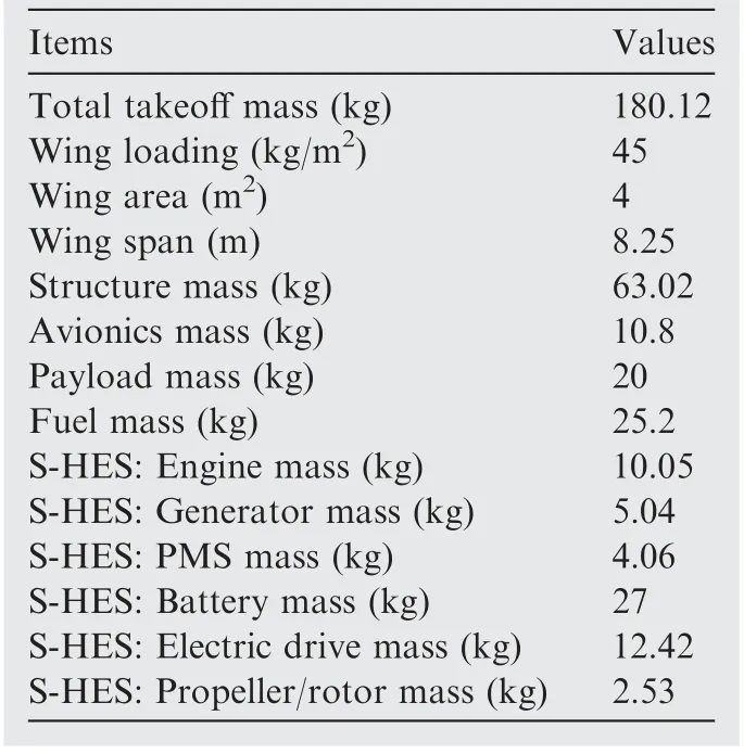
Table 8 Sizing results of the optimal design point.
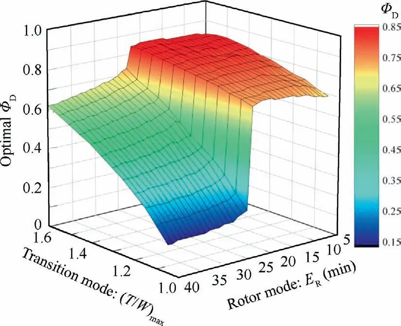
Fig.16 Sensitivity analysis results:optimal ΦD with different ER and (T/W)max.
In the two parts of the design space, the variation laws of minimum Mas functions of Eand (T/W)are totally different (see Fig. 17). In the part where E<E, there is an optimal performance curve in the design space (dotted line in Fig. 17(a)). When the design point is above the curve, the energy demand place stricter constraints on the battery pack than the power demand. The battery is designed to meet the energy demand, but in a power-excessive state. Therefore,the total takeoff mass Mis greatly affected by hovering time E,but is little affected by(T/W).Rules below the curve is just the opposite. When proposing the performance requirements, the maximum hovering time Eand the maximum takeoff thrust-to-weight ratio (T/W)are better to be matched to avoid any power-excess (design points above the dashed line) or energy-excess (design points below the dashed line)battery states.However,when E>E,things are different(see Fig.17(b)).In this range,the optimal Φis taken from the intersection of the M-Φcurve and the M-Φcurve, so the battery energy constraint and power constraint have natural consistency. Therefore, if E>E, the correlation between Eand (T/W)can be ignored when setting the design requirements.
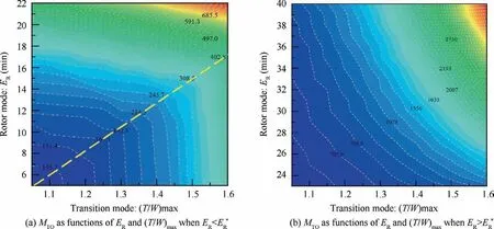
Fig. 17 Sensitivity analysis results: minimum MTO with different ER and (T/W)max.
The design coupling of different flight modes is also reflected in the fuel economy variation. The fuel economy in fixed-wing mode is closely related to the maximum hovering time Ein rotor mode and the (T/W)corresponding to transition mode (see Fig. 18). When E<E, the effect of using the auxiliary battery to improve the fixed-wing mode fuel economy is very obvious: the SFC can be kept low regardless of the values of Eand (T/W). However, when E>E,affected by the engine power increase, the battery’s contribution to the fuel economy improvement in fixed-wing mode is greatly reduced. Taking (T/W)=1.3 as an example, the value of SFC when E=30 min has increased by 32% compared to the SFC value when E=10 min. The deterioration in SFC means an increase in the fuel reserve, which has a strong impact on the final overall parameters. Therefore, it’s very important to consider the coupling effects of different flight modes in the parameter optimization process of serieshybrid unmanned convertiplane.
3.4. Error analysis and correction method
The method proposed in this research is a direct approach that transforms design requirements into overall parameters.Design requirements participate in the complete iterative calculation process as a necessary input, so the consistency between calculation results and performance requirements can be guaranteed. To improve the fidelity of the method,the physical models used are either based on experimental and test data, or have been widely used or verified; the statistical models used are established on large amounts of existing products, not on the expectations of any technological development. However, in actual use, the residual between the statistical prediction and the actual value is inevitable for each individual sample. This residual error is the main source of error between the parameters predicted using the proposed method and the parameters of the actually manufactured aircraft. To reduce this error, a list of alternative S-HES components can be set according to the power calculation results listed in Table 7,and actual lookup tables based on the actual S-HES component data can be created to replace the statistical formulas shown in Table 3, thereby further increasing the accuracy of the overall parameter optimization results.
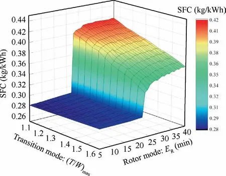
Fig.18 Sensitivity analysis:engine SFC in fixed-wing mode with different ER and (T/W)max.
4. Conclusions
(1) The series hybrid unmanned convertiplane has some particularities in terms of the power demand:the continuous power required for the fixed-wing endurance flight only accounts for 9% of the maximum design power,which is much lower than the 40%-60% for traditional aircraft.
(2) The performance of S-HES is strongly affected by the actual application scenario of series hybrid unmanned convertiplane. The battery power, energy, and state-ofcharge are greatly coupled in high-power rotor mode and transition mode, and the fuel economy is determined by the engine operating point in fixed-wing mode.According to the results of cell-based battery sizing process and Willans-line-based fuel consumption analysis,the battery energy attenuation caused by high discharge power and the peak power attenuation caused by the reduced state-of-charge both exceed 35%, while an increase in engine operating ratio from 15% to 50%improves fuel economy by more than 30%. Thus, considering the S-HES characteristic response in the actual application scenario is very important during parameter determination.
(3) The power supply strategy of S-HES is determined by the hybrid control parameter input. The optimal power supply strategy should fully exploit the benefit of S-HES in terms of power,energy,and fuel economy,and lead to the optimal design results with minimum total take-off weight. When the hovering time is less than a critical value determined by S-HES characteristics, the optimal hybrid control parameter is determined by the power demand in transition mode and fixed-wing mode;otherwise, the optimal hybrid control parameter is determined by the hovering time in rotor mode and the maximum take-off thrust-to-weight ratio in transition mode. The design results in the two cases are also completely different in terms of the fuel economy improvement brought by the auxiliary battery and the coupling degree of design requirements in multiple modes.
(4) With the overall parameter iterative process as the key solver, the hybrid control parameter optimization can output the optimal design results on the premise of comprehensively considering the S-HES characteristic response and power supply strategy changes. The main error of this method comes from the residuals between the predicted and actual values brought by statistical formulas. Replacing these formulas with actual lookup tables can greatly reduce the error.
Declaration of Competing Interest
The authors declare that they have no known competing financial interests or personal relationships that could have appeared to influence the work reported in this paper.
 CHINESE JOURNAL OF AERONAUTICS2021年4期
- CHINESE JOURNAL OF AERONAUTICS的其它文章
- Time delay compensation in lateral-directional flight control systems at high angles of attack
- Dual stability enhancement mechanisms of axial-slot casing treatment in a high-speed mixed-flow compressor with various tip clearances
- Development cost prediction of general aviation aircraft using combined estimation technique
- Improvement on shaped-hole film cooling effectiveness by integrating upstream sand-dune-shaped ramps
- Modeling and parameter identification of linear time-varying systems based on adaptive chirplet transform under random excitation
- An experimental method to obtain the hard alpha anomaly distribution for titanium alloy aeroengine disks
