Hot-cracking susceptibility and shear fracture behavior of dissimilar Ti6Al4V/AA6060 alloys in pulsed Nd:YAG laser welding
Xin XUE, Xinyong WU, Jun LIAO,*
a School of Mechanical Engineering and Automation, Fuzhou University, Fuzhou 350116, China
b Fujian Nebula Electronics Co., Ltd., Fuzhou 350015, China
KEYWORDS Aluminum alloy;Hot-cracking susceptibility;Pulsed Nd:YAG laser welding;Shear fracture behavior;Titanium alloy
Abstract Laser welding of dissimilar titanium/aluminum alloys has been employed at an increasing rate, particularly in the aerospace industry, owing to its advantages in terms of current design flexibility and fuel/cost savings.The major problem with dissimilar Ti/Al welds arises from the difference in the thermal expansion and contraction of the two metals, which leads to hot-cracking susceptibility and the mitigation of the mechanical property after welding. In the present study,pulsed Nd:YAG laser welding of Ti6Al4V and AA6060 has been addressed. Hot-cracking susceptibility in the heat affected zone and the shear fracture behavior of the lap joints were investigated through microstructural characterization and mechanical tests. The results indicate that the hot cracking tendency can be reduced by increasing the pulse peak power (7.5-8.5 kW) and the laser point diameter (0.8-1.0 mm)with specific pulse duration and overlap.An alternative control strategy for less hot cracks in the Ti/Al lap joint can be to increase the weld width and decrease the cooling rate during solidification. The shear fracture of the Ti/Al lap joint is likely to occur along the lower side path of the weld interface with decreasing weld surface collapsed amount and increasing aluminum base metal melt depth.
1. Introduction
Dissimilar metal welding is attracting increasing attention in various fields, owing to its ability to take advantage of the specific attributes of each material to enhance the performance of the final product or to introduce novel functionalities. For instance,the dissimilar Ti/Al structures have already been used in the wings of the airplanes (see Fig. 1), where the titanium alloy crust and the aluminum alloy honeycomb are welded together.As an implication, there is a requirement of a method that utilizes the superior properties of dissimilar materials, such as the corrosive properties and strength of Ti and the lightweight and low cost of Al.Although considerable research has been devoted to the same, and the similar metal welding techniques currently available offer suitable material and mechanical properties,rather less attention has been paid to dissimilar lightweight metal welding and to the undesirable weld quality of thin plates.

Fig. 1 Laser welding structure of titanium alloy crust and aluminum alloy honeycomb.
In recent years,certain processing technologies such as laser welding,diffusion welding,brazing welding,and friction stir welding (FSW),have been employed in an attempt to join dissimilar titanium and aluminum alloys.Laser welding exhibits certain some advantages, which include low heat input, low thermal deformation, high automation, mass production efficiency, and low pollution.Pulsed Nd:YAG laser welding,in particular,is used widely for joining dissimilar alloys with a high melting point, owing to the advantages of short welding cycle, wide adjustment range, and high energy input accuracy offered by this welding technique.However, the huge difference in the physical and chemical properties between the titanium alloy and the aluminum alloy results in a series of problems, including the initiation of cracks and the lower joint strength caused by the formation of brittle intermetallic compounds (IMCs), such as Ti3Al, TiAl, TiAl2 and TiAl3.Although considerable efforts have been put to laser welding of dissimilar titanium and aluminum alloys,rather less attention has been paid to the issue of hotcracking susceptibility (HCS) and the mechanical strength of the weld joint.
Efforts and explorations concerning the reduction in the initiation of joint cracks and improvement in the joint strength in the laser welding of the dissimilar Ti/Al alloys have been made in previous studied. For instance, Wang et al.used laser-MIG hybrid welding-brazing without grooves to successfully butt-weld the AA6061 aluminum alloy to the Ti6Al4V titanium alloy. Lei et al.reported that a suitable Ti/Al butt joint formed through laser brazing could be obtained by using the additive coaxial Al-10Si-Mg powders approach.Lv et al.indicated that dissimilar alloys of Ti6Al4V and 5A06 Al could be butt joined through keyhole arc welding-brazing using Albased fillers. This method prevented the formation of the IMCs, which enable obtaining a sound Ti/Al joint. Similarly,it was often attempted to join the dissimilar Ti/Al alloys by using a third metal to form an interlayer. Majumdar et al.observed that the formation of the IMCs could be avoided by inserting the Nb foil, which resulted in a crack-free Ti/Al joint. Song et al.used electron beam welding to join Ti60 to GH3128 with a Cu interlayer. The above-stated research works are focused mainly on how to prevent the formation of the IMCs in the laser welding of dissimilar Ti/Al alloys,and attention is rarely focused on the influence of the welding process parameters on the cracks appearing in the Ti/Al joints.
One barrier encountered in the dissimilar Ti/Al welding is the inherent characteristics of the aluminum alloy, such as low absorption rate of the laser beam, large linear expansion coefficient, large solidification shrinkage, a large number of low-boiling elements and the conveniently formed lowmelting eutectic.In addition, rapid heating and cooling processes of the laser welding lead to a large number of hot cracks in the aluminum alloy during the laser welding process.Hekmatjou and Naffakh-Moosavyobserved that the hot-cracking tendency of the aluminum alloy could be reduced by using a pulsed laser in the pre-heating stage.Radel and Woizeschkeindicated that the hot-cracking susceptibility of the aluminum alloy during the laser welding process could be reduced by using the vibration-assisted method.Abbaschian and Limainvestigated the influence of the laser parameters on the hot-cracking susceptibility during the welding process of the aluminum alloy. Aluminum alloys are particularly prone to hot cracking initiation during laser welding when there is no use of filler materials or a third metal as the intermediate layer. Zhang et al.studied the effects of the process parameters on the hot- cracking sensitivity of the laser overlap welded AA5754 and AA6013 sheets in terms of preventing or reducing the initiation of hot cracking.Xue et al.reported that hot cracks were also observed at the interface of the dissimilar Ti6Al4V/AA6060 alloy laser-welded lap joint.The problem of hot-cracking initiation in dissimilar laser welding has always been a challenge. Zero or less number of hot cracks in a dissimilar welded joint is vital for lightweight manufacture as they represent enhanced strength of the joint.Therefore,further analysis of the effects of the process parameters on the HCS of the Ti/Al joints in laser welding is necessary.
Of particular interest is the fact that the Ti/Al broken joints present different shear fracture paths after the tensile shear test. This phenomenon is associated with the weld geometry size,which encourages the study of the shear fracture behavior of the Ti/Al joints.Vaidya et al.indicated that different laser offsets could affect the location of the fusion-welded Ti/Al joint and the distribution of the IMCs, while the tensile strength and the fracture path also changed significantly as a result.The relationship between the structure of the IMCs layers and the tensile strength of the Ti/Al joints was discussed by Zhang et al.All these authors highlighted the influence of the Ti/Al IMCs layer structure on the strength of the Ti/Al welded joint;however,they neglected the weld pool geometry.In fact,the weld geometry also affects the distribution of the IMCs layer, and therefore, the weld pool geometry is also a crucial parameter for the mechanical strength of a Ti/Al joint.
The present study aims to explore the effects of the pulse welding process parameters on hot-cracking susceptibility in the heat-affected zone and the shear fracture behavior of the dissimilar Ti6Al4V/AA6060 lap joints in pulsed Nd:YAG laser welding. An alternative control strategy for a smaller number of hot cracks in the Ti/Al lap joint is studied through microstructure characterization and experimental design. In addition, the formation mechanism and the source of hot cracks are analyzed,and the distribution evolution of the interfacial phase compositions is determined.
2. Materials and methods
2.1. Materials used
In the present study, commercial Ti6Al4V and AA6060 alloys were selected as the base metals for the pulsed Nd:YAG laser welding. The chemical compositions of the two base materials as received have been listed in Table 1.
2.2. Pulsed Nd:YAG laser welding
The SISMA SWA300 pulsed laser welding machine(Fig.2)at the University of Aveiro in Portugal was employed for the welding experimental test. In order to avoid sample sliding induced by the laser shock, the samples required proper fixing with a particular clamping fixture. High-purity (99.9%) argon inactive gas was passed through the bottom and top surfaces at a flow rate of 12 L/min during the laser welding process. The whole welding process was conducted in an argon-filled environment to prevent the molten pool and the heat-affected zone(HAZ) from being oxidized. The distance between the laser exit and the top surface of the sample was set to 105 mm with the best resolution.
Owing to the high reflectivity of the aluminum alloy surface to the laser,the titanium plate was fixed on the top of the aluminum plate. This implies that there is a lap joint for the dissimilar Ti/Al weld. The two laying solutions for the studied dissimilar Ti/Al welding samples have been illustrated in Fig. 3. One sample overlap solution was used to analyze the influence of the welding parameters on the HCS of the dissimilar Ti/Al joints.The other symmetrical lap welding model was utilized for the tensile shear test.
After a series of ‘‘trial and error” experimental welding tests,it was determined that the potential parameter configuration with a pulse peak power percentage in the range of 80%-95% the duration of 8-10 ms, the overlap of 50%-70%, and the laser point diameter of 0.8-1 mm would be appropriate for the dissimilar laser welding under study.In order to further investigate the influence of the welding process parameters on the hot-cracking susceptibility and shear fracture behavior of the dissimilar Ti/Al joints, the experimental scheme was divided into two groups: A and B. The single factor welding experimental scheme (see Table 2) was used to analyze the HCS of group A, while the orthogonal experimental test L9_4_3 (see Table 3) of the group B was designed according to the suitable sets of welding parameters.
2.3. Microstructural characterization
Prior to welding, all the samples were cleaned with acetone,and the oxide layer on the surface of the Ti/Al plates was polished using wire brush. Subsequently, all the samples were soaked in 30%HNO3 solution for approximately 3 min.Since the samples were irregular-shaped and not conveniently observable after the welding process, they were excised into suitable size using a diamond wire cutting machine, and the cross-section position of all the samples perpendicular to the welding direction was 2.5±0.5 mm from the welding start position. After excising the sample, polish papers of 600#-2500#were utilized to wet grind the sample from coarse to fine texture.The samples were polished on a metallographic polishing machine with 2.5 μm diamond paste and a non-adhesive polishing cloth until ground to 2500#.Finally,after polishing,the samples were cleaned using an ultrasonic cleaning machine and dried under cold air.
A tungsten scanning electron microscope of Quanta 250 type was employed to observe the morphology of the joint weld at the cross-section as well as at the surface. The HCS of the joints with different pulse parameters was calculated using the Outcad auxiliary software. One of the samples exhibiting obvious hot-cracking characteristics was subjected to energy dispersive spectroscopy (EDS) and multi-functional X-ray diffraction (XRD) test. The source of the hot-cracking formation was explored by analyzing the changes in the composition at HAZ as well as close to the interface.
2.4. Mechanical test
Since there is no standard test for the mechanical test analysis of composite single-lap joints, the GB7124-86 adhesive measurement method (metal to metal) was used to determine the shear strength of the dissimilar Ti/Al lap joints with different pulse parameters. A minimum of three samples from each set of pulse parameters in the L9_4_3 orthogonal plan of group B were subjected to this tensile shear test. All these samples were subjected to pre-heat treatment (413°C, 3 h) prior to the tensile test, and the Shimadzu AG 10 kN tensile test machine (Fig. 4) was employed to perform the tensile shear test.

Table 1 Chemical compositions of Ti6Al4V and AA6060 base materials (wt%).
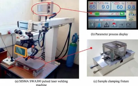
Fig. 2 Pulsed Nd:YAG laser welding experimental apparatus.
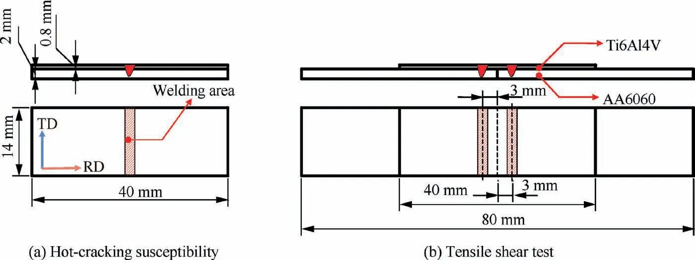
Fig. 3 Two laying solutions for studied dissimilar Ti/Al welding samples.

Table 2 Group A experimental planning for hot-cracking susceptibility analysis.
3. Results and discussions
3.1. Hot-cracking susceptibility
3.1.1. Hot-cracking characteristics
In the Ti/Al pulsed laser welding debugging process, the weld surface generally appears to be extensively oxidized, splashed,molten and burnt. In the present study, the B8 sample exhibited a relatively good surface quality of the weld and obvious hot-cracking characteristics, and was therefore selected for the microscopic observation, the results of which are depicted in Fig.5.It is observed that the cracks were distributed mainly in the center and at the edge side of the weld surface. Therefore, hot-cracking characteristics could be divided into two types.One was the longitudinal crack distributed in the center of the weld, which was deep and long. The other was the arcshaped crack distributed along the edge of the weld,which was short and shallow.In addition,the direction of the arc-shaped crack was perpendicular to the welding wave.

Table 3 L9_4_3 orthogonal experimental planning for group B.
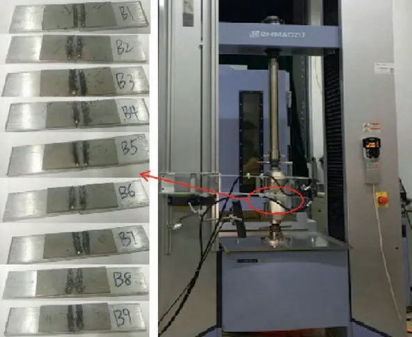
Fig. 4 Shear test samples and tensile testing machine.
3.1.2. Source of hot-cracking formation
As visible in the cross-section morphology of sample B8 in Fig. 6, the weld cracks were located mainly in the center of the weld, for example at the C1 and C2 positions. The results of the EDS analysis of region P1-P3 region have been presented in Table 4. It is clearly observed that the composition of each of these regions(P1-P3)is considerably similar.When studied in combination with the Ti/Al binary phase diagram,it is speculated that the major component of the P1-P3 regions is TiAl, which must have formed mainly as a result the violent reaction between the upper collapsed titanium and the lower aluminum molten pool.
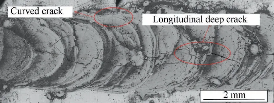
Fig. 5 Weld surface morphology of sample B8 with a peak power percentage of 95%, duration of 9 ms, an overlap of 50%,and a diameter of 1 mm.
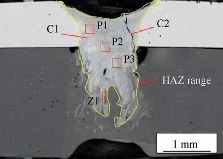
Fig. 6 Weld cross-section morphology of sample B8.
The Z1 region depicted in Fig. 6 was selected for the Ti/Al interface analysis as it was a relatively weak zone prone to hot cracks initiation. Fig. 7(a) presents the magnified view of the Z1 region. The Ti/Al interface region could be divided into four parts: the bright white area, the dark grey area, the saw-tooth shaped area, and the peripheral short bar-shaped area. On the basis of the EDS results obtained for the P4-P9 region which are close to the Ti/Al interface (Table 4), it is inferred that the main component phases of the bright white P4-P5 regions and the dark grey P6 region are TiAl and TiAl2,respectively. The main component phases of the saw-tooth shaped P7 region and the short bar-shaped P8-P9 regions are all TiAl3. Line energy spectrum analysis was performed for position E to F, the results for which have been presented Fig.7(b).The results indicate that the composition of the interface layer is distributed in a high degree order of TiAl, TiAl2,and TiAl3 from the weld to the aluminum base. This reaction order of the Ti/Al interface IMCs can be attributed to the degree of Al element diffusion, the temperature gradient of the interface layer, and the solidification rate. This distributed order of the IMC layer and the saw-tooth shaped interface might be probably responsible for enhancing the connection strength of the Ti/Al interface and reducing the initiation of the hot cracks close to the Ti/Al interface.
Fig. 8 reveals that the presence of TiAl, TiAl2, and TiAl3 IMCs in the weld of the Ti/Al joint detected using the XRD test.Owing to the low plasticity of IMCs at room temperature,several defects such as hot cracks appearing in the Ti/Al joints can be a result of residual stress during solidification.
When the melting pool is in a molten state during the pulsed Nd:YAG laser welding of Ti/Al, the metal in the weld seam could be subjected to pressure stress caused by the unmelted cold aluminum alloy present outside the melting pool.Subsequently,the weld metal would begin to solidify and contract during cooling and crystallization, and the compressive stress would be transformed into tensile stress. Moreover,there are huge differences between the properties of the weld metal components and that of the outside un-melted aluminumalloy. In particular, the large expansion performance of the aluminum alloys intensifies the degree of expansion and contraction. This is related to the size and shape of the melting pool in different directions of the weld, resulting in greater pressure and tensile stress at the center of the Ti/Al weld.The welding-induced IMCs and the residual stress play a considerably significant role in the hot- cracking formation in the Ti/Al joint weld.

Table 4 EDS element distribution for selected locations of P1-P9 depicted in Fig. 6 and Fig. 7(a).
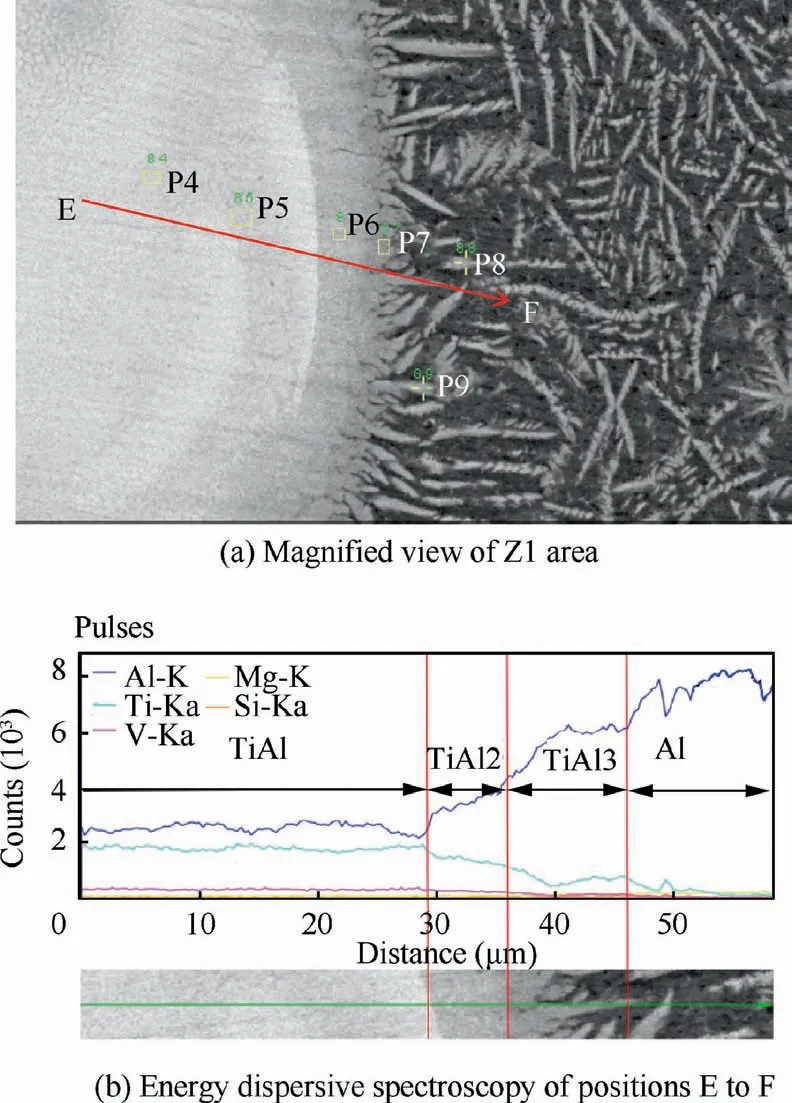
Fig. 7 Microstructure observation of Ti/Al interface.
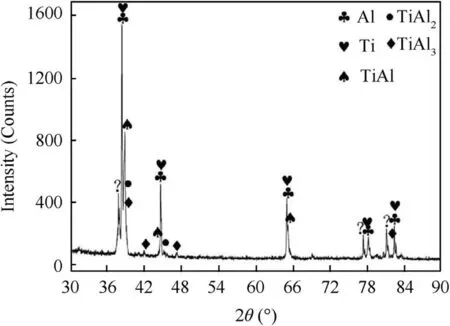
Fig. 8 X-ray diffraction results of Ti/Al lap joint.
3.1.3. Influence of pulsed Nd:YAG laser parameters
Although hot cracks are unavoidable without the use of filler materials or a third metal as the intermediate layer,it is possible to reduce the initiation of the hot cracks to improve the quality of the Ti/Al joints by controlling the welding process parameters.Therefore,it is necessary to investigate the appropriate welding parameters,particularly in the case of dissimilar welding of the titanium and aluminum alloys. Generally, the theorical analysis of process parameters involves three different groups: laser beam properties (wavelength, power, diameter, divergence), material properties (density, thermal conductivity,specific heat,latent heat of melting and vaporization, thickness, joint configuration) and very important interaction parameters (welding speed, focusing element length,focus plane position towards the material surface, shielding gas direction and flow, absorptivity of material surface). Heat Q necessary to melt material mass m is given by the wellknown equation
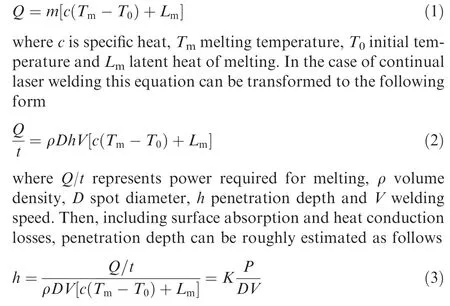
where P is laser power and K constant resulting from material physical characteristics including surface reflectivity and other energy losses. Thus, penetration depth is proportional to the applied laser power and inversely proportional to the spot diameter and welding speed.
Fig.9 illustrates the single factor effect of the pulse welding process parameters on the weld profile of the Ti/Al joints(‘‘P”refers to the pulse peak power percentage. ‘‘Dn” refers to the duration. ‘‘Op” refers to the pulse overlap. ‘‘Dr” refers to the diameter.).The HSC results of group A samples have been presented in Table 5.HCS refers to the ratio of the HAZ total crack area to the weld pool area, and its approximate range is shown in Fig.6.From the macroscopic view,the HAZ range is dependent on the process parameters such as power, laser point diameter and so on. From the microscopic view, the HAZ range is close to the interface of welding pool and about 0.2-0.5 mm.The HAZ hot crack and weld pool areas were calculated using the Outcad auxiliary software. It may be observed that the hot cracks of samples A2, A5, and A9 are present across the whole weld zone. The cracks have deep gaps, and the weld profile is H-shaped. In order to analyze the effects of the pulse parameters on the HCS of the Ti/Al joints, the change in the ratio of HCS with increasing single pulse process parameter has been determined (Fig. 10).
Fig. 10(a) presents the affected trend of HCS of the Ti/Al joints with increasing pulse peak power. The HCS of the Ti/Al joints first increases and subsequently decreases with the elevating peak power, and reaches its maximum value at the pulse peak power percentage of 90%. The reasons underlying this trend could be clarified on the basis of the two stages described ahead. In the rising phase, both laser power density and pulse energy increase as the pulse peak power increases,implying that greater amount of energy would be radiated in the weld area,leading to a higher peak temperature of the weld zone and a greater temperature gradient between the molten pool and its surrounding metal.Another reason is the increase in the depth-to-width ratio of the weld, which directly causes the weld zone to be under larger tensile and compressive stress,resulting in an increase in the joint HCS. In the falling phase,as the pulse peak power continues to increase,a gradual rise in the peak temperature of the weld zone occurs, and the degree of increase in the temperature gradient could be less significant than it was earlier. Meanwhile, the solidification rate would occupy a dominant role for the HCS of the Ti/Al joints. As already known, the rate of solidification and cooling is much slower for a larger melted volume.Obviously,the molten pool areas of samples A1 to A2 exhibited little change, while those of samples A2 to A3 increased from 2.016 to 2.456 mm, as presented in Table 5.Therefore,an increase in the molten pool area causes a reduction in the solidification and cooling rates,and the molten pool would also stay longer in the molten state.In addition,the fluidity of the molten pool would be enhanced in the weld zone with increasing pulse peak power.These phenomena ensure that the residual metal liquid in the weld zone has a greater amount of time to backfill and heal certain places where the weld had cracked during solidification. Therefore,the problem of secondary cracking in the weld zone is avoided,reducing the cracking area of the hot cracks and causing a decline in the HCS.
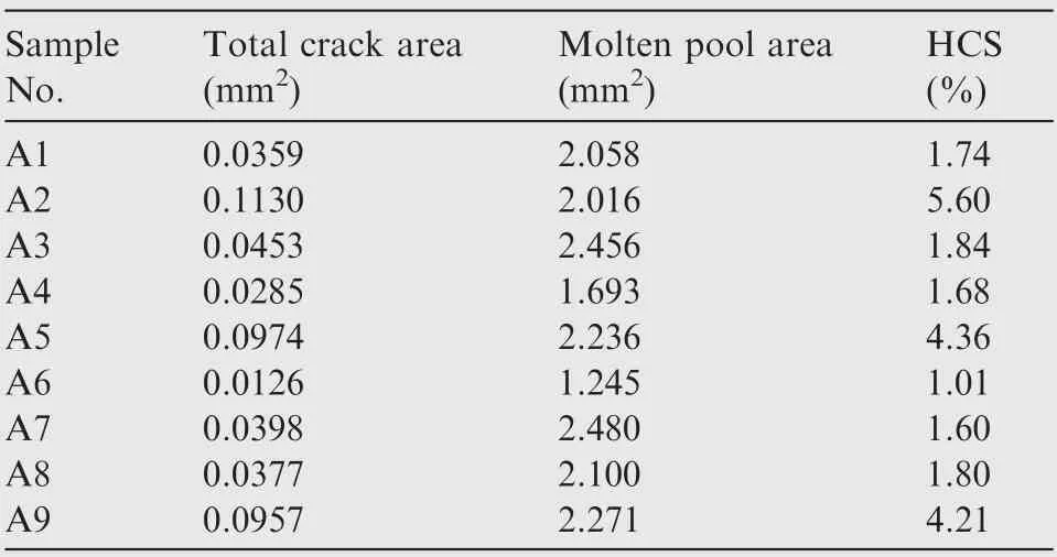
Table 5 HSC results for the samples of group A.
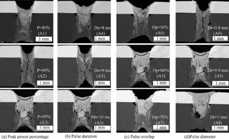
Fig. 9 Influence of pulsed laser welding parameters on weld profile of Ti6Al4V/AA6060 joints at the other three fixed parameters.
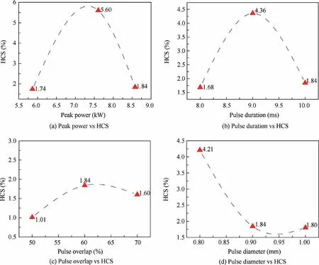
Fig. 10 Change ratio of HAZ total crack area to weld pool area for pulsed Nd:YAG laser welding of Ti6Al4V/AA6060.
Similar to the effect of pulse peak power, the HCS also increases initially and then decreases with the increasing pulse duration,as depicted in Fig.10(b).Pulse duration refers to the process time to reach peak power. The pulse energy and the heating time of the weld zone area exhibit an increase with the rising pulse duration at fixed pulse peak power and other two pulse parameters, which causes a rapid rise of the peak temperature.The peak temperature plays a dominant role during the stage of HCS. It may be observed from Fig. 9(b) that the penetration depth reaches the maximum value, while the melt width exhibits an obvious increase from 9 ms to 10 ms(pulse duration). Consequently, the solidification rate declines due to the increase in the molten pool volume, and the HCS begins declining as well.
It may be observed form Fig. 10(c) that the overall HCS generally exhibits an upward trend with increasing pulse overlap. The overlap is related to the selection of pulse duration,spot diameter,and traverse velocity for a specific mean power.After the trial and error experimental tests, the authors think the suitable overlap should be from 50%to 70%for the studied Ti/Al lap joint by pulsed Nd:YAG laser beam welding. In Fig. 10(c), HCS decreased when the pulse overlap was 70%,because a relatively large pulse overlap leads to an increase of the overlap heating area of the weld surface. This also results in an increase of melting area in the welding pool,especially for the titanium plate joint close to the laser heating source. As for the fluctuation was small, this may be because the selected range of the pulse overlap is narrow. Beyond this range of pulse overlap, the fluctuation should be large but not suitable for the global process optimization in this work. The relation between the welding speed and the pulse parameters may be represented as follows:

where Ois pulse overlap, f is laser frequency or pulse repetition rate, T is pulse duration,and S is the pulse laser spot size on work-piece. It may be observed from Eq. (4) that pulse overlap is an important factor for determining the welding speed, and that the welding speed decreases with a gradual increase in this factor when the other pulse parameters are fixed. Decreasing the welding speed leads to longer heating time and higher peak temperature. This may decelerate the cooling rate of the weld zone and the HCS. Therefore, the pulse overlap of 50%is suitable for the reduction in the HCS.
Fig. 10(d) illustrates that the complete trend of HCS decreases as the pulse diameter increases. Pulse spot diameter serves as a key factor that determines the melt width. It can be observed from Fig. 9(d) that the melt width increases with increasing pulse spot diameter. The molten pool volume also exhibits an increase in a broader perspective. It may be concluded from Eq. (4) that welding speed reduces with the increase of pulse diameter, resulting in a lower cooling rate.This is why HCS tends to rise with increasing diameter in the later stage. Another important factor for the decrease in HCS in dissimilar Ti/Al joints is the depth-width ratio of the weld.Interestingly,it was observed that the samples with high HSC and an H-shaped weld, such as the sample A2, A5, and A9 exhibited a larger depth-width ratio. In comparison, the samples with U-shaped weld had a lower HCS, and their depth-width ratios were also small. Pulse spot diameter is an important factor for increasing the depth-width ratio of the weld, which is achieved by increasing the weld width. Therefore,a relatively large pulse spot diameter within an appropriate range could greatly reduce the HCS and consequently improve the quality of the dissimilar Ti/Al joints.It is noteworthy that the joint with a sufficiently large depth-width ratio could avoid the generation of an H-shaped weld.
One group of optimal pulse process parameters could be obtained through the analysis described above,which included peak power percentage of 95%, pulse duration of 9 ms, overlap of 50%, and pulse spot diameter of 1 mm. As depicted in Fig. 6, the dissimilar Ti/Al joints in this group of welding parameters had less HCS,and their welds were U-shaped with a wide top and a narrow bottom. The peak power percentage of 95% causes the bottom aluminum sheet to be completely penetrable, while the pulse spot diameter of 1 mm ensured a sufficiently large depth-width ratio for the weld.It is clear that the weld geometry is of great significance in regard to the HCS of the dissimilar Ti/Al joints.In addition,a certain relationship exists between the weld geometry and the shear fracture behavior of dissimilar Ti/Al joints, which has been discussed in the following section.
3.2. Shear fracture behavior
It can be found from the above analysis of hot-cracking susceptibility that the weld geometry determines the volume and shape of the molten pool and the HCS of the joint. During laser welding of dissimilar metals, a short and locally focused heat input leads to a degradation of material properties,particularly strength in the heat affected zone of the weld. Thus, a minimization of scrap and rework places high demands on the base material characteristics and the welding process. So far, the loading-path dependence of inter-metallic mechanical behaviours has not yet been examined extensively.For the purpose of evaluating the relationship between the welding process and the inter-metallic mechanical properties of dissimilar metal joints, the tensile-shear experimental test can be performed to determine the joint shear fracture behavior. In this section, the relationship between weld geometry and shear strength, shear fracture path and fracture morphology of dissimilar Ti/Al lap joints with different pulsed laser welding process parameters are analyzed and discussed.
3.2.1. Microscopic geometry of dissimilar Ti/Al joints
Fig. 11 presents the welding geometric parameters and the shear fracture path diagram. The weld surface collapse is a common welding defect. If the weld surface collapsed amount is not controlled strictly, the joint strength would be reduced severely. Similarly, the aluminum base metal melt depth also requires to be controlled within a suitable range, otherwise it may lead to unsoldered,burnt joints,and hot cracks.W refers to the weld interface width of the dissimilar Ti/Al joint.It is an important parameter in weld geometry and also a vital indicator of the shear strength of the joints. According to the GB 7124-86 adhesive measurement standard, the joint shear strength may be calculated as follows:

where Sis the maximum shear strength of the weld joint,Fis the maximum shear fracture load, W is the width of the dissimilar Ti/Al joint weld interface, and L is the length of the Ti/Al joint weld interface after the fracture.
The joint geometric morphology of group B samples has been depicted in Fig. 12. The weld surface collapsed amount h,the aluminum base metal melt depth h,and the weld interface width W of the samples in group B were measured, the results of which have been listed in Table 6.It may be observed that there is a certain relationship between the shear strength of the Ti/Al joints and the weld geometric parameters such as weld surface collapsed amount and aluminum base metal melt depth. In order to analyze the influence of the weld geometric parameters on joint strength, the M value was introduced as a measurement parameter to characterize the combined effect of hand hon the strength of the Ti/Al joint.The specific method of calculation of the M geometric parameter has been provided below

where his the weld surface collapsed amount of the titanium,his the aluminum base metal melt depth,tis the thickness of the titanium base material, and tis the thickness of the aluminum base material.
Fig. 13 illustrates the evolution of the M value and joint shear strength with group B samples. A positive correlation between the M value and the shear strength of the Ti/Al joints was indicated,implying that it is possible to improve the shear strength of the Ti/Al joints by increasing the M value. It is noteworthy that that in dissimilar Ti/Al welding,the weld surface collapsed amount should be reduced, and the aluminum base metal part must have sufficient penetration depth in order to obtain a joint with high shear strength. Although the Ti/Al weld interface is an important indicator of the strength of the joint, it is not sufficiently comprehensive. The M value may also be considered a measurement indicator of the strength of a dissimilar weld.
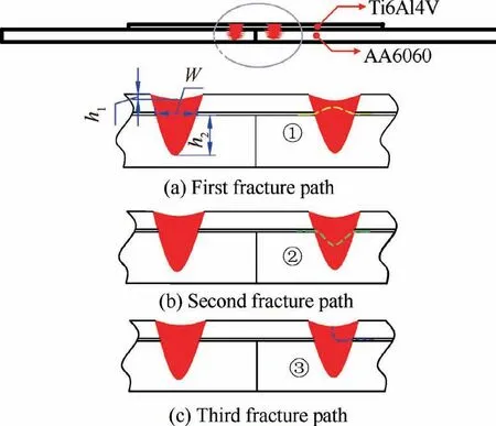
Fig.11 Weld geometric parameters and the diagram of different fracture paths.
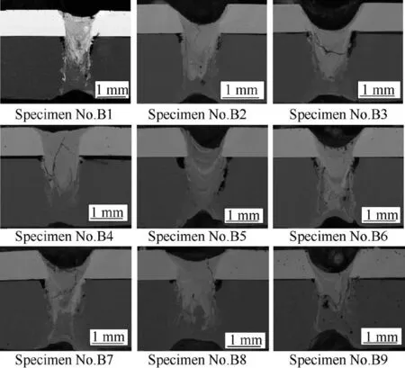
Fig. 12 Joint geometry morphology of specimens in group B.
3.2.2. Path of shear fracture
Fig.11 illustrates the three main kinds of shear paths with different pulse parameters that were observed to occur after the tensile shear test. The first shear fracture path occurs along the upper side of the weld interface. As observable from Table 6, when the weld surface collapsed amount occupies approximately 50%-90% of the titanium base material in the thickness normal direction,the M value is mostly less than 1. In this case, the sample is prone to shear fracture along the upper side path of the weld interface, although its shear strength is relatively small. The second shear fracture path occurs along the lower side of the weld interface. When the weld surface collapsed amount is less than 50%of the titanium base material in the thickness normal direction,the M value is at least greater than 1. In other words, the aluminum base metal melt depth is at least half of the aluminum base material thickness, such that the bottom aluminum sheet is penetrated.In this case, the sample exhibits higher susceptibility to being broken along this shear path, and its shear strength is also the highest among all the samples, reaching approximately 80% of the aluminum base material. The third shear fracture path occurs along the weld center. This path generally occurs when the weld surface collapsed amount is greater than 90%of the titanium base material in the thickness normal direction,and its shear strength is the lowest among all the samples,which is undesirable for dissimilar welding quality.In summary, the second shear fracture path exhibits the highest shear strength among all the samples.The weld surface collapsed amount of the dissimilar joint must be strictly controlled, and not allowed to exceed 50% of the upper titanium base material in the thickness normal direction. In addition,the bottom aluminum base metal should have a melt depth that is at least half of the aluminum base metal thickness so that the sample is completely penetrated.
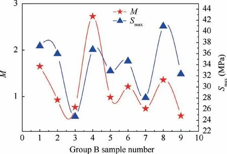
Fig.13 Evolution of M value and maximum shear strength with group B samples.
3.2.3. Fracture morphology
Fig. 14 presents the shear fracture morphologies of samples B3,B4,and B7,and which respectively correspond to the three shear fracture paths described above. It may be observed that the fracture plane of sample B3 is almost smooth and flat,and no dimple appears. This sample is considered to have brittle cleavage fracture. The fracture morphology of sample B4 reveals that most of the regions of this sample are relatively flat and smooth and only a few areas exhibit dimples. Therefore,sample B4 should be having mainly the brittle fracture, with only a few areas exhibiting ductile fractures.In Fig.14(c),sample B7 appears similar to sample B3. The fracture planes of both these samples are flat and smooth, and they may be considered brittle fractures. The fracture morphology along the lower side of the weld interface is different from the other two shear fracture methods. A small number of dimples appeared in the fracture area along the lower side of the weld interface, while the other two fracture methods were brittle cleavage fractures without dimples.This implies that the shear strength of the samples fractured along the lower side of the weld interface is relatively high.

Table 6 Weld geometry parameters and shear fracture strength of specimens in group B.
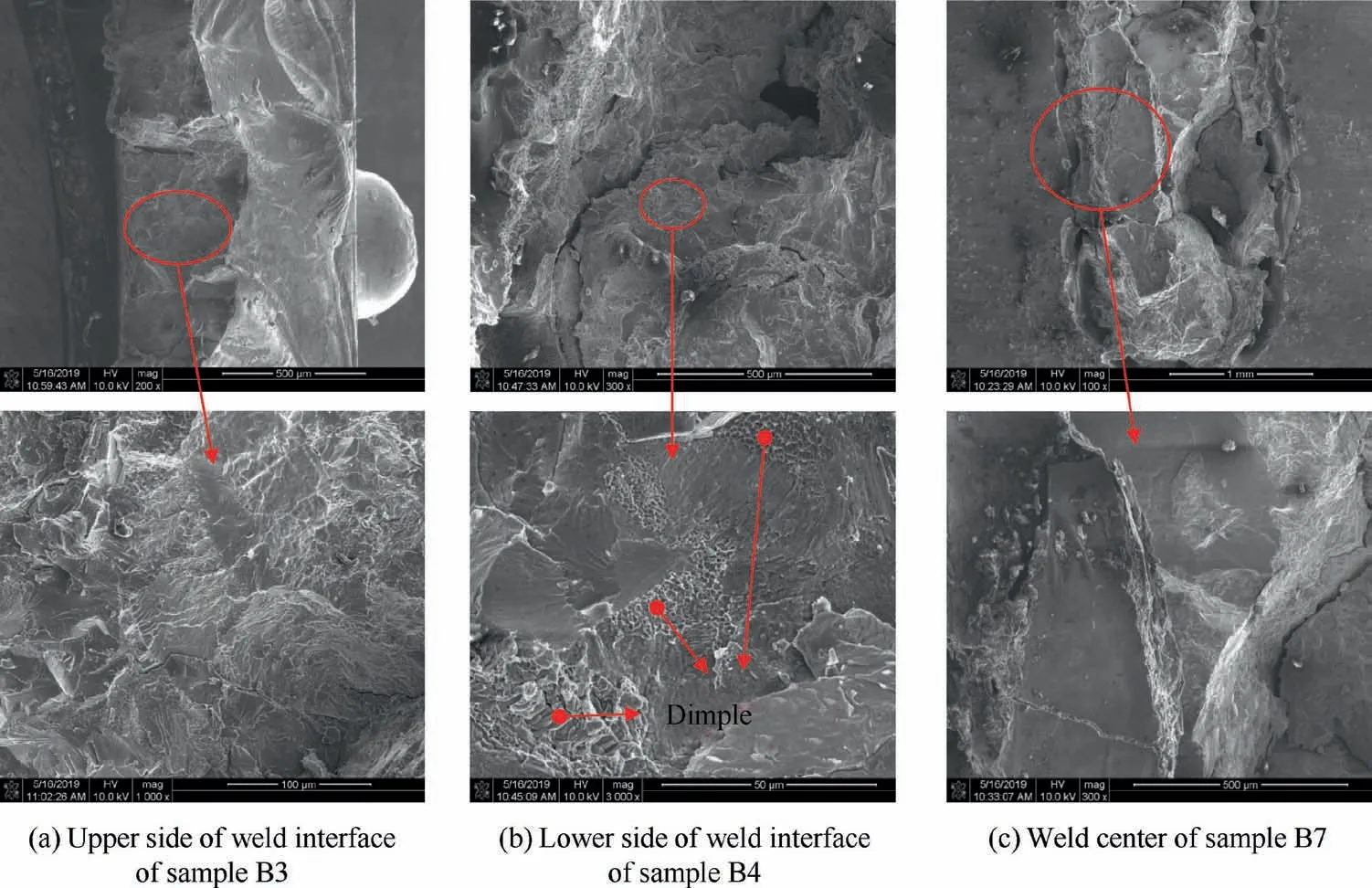
Fig. 14 Shear fracture morphology along different fracture paths.
Most of the published literatures reported that the discontinuous potential phases in the micro-crack tip can lead to the mitigation of the mechanical strength or performance of the welded joint. A better jointing performance under pulsed Nd:YAG laser welding process may be obtained with the formation of continuous intermetallic layer. Tomashchuk et al.reported that in case of centered laser beam position or shift to Ti6Al4V even speed of 5 m/min is enough to create thick interface (90-300 μm) affected by convection. In this case tensile strength drops down to 30%-36%of aluminium weld.Zhu et al.found three different fracture phenomena during the tensile test, which corresponded to different fracture positions at the interface layer, weld seam, and HAZ of the aluminium base metal. The tensile strength of the joint with a thin and uniform IMC layer reached to 80% of the AA6061 tensile strength, and fracture occurred in the HAZ of the aluminium alloy. Wang et al.employed laser-MIG hybrid weldingbrazing without grooves to successfully butt-weld the AA6061 aluminium alloy to the Ti6Al4V titanium alloy. They reported that the average tensile strengths of the reinforced joints can achieve 88% of the AA6061 tensile strength. In this work, by using the optimal laser welding process parameters,the tensile strength of dissimilar pure Ti/Al joint without brazing can be up to about 80%-85%of the aluminium base material. It is very close to the hybrid welding-brazing solution.This means that the quality and the strength of the studied dissimilar Ti/Al joint have a significant improvement after the analysis of HCS.
4. Conclusions
In the present study,the hot-cracking formation of the dissimilar Ti6Al4V/AA6060 lap joint using pulsed Nd:YAG laser welding has been addressed. The influence of the welding process parameters on HCS was experimentally investigated through single-factor analysis. In addition, the shear fracture behavior of dissimilar Ti/Al joint was analyzed through microstructural characterization.The main conclusions drawn from the present study are as follows:
(1) A few deep longitudinal and shallow arc-shaped hot cracks were observed in the weld center of the Ti/Al lap joint. The sources of formation of these hot cracks are associated with the generation of inter-metallic compounds and residual stress in the weld during cooling and solidification. Furthermore, potential additional phases TiAl, TiAl2, and TiAl3 were detected in the region from the weld to the aluminum base material close to the Ti/Al interface.
(2) Pulse overlap exerted less significant effects on the hotcracking susceptibility of the Ti/Al joints compared to the other three pulse parameters. Increasing the pulse peak power and the diameter possibly enable the reduction of hot cracks in the joints,and Ti/Al joints with less number of hot cracks may be obtained by using an appropriate process configuration with peak power percent of 95%, pulse duration of 9 ms, overlap of 50%,and pulse diameter of 1 mm.
(3) Different shear fracture paths in Ti/Al joint are caused by the interaction among the weld surface collapsed amount, the aluminum base metal melt depth, and the welding sample geometry.The shear fracture path along the lower side of the weld interface is different from the other two shear fracture types. Only a small number of dimples are observed along this shear fracture path,and its shear strength is higher than that of the other two fracture modes.
Declaration of Competing Interest
The authors declare that they have no known competing financial interests or personal relationships that could have appeared to influence the work reported in this paper.
Acknowledgement
sThe supports from the National Natural Science Foundation of China (No.51705080, No.51805087), and the Natural Science Foundation of Fujian Province (No.2018J01761,No.2018J01764) are acknowledged.
 CHINESE JOURNAL OF AERONAUTICS2021年4期
- CHINESE JOURNAL OF AERONAUTICS的其它文章
- Time delay compensation in lateral-directional flight control systems at high angles of attack
- Dual stability enhancement mechanisms of axial-slot casing treatment in a high-speed mixed-flow compressor with various tip clearances
- Development cost prediction of general aviation aircraft using combined estimation technique
- Improvement on shaped-hole film cooling effectiveness by integrating upstream sand-dune-shaped ramps
- Modeling and parameter identification of linear time-varying systems based on adaptive chirplet transform under random excitation
- An experimental method to obtain the hard alpha anomaly distribution for titanium alloy aeroengine disks
