Moment-tensor inversion and decomposition for cracks in thin plates
Yu KONG, Min LI, Wimin CHEN, Ning LIU, Boqi KANG
a School of Aeronautic Science and Engineering, Beihang University, Beijing 100083, China
b Institute of Mechanics, Chinese Academy of Sciences, Beijing 100190, China
c School of Engineering Science, University of Chinese Academy of Sciences, Beijing 100049, China
d College of Mechanical and Electrical Engineering, Beijing University of Chemical Technology, Beijing 100029, China
e Key Laboratory of Space Utilization, Technology and Engineering Center for Space Utilization, Chinese Academy of Sciences, Beijing 100094, China
KEYWORDS Acoustic emission;Fatigue;Moment tensor;Source mechanism;Structural health monitoring;Thin plate
Abstract The knowledge of crack type and dislocation orientation is helpful for the lifetime prediction of thin plates on aircrafts.The moment-tensor inversion utilizes the Acoustic Emission(AE)signals to detect cracks and the source mechanisms can be interpreted by the decomposition of moment tensors. Since the traditional moment-tensor inversion is implemented for the AE sources inside infinite elastic bodies,the inversion needs to be modified for the cracks in thin plates.In this study, the moment tensors of cracks in thin plates are derived and the inversion equation is provided based on the Green’s function of second kind. A method of modifying the moment tensors to adapt to the existing decomposition processes and source-type plots is provided. By employing the Finite Element Method(FEM),the wave fields generated by the AE sources are computed.The AE sources continuously changing from pure tensile type (Model I) to shear type (Model II) are achieved in the FE models and the moment tensors are recovered. By the comparison between the reference values and recovered solutions, the source type can be accurately identified in the source-type plot and the applicability of the moment-tensor inversion for cracks in thin plates is confirmed.
1. Introduction
The structure on aircrafts is subjected to fatigue in their service lives and the application of cyclic load causes fatigue cracks to initiate and advance. The structure healthy monitoring is extremely important for predicting the remaining fatigue life of aircraft structure.Aircraft metallic structures can be inspected by many methods,such as visual inspection, radiography,eddy current testing,optical and ultrasonic method.However,these methods require the aircraft to be taken out of service and can be quite time consuming.Consequently, a method of real-time nondestructive monitoring is needed.
The Acoustic Emission (AE) monitoring is a convenient method for a quick and continuous inspection of the structures with possible cracks. It can nondestructively detect crack growth in metalsand has been applied in many structures,such as wind turbine blade,steel bridgeand aircraft.The parameters used to assess the remaining fatigue life of structures can be obtained by the AE analysis and include crack length,crack growth rate and stress intensity.The principle of AE monitoring is to establish the relationships between the crack parameters and AE parameters,which can be cumulative events, hits, duration, average frequency and rise time.Because each material has its own crack growth behavior, the establishment of these relationships requires the studies of different representative constructions and can be quite miscellaneous and toilsome. In addition, the traditional AE monitoring can hardly provide the exact information of dislocation orientations and crack types, which are quite useful for life monitoring. Specifically, during fatigue crack growth, the transition between the tensile and shear modes can be evident, especially in thin sheet material.However,the crack growth behavior to the tensile mode is different from that to the shear modeand specific propagation criteria are needed for each mode. Consequently,identifying crack types is valuable for the prediction on fatigue crack growth and estimation of fatigue life. In addition, crack types are related to some factors, such as loading typesand environment.The knowledge of crack types can help to assess the working conditions of structures.
For identifying the dislocation orientations and types of cracks, the moment-tensor inversion can be introduced. The moment-tensor inversion uses the radiation pattern of AE waves to identify the crack typeand the corresponding inversion equation is only dependent on the parameters of materials.Compared with the traditional AE monitoring method,the moment-tensor inversion can provide explicit geometric descriptions of cracks and the interpretation of source mechanisms.The moment-tensor inversion is originally used to interpret the source mechanisms of earthquakesand has also been applied to the AE monitoring in rocks.A moment tensor contains 9 components, in which 6 components are independent and each one represents a moment.The moment tensor can be computed by the amplitudes of AE waves obtained by sensors. For physically interpreting source mechanisms, the decompositions and source-type plots of moment tensors were studied.In the traditional applications of the moment-tensor inversion, body wavesare more commonly used, because its expression is quite simple.It is proved that the reliability of the moment-tensor inversion is independent of the absolute size of the model.which means the moment-tensor inversion can be applied to small structures.
The traditional moment-tensor formulas are only suitable for the cracks inside elastic bodies, such as microearthquakesand AE events in rocks.However, on the aircraft,thin plates are quite commonand the cracks in thin plates can be a form of penetration.Ohtsu et al.investigated the moment-tensor inversion in two-dimension models,but the cracks in this study were still regarded as point sources inside the body and different from the penetrating cracks.Furthermore, the waveform in thin plates is different from body waves, which means the inversion equation needs some modifications. In this study, we derive the moment tensors of the cracks in thin plates and modify the inversion equation. In addition, a method is proposed to adapt the moment tensors of the cracks in thin plates to the existing decompositions and source-type plot. The numerical models of crack opening are established and the AE wave fields are computed. The moment-tensor inversion is applied to the numerical tests for validating its performance and effectiveness.
2. Formulas
2.1. Moment tensor of cracks in thin plates
According to Aki and Richards,AE waves due to the displacement discontinuity on crack surface are represented by the integral representation as:

where u(x, t) is the nth component of the waveform at position x, t is the time, [u] represents the relative displacement between the two crack surfaces.vis the component of the normal vector to the crack surface (as shown in Fig. 1). [u] is the relative dislocation vector of the crack surfaces.v is the normal vector to the crack surface.
care the elastic parameters of the medium and represent the linear relationship of Eq.(2).τis the component of stress tensor and eis the component of strain tensor. Gis the Green’s function of second kind and ∑is the crack surface.
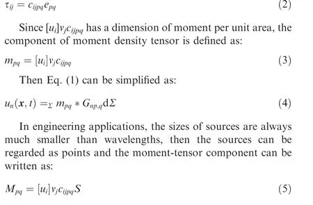
where S is the crack size.Moment-tensor components have the dimension of moment.
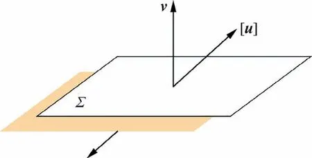
Fig. 1 Model of a crack.
Based on Eq. (5), a crack is transformed to a group of equivalent forces acting at the position of the crack. The dynamic response of the group of forces is the same as that of the crack opening. Every two forces in the group form a couple or a vector dipole with forces and arm in the same direction. Nine couples and vector dipoles can be obtained and the corresponding values are orderly arranged as a moment tensor. Then, the inversion for crack parameters is transformed to the inversion for moment tensors, because the elastic waves induced by crack opening can be easily expressed in terms of moment tensors according to the Green’s function of second kind.In other words,moment tensors and the elastic waves induced by crack opening are mainly determined by the global dislocations of crack surfaces. Moment tensors can be regarded as the mathematical expressions of cracks and indicators of the stress fields around cracks.Moreover, explicit dislocation orientations and crack types can be obtained by further decomposition of moment tensorsand help to evaluate the fatigue life.
In thin plates,the crack with a form of penetration is quite common (as shown in Fig. 2).
Considering the plate is very thin, it is logical to assume that the crack surface is vertical to the plate and the displacement of the element on the crack surface is unchanged with thickness. In other words, the normal vector to the crack surface and the dislocation vector of the crack surface are located in the plane. Then the thin plate can be regarded as a planestress model and the elastic constants are expressed as:

where λ and μ are the Lame’s constants. The momenttensor components M, M, Mand M, which represent the in-plane couples and vector dipoles, can be calculated by Eqs.- and the other 5 components are zero according to the plane-stress hypothesis. The moment tensor of cracks in thin plates can be written as:

It should be noted that the moment tensor M is symmetrical and M=M. Consequently, three of the four non-zero components are independent and need to be solved.
2.2. Moment-tensor inversion for cracks in thin plates
Actually,it is difficult to solve for the displacement set up by a unidirectional point body force acting with time-varying magnitude at a fixed point in thin plates.Consequently,referring to the Green’s function of second kind in unbounded media, we are concerned about the in-plane part of the threedimensional radiation pattern and hope that it can character the spatial dependence of the amplitudes of AE first motions.According to the analysis in Section 2.1, only three independent components need to be solved and the other six can be computed by the three components. Consequently, at least three sensors are needed for the inversion of one AE source.Each sensor can provide an equation containing three unknown moment-tensor components as follows:

where,A(x)is the amplitude of the first motion of AE signal at x. Cis the physical coefficient containing sensor sensitivity. R is source-sensor distance. ris the direction cosine from the source to the sensor.Then a linear algorithm containing at least three equations is obtained and can be written as:

where A is a vector containing the amplitudes of first motions. G is a matrix determined by the Green’s function and the positions of sensors. m denotes the moment tensors in vector format. This equation can be solved by the leastsquares method:

In thin plates, the waveform changes from spherical wave to cylindrical wave,then the waves attenuate as R,in which R is the propagation distance. In addition, the dispersion of waves is ignored in the inversion,because only the first motion of AE waves is used in the inversion.This simplification has no influence on the moment-tensor inversion, which can be validated in the numerical tests.
2.3. Decomposition of moment tensor

Fig. 2 Crack in thin plate.
After the moment tensor of a crack is obtained,the orientation of dislocation and type of source can be calculated by the decomposition of the moment tensor. The principle of the decomposition is to restructure the moment tensor to a combination of the three basic sources: the Isotropic (ISO),Double-Couple(DC)and Compensated Linear Vector Dipole(CLVD)sources.The source type can be clarified by the proportions of the three sources in moment tensors and the dislocation orientation can be calculated by the eigenvectors of moment tensors. However, in thin plates, the basic sources of ISO and CLVD do not exist, because the out-of-plane motion of the crack surface is zero. In addition, the physical mechanisms of the eigenvalues and eigenvectors of the moment tensor are different between the cracks in thin plates and those in unbounded media. For the cracks in unbounded media, the methods of moment-tensor decomposition and source-type interpretation are very complete and mature. It will be quite beneficial to modify the moment tensors of cracks in thin plates to adapt to the existing methods.
Here, the method of modification is provided and the moment tensor of Eq. (7) can be transformed to the corresponding form that can be processed. Based on the difference of the tensile axis, the moment-tensor components should be multiplied by different coefficients, which can be obtained by the comparison of the elastic constants between unbounded media and thin plates. The modification is written as:
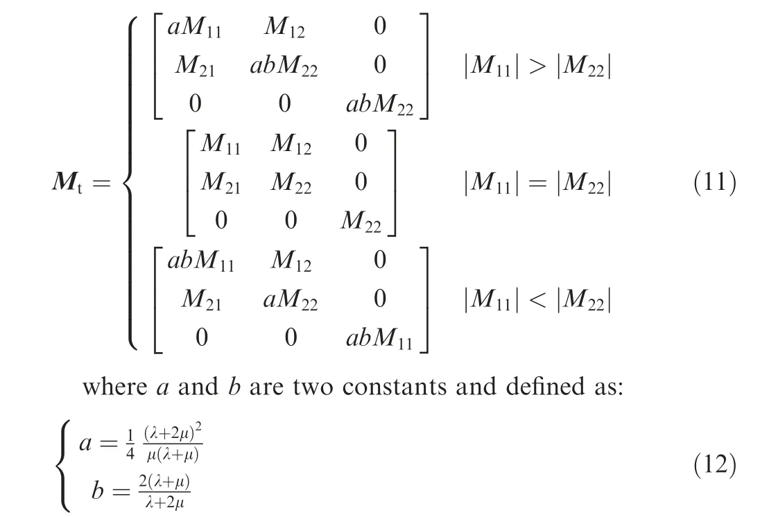
By the modification of Eq. (11), the moment tensors of cracks in thin plates are transformed to the corresponding forms that can be processed. Then the dislocation orientation and source type can be calculated by the existing formulas,which have been studied in detail.
For computing the dislocation orientation of the crack surface,themomenttensorMcanbedecomposedusingeigenvalues and an orthonormal basis of eigenvectors in the following way:

where M≥M≥M,and vector e,eand edefine the T(tensile), N (intermediate or neutral) and P (pressure) axes,respectively. The dislocation and normal vectors of the crack surface can be computed by Eq. (14).

where uis the dislocation orientation and defined as u=[u]/|[u]|. For interpreting the source type, the moment tensor Mcan be diagonalized and restructured into a combination of three basic sources: ISO, DC and CLVD as follows:
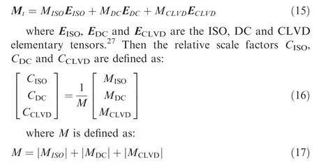
Based on the relative scale factors, the positions of sources can be located in Fig.3,which is called the diamond CLVDISO plot and put forward by Vavrycˇuk,and the source type can be determined visually.
3. Numerical tests
3.1. Models
In order to illustrate the effectiveness of the moment-tensor inversion for cracks in thin plates,we study a group of cracks,which the normal vector v is unchanged and the dislocation vector [u] is continuously changing (as shown in Fig. 4). The wave fields induced by those cracks are needed for verifying the inversion approach proposed in this study. In laboratory environment,crack types are dependent on various factorsand different crack types with specific dislocation orientations are complicated to generate. Thus the Finite Element Method(FEM)is used in this study to compute the wave fields induced by crack opening.
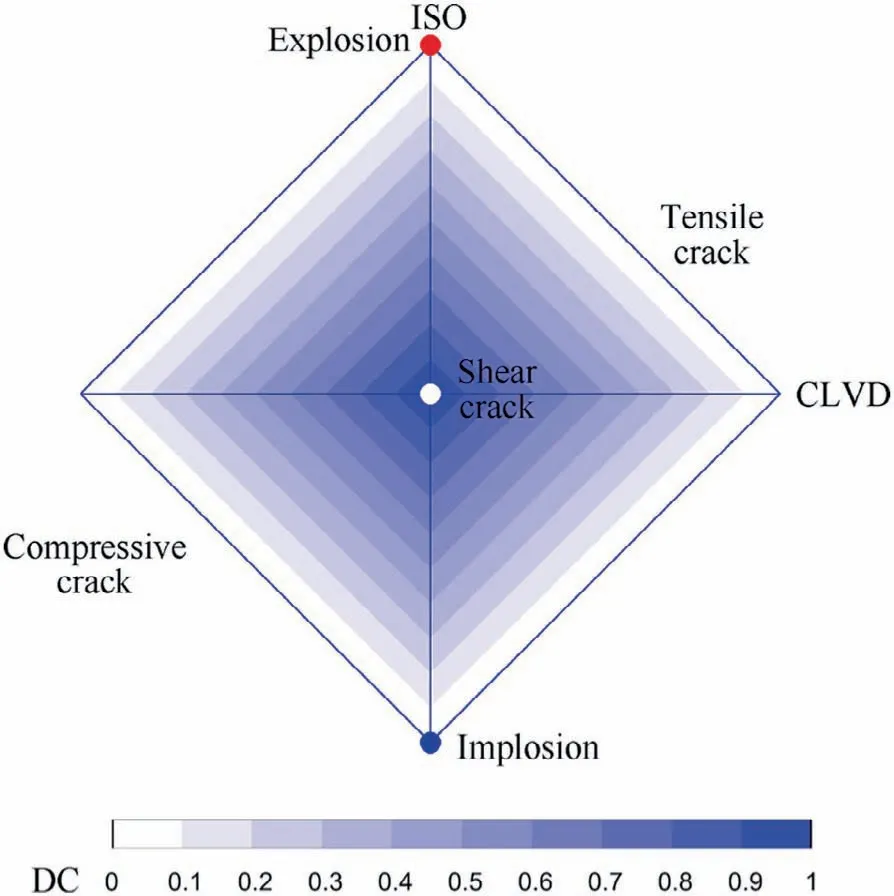
Fig. 3 Source-type plot determined by relative scale factors of ISO, DC and CLVD [27].
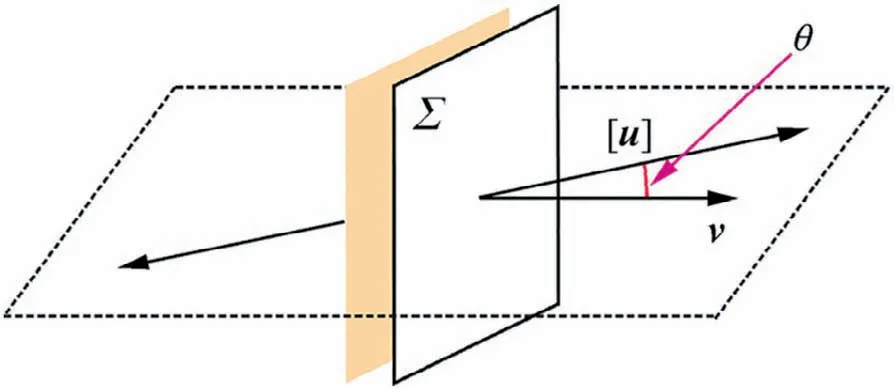
Fig. 4 Cracks with unchanged normal vector v and various dislocation vector [u].
In Fig.4,θ is the angle between the normal vector v and dislocation vector [u]. The normal vector v is unchanged and the angle θ changes from 0° to 90°, then the crack type changes from pure tensile (Mode I) to shear (Mode II). Although the dislocation type near a crack tip can be affected by many factors, such as grain shapes, sizes and deformation levels, the elastic waves induced by crack opening are mainly dependent on the global dislocations of crack surfaces.Consequently,in FE models,the opening of cracks can be achieved simply by the time-dependent forces acting on the crack surfaces (as shown in Fig. 5 (a)). As long as the dislocations of crack surfaces in FE models are the same as those of real cracks, the elastic waves computed by FEM are reliable and the complexity of crack tips can be ignored in FE models. In addition,more proper parameters will be set for FEM to ensure the correctness of the simulation.
The thickness of the plate is 0.01 m and the length of the plate is 2 m. 4 sensors locate on the top surface of the plate and the distance Ris 0.7 m (as shown in Fig. 5 (b)), which can avoid the effect of the wave reflection by the boundary.
In the synthetic tests, the thin plate is a 3-D FE model,rather than a plane-stress model.The material of the thin plate is aluminum and the material parameters are listed in Table 1.
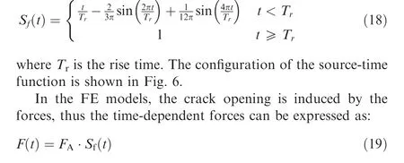

Table 1 Material parameters in FE models.
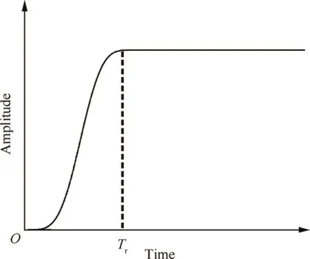
Fig. 6 Configuration of source-time function.
The opening state of crack surfaces can be described by the source-time function. A representative source-time function is expressed according to Ohtsuas:where Fis the amplitude of the force and determines the degree of crack opening. According to Cai et al.,the dominant frequency of AE waves is about 10Hz, then the value of Tis 10s.
Because the moment-tensor inversion is dependent on the relative amplitudes of elastic waves in different directions,the accuracy of inversion solutions is very sensitive to the directional dependence of errors. Consequently, the plate is meshed by pentahedral elements, which can almost remove the directional dependence of numerical error.
For the FEM of simulating wave propagation,the accuracy of numerical solutions is dependent on the time and spatial discretization.For the stability of FEM, the time step is required to be less than the time of wave passing through an element.In the FE models, the time step is 1.5×10s and the shortest time of waves passing through an element is about 3.5×10s. In addition, for suppressing the effect of numerical dispersion caused by spatial discretization, 15 elements are contained within one wavelength, then the maximum dispersion error is less than 0.5%.These measures can ensure the correctness of the wave-propagation simulation.
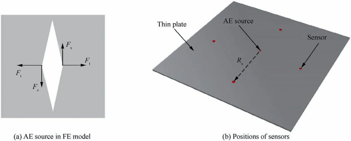
Fig. 5 AE source in FE models and relative positions between AE source and sensors.
Based on the same way of achieving crack opening, timeand spatial-discretization criteria as above,the FEM was used to compute the wave fields induced by the cracks inside unbounded media.In unbounded media, the Green’s function of second kind can accurately describe the wave fields induced by crack opening. The wave fields computed by the FEM are in good agreements with the theoretical solutions,which are computed by the Green’s function of second kind.The maximum inversion errors of the moment tensors recovered by the FE solutions are less than 3%, which can ensure the reliability of FEM.Although the shape of thin plates is different from that of unbounded media, the way of achieving crack opening, time- and spatial-discretization criteria are the same. It is logical that FEM is still reliable in this study. Consequently, in this study, the FE solutions are regarded as the reference values to verify the accuracy of the simplified Green’s function for thin plates.
3.2. Results
Because the moment-tensor inversion bases on the difference of wave amplitudes in different directions to identify crack types, it is more distinct to compare the wave amplitudes between the derived results and reference values, and the graphs showing the change of wave amplitudes in space are called radiation patterns. According to Eq. (1), any crack can be decomposed into a tensile(Mode I)and a shear(Mode II) cracks, which are two basic types and independent of each other.Consequently, the comparative patterns of Mode I and II cracks are sufficient to verify the derived results for any general condition with combined Mode I and II cracks.The radiation patterns of pure tensile (Mode I) and shear(Mode II) cracks with unit amplitudes are plotted in Fig. 7.
As stated in Section 2.2,the Green’s function in thin plates is simplified from the Green’s function in unbounded media.In Fig. 7, the radiation patterns of the reference values (represented by the asterisks) is the same as these of the derived results (represented by the solid lines), which indicates that the simplified Green’s function is applicable to the momenttensor inversion for cracks in thin plates and the moment tensor can be recovered by Eq.(8).In order to illustrate the source type visually, the source-type plot based on the modification and decomposition of moment tensors is shown in Fig. 8.The moment tensors are recovered based on the synthetic waveforms.
As shown in Fig. 8, the decomposition of the moment tensors modified by Eq. (11) can accurately indicate the source types,which are visually illustrated by the corresponding positions of the triangles. Originally, the moment-tensor inversion for cracks in thin plates ignores the out-of-plane motion of crack surface and the moment tensor can not be decomposed into ISO,DC and CLVD sources directly.By the modification of Eq. (11), the moment tensor directly recovered by the AE signals is transformed to the corresponding form that can be decomposed by the existing methods. The decomposition results can correctly indicate the type of the source, which proves that the modification is correct and effective. It should be noted that the modification is just a mathematic way to adapt the moment tensors of cracks in thin plates to the decomposition method for cracks in unbounded media.
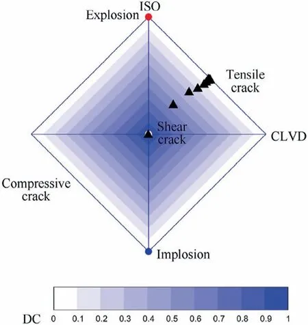
Fig. 8 Source-type plot of cracks changing from pure tensile(Mode I) type to shear (Mode II) type. Each triangle represents a source and the source type can be determined by the position of the triangle.
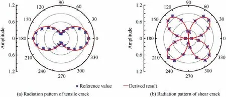
Fig.7 Comparison of radiation patterns between the reference values and derived results.Two source types of pure tensile(Mode I)and shear (Mode II) cracks are involved.
4. Conclusions
Compared with other AE monitoring methods, the momenttensor inversion can provide more detailed descriptions of cracks,such as explicit dislocation orientation and source type.However, the traditional moment-tensor inversion is not suitable for the cracks in thin plates. In this study, we derive the moment-tensor form for the cracks in thin plates and provide the inversion equation based on the Green’s function in unbounded media. In order to adapt the moment tensors of cracks in thin plates to the existing decomposition method and source-type plot, a method of modification for the moment tensors is proposed. According to the modified moment tensors, the dislocation orientation of the crack surface can be computed by the eigenvectors and the source type can be visually identified in the source-type plot.The inversion method is also applied to the synthetic AE tests.The momenttensor solutions can visually and accurately interpret the source types, which indicates the superiority of the momenttensor inversion for cracks in thin plates.
Declaration of Competing Interest
The authors declare that they have no known competing financial interests or personal relationships that could have appeared to influence the work reported in this paper.
Acknowledgement
sThe authors of this paper would like to thank the financial supports provided by the Strategic Priority Research Program of the Chinese Academy of Sciences (No. XDA22000000) and National Natural Science Foundation of China (No.41804134).
 CHINESE JOURNAL OF AERONAUTICS2021年4期
- CHINESE JOURNAL OF AERONAUTICS的其它文章
- Time delay compensation in lateral-directional flight control systems at high angles of attack
- Dual stability enhancement mechanisms of axial-slot casing treatment in a high-speed mixed-flow compressor with various tip clearances
- Development cost prediction of general aviation aircraft using combined estimation technique
- Improvement on shaped-hole film cooling effectiveness by integrating upstream sand-dune-shaped ramps
- Modeling and parameter identification of linear time-varying systems based on adaptive chirplet transform under random excitation
- An experimental method to obtain the hard alpha anomaly distribution for titanium alloy aeroengine disks
