Effective metal mold method for the production of bionic adhesives based on electrochemical modifications
Cong YUAN, Keju JI, Yiqing TANG, Zizhuo WANG, Enhu CUI,Jin CHEN, Zhendong DAI
a Jiangsu Provincial Key Laboratory of Bionic Functional Materials, College of Mechanical and Electrical Engineering,Nanjing University of Aeronautics and Astronautics, Nanjing 210016, China
b College of Mechanical and Electrical Engineering, Hunan City University, Yiyang 413000,China
KEYWORDS Bionic adhesive;Dry adhesion;Electro-deposition;Metal mold;Micro/nano-imprint;Micro-porous
Abstract Bionic adhesives with tip-expanded microstructural arrays have attracted considerable interest owing to their high adhesive performance at low preloads.Their mainstream manufacturing method is molding.Due to most molds are made of silicon or silicon-based soft templates,and have poor wear resistant or vulnerability to high temperature, limiting their use in large-scale manufacturing. Nickel is widely used as an embossing mold in the micro/nano-imprint industrial process owing to its good mechanical properties.However,the processing of metal molds for the fabrication of tip-expanded microstructural arrays is extremely challenging. In this study, using electrodeposition techniques, the shape of the micropores is modified to obtain end-controlled pores. The effect of the non-uniformity of the electric field on the microporous morphology in the electrodeposition process is systematically investigated. Furthermore, the mechanism of non-uniformity evolution of the microporous morphology is revealed.The optimized microporous metal array is used as a mold to investigate the cavity evolution laws of the elastic cushions under pre-load during the manufacturing process.As a result,typical bionic adhesives with tip-expansion are obtained.Moreover,corresponding adhesion mechanics are analyzed. The results show that electrochemical modifications have broad application prospects in the fabrication of tip-expanded microstructures, providing a new method for the large-scale fabrication of bionic adhesives based on metal molds.
1. Introduction
Many organisms in nature exhibit excellent adhesion to vertical surfaces and even ceilings,such as geckos,beetles,and spiders. This so-called ‘‘dry adhesion” is possible owing to the special microscopic structure at the base of their feet.Inspired by this biological function, scholars have developed bionic adhesives with a variety of geometrically characterized microstructuresfor applications in biomedicine,robot handling,climbing robots, and space operations.Among them, bionic adhesives with tip-expanded microstructural arrays have attracted considerable attention owing to their high adhesion performance at low preloads.As a result, many innovative methods for fabricating such tipexpanded microstructural arrays have emerged.
Molding is the mainstream method for manufacturing tipexpanded microstructural arrays of bionic adhesives. This method typically involves pouring polymer into a mold for curing and releasing and directly or indirectly produces mushroom-shaped microfiber bionic adhesion materials.Currently the mold used for directly molding tip-expanded microstructural arrays of bionic adhesives are generally manufactured by etching or lithography technology,so the choice of material is limited.Generally,photosensitive materials, such as silicon-based materials or photoresists, are used,which are not only expensive to process and dimensionally limited but also prone to wear or damage. Recently, increasing research has focused on the large-scale manufacturing of bionic adhesives to advance the practical engineering applications.Lee et al.manufactured a silicon mold using lithography and deep silicon etching techniques and copied and fixed a polyurethane acrylate template on a polyethylene terephthalate film to make a ribbon mold.They achieved the continuous production of bionic adhesives with tip-expanded microstructure array.Yu et al.used ePDMS(two-component polydimethylsiloxane Elastosil® M4601) as the soft templates and bonded them to smooth rollers to make embossed rollers, achieving the continuous manufacturing of bionic adhesives with tipexpanded microstructure arrays. The manufacturing of the above-mentioned molds is complex and their service life is short owing to the development of wear or damage.Therefore,the development of abrasion and high temperature resistant and expandable molds is essential for the large-scale application of tip-expanded microstructural arrays.
In the micro/nano-imprint industrial process, the high strength and wear resistance of metal-based molds is a common solution for scale up processes and shows broad application prospects in the fabrication of microstructures, such as microprisms and gratings. However, this type of microstructures is not tip-expandable. Although metal-based mold manufacturing has been relatively well implemented, the tipexpansion of microstructure to metal molds and the regulation of the microstructure mold cavity are challenging.
In this study, a microporous metal array modification technique based on electrodeposition is developed. This technique achieves the controlled modification of the throughhole shape of large-scale arrays. Furthermore, we investigate the influence of electric and flow fields on the through-hole cavity shape to achieve the fabrication of bionic adhesion materials for tip-expanded microstructural arrays. The technique is shown to have high efficiency and allow the appearance control and regulation in the manufacturing of bionic adhesives, providing a new method for the large-scale manufacturing of bionic adhesives.
2. Experiment
2.1. Manufacturing of metal template
The metal template is a key component of the molding process to produce bionic adhesives. SUS304 stainless steel with a thickness of 0.06 mm was used as the substrate; it was laser processed to obtain a cylindrical through-hole array (Fig. 1(a)). Because laser drilling leaves some slag around the hole and the stainless steel surface easily generates a dense passivation film a pre-treatment was carried out before nickel plating to obtain a good plating layer and avoid undesirable phenomena such as layering,peeling,and shedding.After laser drilling,the stainless steel strip was dipped into a 10wt% oxalic acid solution and ultrasonically cleaned in an alkaline degreasing agent for 20 min and then with deionized water until the slag was removed. Then, the samples were impregnated with 37%HCl at 25°C for 0.5-1 min to activate the surface. Finally,the nickel sample was pre-plated. The pre-treated throughhole stainless steel sheet was then moved into the plating bath as the electrodeposition cathode and a nickel sheet was used as the anode; the two electrodes were installed parallel to each other. Through-hole with flaring at both ends was obtained after the electrochemical modification(Fig.1(b)).The solution formula and process specifications for nickel pre-plating and plating are shown in Tables 1 and 2,respectively.All solutions were based on analytical pure chemicals and cleaned with newly produced deionized water; the PH of the plating solution was adjusted with dilute sulfuric acid and sodium hydroxide.
2.2. Manufacturing of bionic adhesives with tip-expanded microstructural arrays
Fig. 1(c) shows a schematic of the manufacturing process of the bionic adhesives with tip-expanded microstructural arrays by metal mold. The array of microporous metal templates manufactured by electrochemical techniques fit closely to the elastic cushion under a certain pressure;the elastic cushion will induce small deformations, so the tip shape of the microstructure can be regulated by adjusting the pressure. The prepolymer used to cast the bionic adhesives was PDMS (SYLGARD184 Silicone Encapsulant Kit, Dow Corning, America),(Sylgard 184A).A curing agent(Sylgard 184B)was mixed uniformly at a mass ratio of 10:1,vacuum degassed,cured and demolded; Fig. 1(d) shows a schematic of final bionic adhesives.
To study the effect of the electrodeposition time on the pore shape of the metal templates and the adhesion properties of the bionic adhesives, the pressure between metal templates and elastic cushions was set to 0.3 MPa. The metal templates were electrodeposited for 0, 1, 1.5, and 2 h, and cured at 70°C for 2 h.
To study the effect of the pressure on the bionic adhesives,metal templates with electrodeposition modifications of 1 h were selected and the pressure was adjusted to 0.1, 0.3, 0.5,and 0.7 MPa, and cured at 70°C for 2 h.
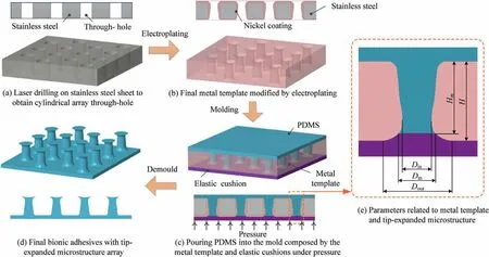
Fig. 1 Schematic of manufacturing process of bionic adhesives with tip-expanded microstructural arrays by metal mold.
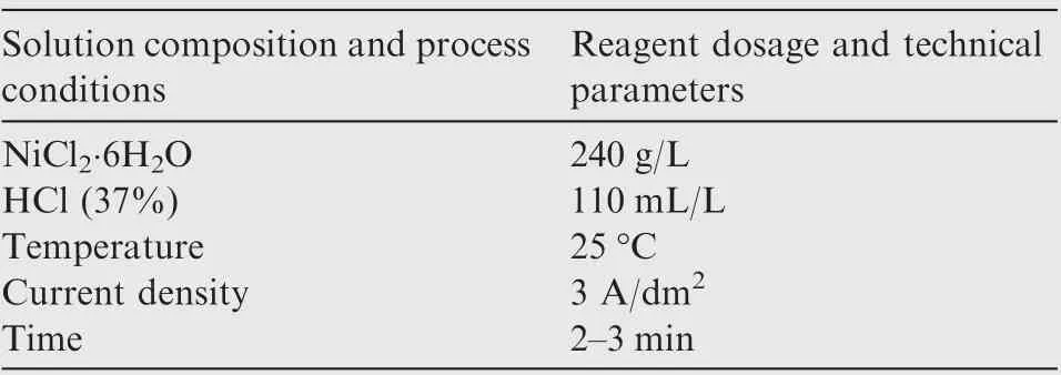
Table 1 Formulations and process specifications for preplating solution.
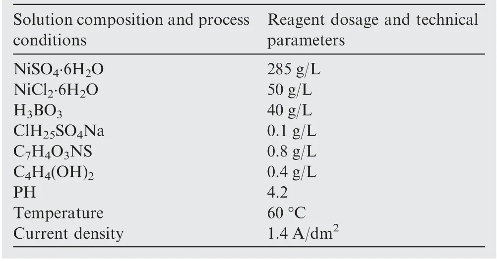
Table 2 Formulations and process specifications for plating solution.
2.3. Characterization
2.3.1. Mold cavity and tip shape
For ease of description, the mold cavity and tip shape of the bionic adhesives are characterized as follows (Fig. 1(e)): the height of the microstructure His defined as the distance from the tip of the microstructure to the root;the tip diameter of the microstructure Dis defined as the diameter of the expanded tip; the ‘‘neck” diameter of the microstructure Dis defined as the minimum diameter of the rod; the depth of the metal through-hole H is defined as the thickness of the metal template; the opening diameter of through-hole Dis defined as the maximum diameter of the through-hole after being modified by electrochemical techniques.
2.3.2. Adhesion test
Adhesion was tested on a custom force measuring device. The adhesion of all samples was tested at 25 ℃and at a relative humidity of (50±10) %. To facilitate the characterization of adhesion strength, the fabricated bionic adhesives were cut into small 10 mm×10 mm pieces and flatly adhered to the press head with the binder. They were moved downward at 5 mm/min against the glass adhesion surface to a predetermined preload. The preload was maintained for 5 s to ensure adequate contact at the adhesion interface. Subsequently, the sample was retracted at a constant velocity until complete detachment,thereby providing a measure of the adhesion performance. The adhesive strength was determined by dividing the maximum pull-off force by the sample area. To study the effect of preload on adhesive strength,bionic adhesives manufactured under a pressure of 0.3 MPa were selected as the test sample,and experiments were carried out at five preload values(0.01,0.02,0.03,0.04,and 0.06 MPa)with a retraction velocity of 10 mm/min. To study the effect of retraction velocity on adhesive strength, experiments were carried out at seven retraction velocities (1, 2, 5, 10, 15, 20, and 30 mm/min) with a preload of 0.02 MPa.To study the adhesive strength between metal templates and elastic cushions of bionic adhesives manufactured under different pressures (0.1, 0.3, 0.5, and 0.7 MPa), experiments were carried out with a preload of 0.02 MPa and a retraction velocity of 10 mm/min.
3. Results and discussion
3.1. Metal template product
Fig. 2(a)-(c) shows top-view SEM images of the metal template produced with electrodeposition time of 1, 1.5, and 2 h,respectively. It can be seen that samples have uniform through-hole shape and possess good surface quality. Fig. 2(d) shows the cross-section and geometric dimensions of the through-holes after electrodeposition. It can be seen that the through-holes obtained by laser processing without plating modification(plating time of 0 s)are cylindrical,and their side walls are almost vertical, so Dand Dare equal (approximately 80 μm). After 1 h of plating modification, the right angles at both ends of the through-hole become smooth and rounded; Dshrinks to approximately 60 μm, and Dincreases slightly to approximately 90 μm. After 1.5 h of plating, Dreduces to approximately 40 μm, and Dremains almost unchanged. After 2 h of plating, Dfurther reduced to approximately 20 μm (some through-holes become completely closed), and while Dchanges slightly. These results reveal that only Dshows a clear tendency to shrink as the plating time increases, while Dremains almost constant,even when Dshrinks almost to zero.
Electroplating is a very complex process, which includes electric fields, chemical reactions, material and heat transfer,and other physicochemical processes, and these physicochemical factors interact to affect the deposition of nickel on the cathode surface. Furthermore, the through-hole of the plating modification in this experiment, which is on the micron scale,is difficult to describe with the available experimental means.To overcome this limitation, in this study, we employed the commercial software COMSOL Multiphysics to simulate the evolution of the metal through-holes.
The microporous electrochemical modification process can be briefly described as follows (Fig. 3(a)): stainless steel sheets with cylindrical through-hole arrays and nickel plates are immersed in the electroplating solution as cathode and anode,respectively. With the assistance of a direct current, the nickel on the surface of the nickel anode loses electrons in the form of nickel ions into the electroplating solution;these electrons diffuse and migrate to the cathode surface and are deposited as metallic nickel on the microporous surface to form a plating layer. Stainless steel sheets were installed parallel to the anode during electroplating to enhance the non-uniformity of the local current density distribution on the cathode surface and improve the non-uniformity of the deposition rate of metallic nickel in different regions, thus facilitating the modification of the through-hole shape. Fig. 3(b) shows the concentration of nickel ions in the electrolyte around the hole at the 5th second of plating, showing that the nickel ions not being replenished in time. Fig. 3c shows the initial current density distribution on the surface of the cathode. It can be seen that,at the beginning of plating, the local current density is highest at the opening of the through hole near the anode.
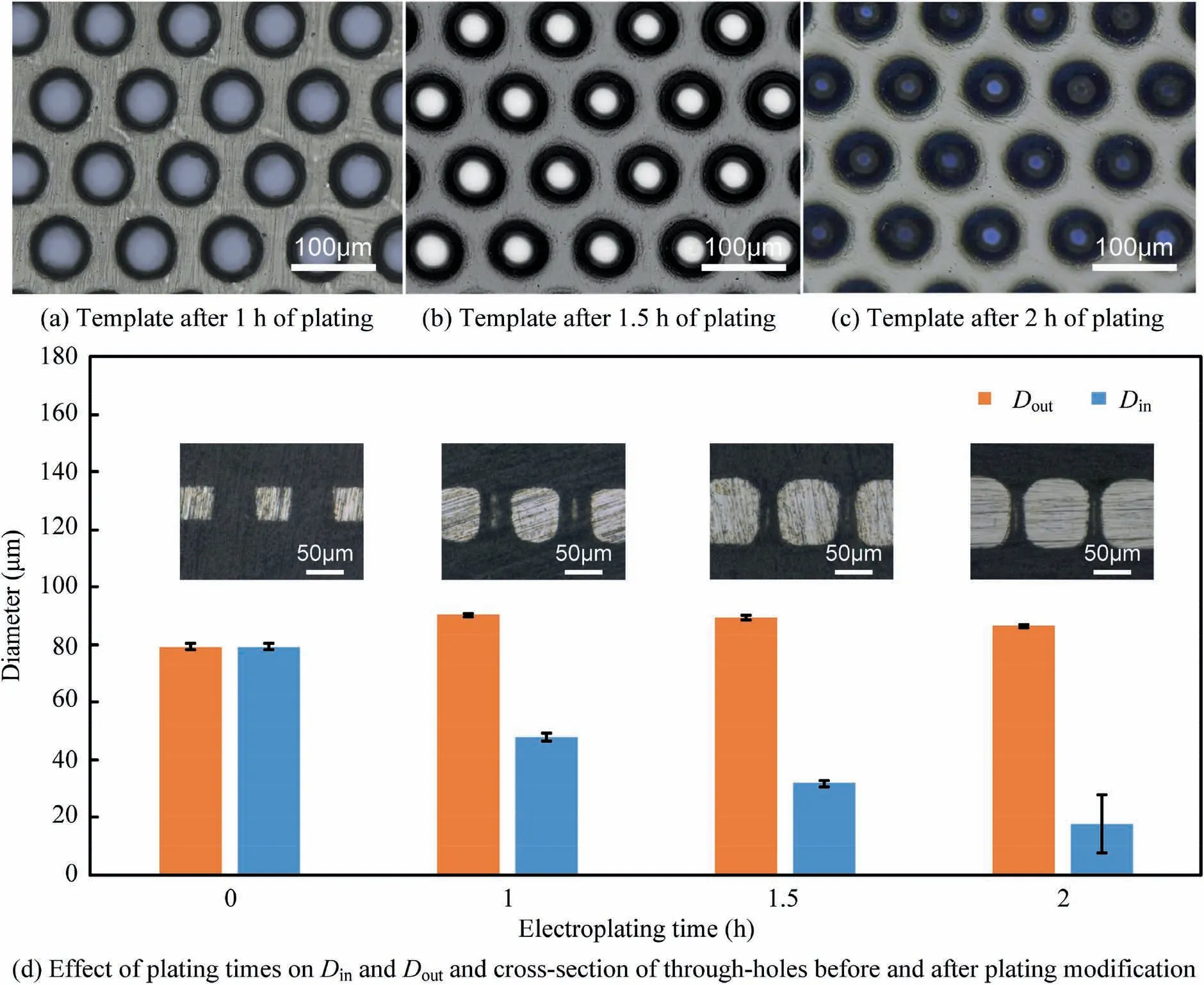
Fig. 2 Effect of different plating time on shape of through-holes.
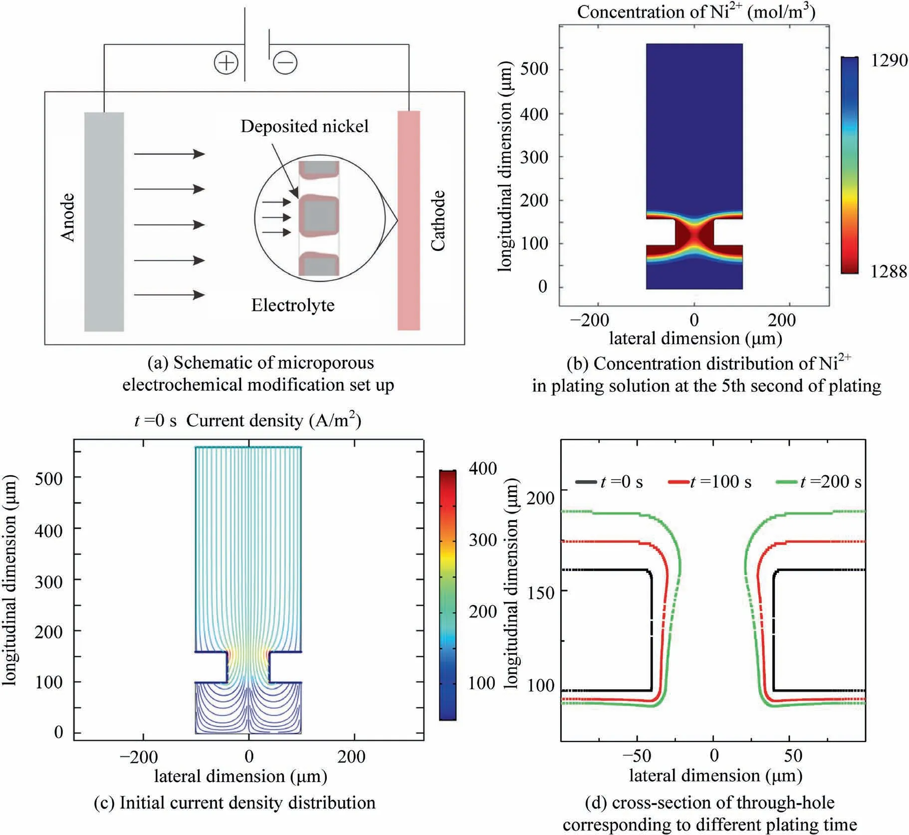
Fig. 3 Simulation results of through-hole evolution.
According to Faraday’s law, the deposition rate of nickel on the cathode surface v (m/s) can be calculated as follows:

In the above equation, M is the average molar mass of a nickel atom (59 g/mol), ρis the density of nickel (8900 kg/m), n is the number of electrons participating in the reaction,F is the Faraday constant, and iis the local current of the cathode, which can be calculated as follows:

where iis the exchange current density, αand αare the transfer coefficients on the anode and cathode, respectively,R is the molar gas constant, T is the plating temperature,and ƞ is the over-potential of the cathode, Cand Care the concentration of reduced and oxidized substances on the electrode surface. Thus, the rate of deposition at a particular location on the cathode surface is mainly influenced by the local current density and concentration of nickel ions. Based on the above analysis,the previous experimental phenomenon can be explained as follows.At the beginning of plating,owing to the‘‘tip”effect caused by the current density at the throughhole opening and the different concentration of nickel ions around the through-hole, the fastest growth of the plating layer occurs at the opening near the anode, where the ‘‘neck”is formed, while the original right angle of the opening has a rounding effect. The cross-section of the through -hole corresponding to different plating times obtained by the simulation is illustrated in Fig.3(d).The relationship between plating time and feature size satisfies Eq. (1) in theory, provided that the current density and other parameters are constant. In terms of feature size (Dand D), the simulation results only indicate topographic trends for 200 s, while actual measurements show trend results for 2 h. This is because the holes in the actual molds were considerably smaller; therefore, the plating time required was relatively long. It is worth noting that there is still a small discrepancy between the simulation results and the experimental results shown in Fig. 2,because in the actual plating process,the effect of the size of the microporous structure on the distribution of the plating liquid flow field is not well represented; this will be considered in our future theoretical simulations.
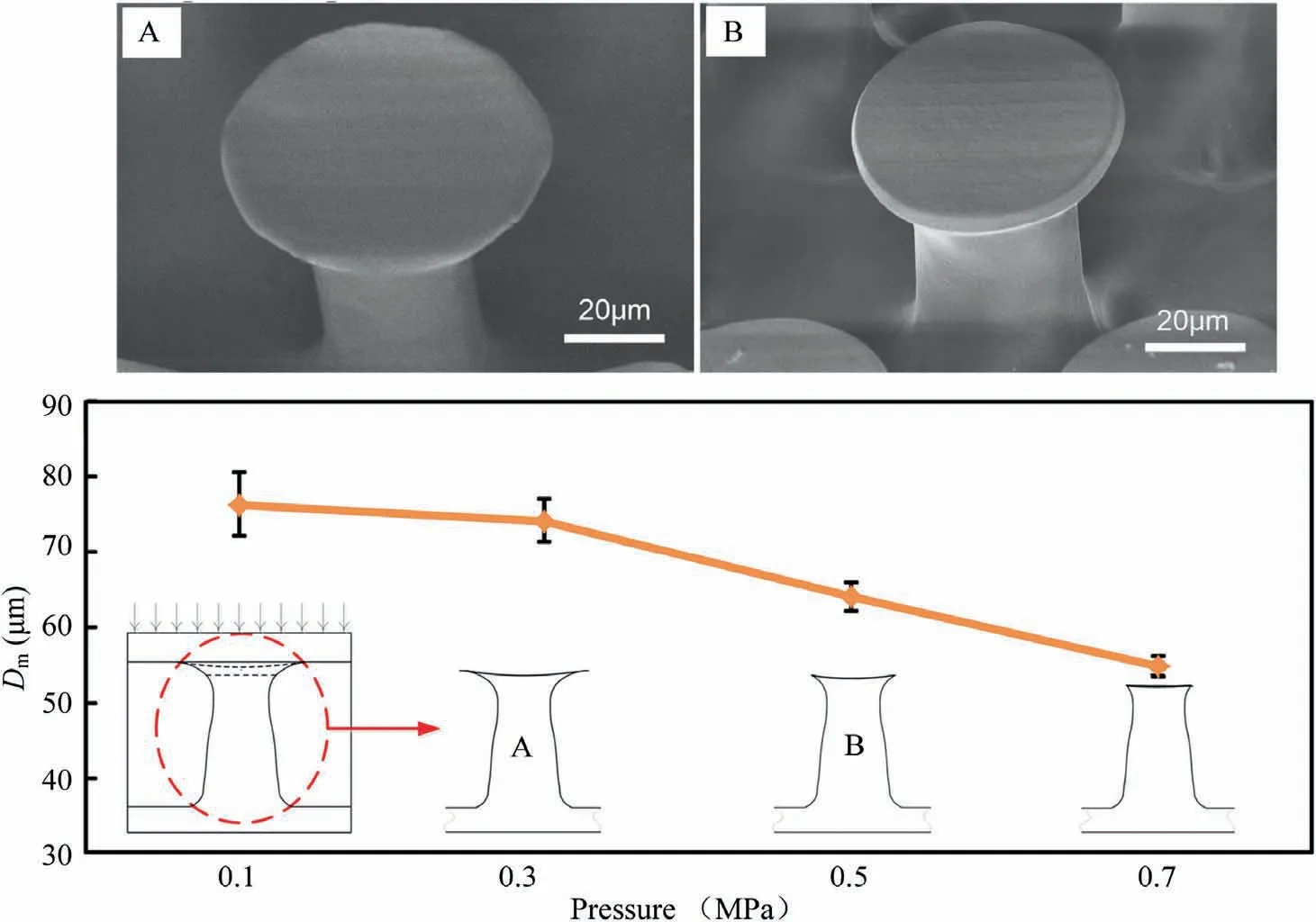
Fig.4 SEM images of microstructure produces at pressures of 0.3 and 0.5 MPa(top)and effect of different pressures on morphology of tip.
3.2. Factors influencing microstructural morphology of bionic adhesives
In the manufacturing bionic adhesives with tip-expanded microstructural arrays by metal mold, the microstructural shape depends on the through-hole shape of the metal template on the one hand,and the deformation of the elastic cushion on the other. The metal template influences the microstructural morphology mainly through D, which is affected by the plating time. When Dor His determined,an excessively low Dcan lead to microstructural agglomeration, collapse, and even fracture during demolding.Therefore, in this experiment, the metal template with a 1 h plating modification was selected to make the adhesive material and study the effect of the pressure on the microstructural morphology.
When the metal template and elastic cushion are closely fitted, the elastic cushion under pressure will inevitably produce small deformations, which will cause changes in the cavity,eventually affecting the shape of the expanded tip.Fig.4 shows the Dvalues of the microstructures made from the metal template plating modified for 1 h with pressures of 0.1, 0.3, 0.5,and 0.7 MPa, and a SEM image of a single microstructural unit with pressures of 0.3 and 0.5 MPa. It can be seen that,as the pressure increases, Dof the microstructure decreases,and when the pressure reaches 0.7 MPa, Ddecreases below 60 μm and the expanded tip of the microstructure almost disappears. From the SEM image of the microstructural unit, it can be also seen that the surface of the expanded tip is not flat,but rather spherical with a certain depth of depression. The above-mentioned experimental results fully indicate that the small deformation of the template plays a decisive role in the shape of the replicated microstructure. By adjusting the pressure between the metal template and the elastic cushion, the shape of the microstructure can be adjusted, especially the diameter of the expanded tip.
3.3. Dry adhesion test
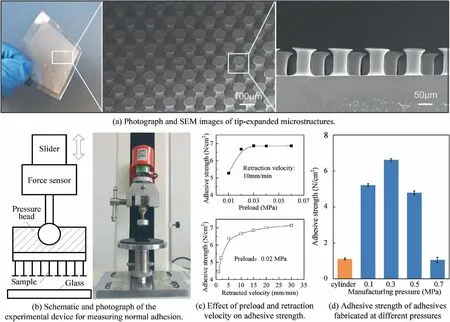
Fig. 5 Bionic adhesives with tip-expanded microstructural arrays produced by a metal mold and adhesion test results.
To test the adhesion properties of the bionic adhesives manufactured at different pressures, laboratory-fabricated samples were tested for normal adhesion using the previously described adhesion test method.Fig.5(a)shows a sample with an area of 30 mm×30 mm made from a modified metal mold. The height of the microstructure is approximately 100 μm, the rod diameter is approximately 50 μm, Dis 55-80 μm (depending on the pressure), and the adjacent microstructures are spaced at approximately 130 μm. The surface roughness of the top surface of the pillars is approximately 0.18 μm.Fig. 5(b) shows the force measuring device which mainly consists of a moving slide,pressure head,load table,and force sensor (range of 0-20 N with force resolution of 0.001 N and displacement resolution of 0.01 mm). To reduce the adverse effects on the adhesion test results due to the non-parallel surface of the press head, we designed a press head with a spherical hinge. This multi-degree of freedom press head was adaptively adjusted to ensure a more uniform distribution of forces on the adhesion surface during the test, thus reducing test errors.Fig.5(c)shows the effect of preload and retraction velocity on the adhesive strength.It can be seen that a preload within 0.02 MPa has a greater impact on the adhesive strength,while the effect reduces beyond this value. Because the actual contact area that can be reached is fixed as the retracted velocity increases, the adhesive strength shows an increasing trend.This is in agreement with the findings of Castellanosand Abusomwan. Fig. 5(d) shows the normal adhesion of the samples made using metal molds with plates modified for 1 h at different pressures; the yellow bar in Fig. 5d indicates the normal adhesion of samples made using cylindrical throughhole molds without plate modification. From Fig. 5(d), it can be seen that the range of adhesive strength of the samples made from the modified mold is 0.833-6.667 N/cm, which is significantly higher than that of the sample made from the unmodified mold;in particular,that made at the 0.3 MPa pressure is more than four times higher than that made with the unmodified mold. This suggests that the expansion tips contribute to improved adhesion performance,which is consistent with the results of several previous studies. This is mainly because expansion tips not only increase the effective contact area, but also improve the distribution of the contact stress at the adhesion interface.The significant differences in the adhesion properties of the tip-expanded microstructures prepared under different pressures also fully illustrate that the adhesion properties are very sensitive to the shape of the tips, so the process of manufacturing bionic adhesives with tip-expanded microstructural arrays by metal mold should control the pressure strictly.A smaller pressure leads to a smaller deformation of the elastic cushion,allowing the production of a larger tip-expanded tip for a certain area of the bionic adhesives, i.e., a larger effective contact area. As a result, a higher adhesion should be obtained.The adhesion of the samples made with pressures of 0.3-0.7 MPa supports this conclusion. However, the adhesion of the samples made with a 0.1 MPa pressure is lower than that of the samples made with a 0.3 MPa pressure, probably because the deformation of the elastic cushion by different pressures causes the tip of the microstructure to produce a small depression of different depths; this results in a different vacuum adsorption effect at the contact interface, ultimately resulting in differences in the macroscopic adhesion force. It has been experimentally demonstrated that the adhesion of bionic adhesives with tipexpanded microstructural arrays depends on partial vacuum adsorption forces as well as Van der Waals interactions.Moreover, some scholars have theoretically predicted that the vacuum adsorption effect is related to the tip morphology.
4. Conclusions
We developed a method for fabricating a metal template for bionic adhesives with tip-expanded microstructural arrays. In addition, the technique for manufacturing bionic adhesives with tip-expanded microstructural arrays by metal mold is introduced. The non-uniform distribution of the local current density and electrolyte concentration during the plating process is considered to fabricate microstructure metal molds with end-expansion based on the array of microporous metals; the plating time was adjusted to control the non-uniform evolution of through-holes to ensure the smooth release of endexpansion microstructures and avoid collapse. The small deformation of the elastic cushion under pressure affected the tip diameter of the microstructure, and the control of the pressure could improve the adhesion performance of the bionic adhesives. The adhesion test results successfully proved that the proposed methodology for the metal mold manufacturing of bionic adhesives with tip-expanded microstructural arrays is feasible. This method solved the issues of low wear resistance,vulnerability to high temperature, and scalability of the conventional mold manufacturing method. The proposed method may accelerate the large-scale application of bionic adhesives with tip-expanded microstructural arrays.
Declaration of Competing Interest
The authors declare that they have no known competing financial interests or personal relationships that could have appeared to influence the work reported in this paper.
Acknowledgement
sThis work was supported by the Natural Science Foundation of Jiangsu Province of China (No. BK20170796), the foundation of ‘‘Jiangsu Provincial Key Laboratory of Bionic Functional Materials” of China (No. NJ2020026), the foundation of National Defense Key Laboratory of China (No.6142004190204), and the National Natural Science Foundation of China (No. 52075249).
 CHINESE JOURNAL OF AERONAUTICS2021年4期
- CHINESE JOURNAL OF AERONAUTICS的其它文章
- Time delay compensation in lateral-directional flight control systems at high angles of attack
- Dual stability enhancement mechanisms of axial-slot casing treatment in a high-speed mixed-flow compressor with various tip clearances
- Development cost prediction of general aviation aircraft using combined estimation technique
- Improvement on shaped-hole film cooling effectiveness by integrating upstream sand-dune-shaped ramps
- Modeling and parameter identification of linear time-varying systems based on adaptive chirplet transform under random excitation
- An experimental method to obtain the hard alpha anomaly distribution for titanium alloy aeroengine disks
