Effect of the protrusion shape on gas ingestion of two sealing structures
Zeyu WU, Xing LUO,b,*, Jinqin ZHU,b, Hng CHEN, Jihu LIU
a School of Energy and Power Engineering, Beihang University, Beijing 100083, China
b National Key Laboratory of Science and Technology on Aero-Engine Aero-Thermodynamics, Beihang University, Beijing 100083, China Received 29 November 2019; revised 5 January 2020; accepted 8 February 2020
KEYWORDS Axial seal;Cavity;Gas ingestion;Protrusion shape;Radial seal;Sealing efficiency;Turbine
Abstract The windage loss caused by protrusion in a rotor-stator cavity has been studied in detail,and there are abundant fitting formulas that have been summarized to calculate the moment coefficients. Some other theorists have emphasized its effect on the sealing efficiency, proposing that installation of protrusion could alleviate gas ingestion. However, the protrusion shape which is an influential factor on the sealing efficiency has not been focused in previous research. Using the experimental method of measuring CO2 volume fraction,cavity pressure,and power consumption,we investigated the effects of several typical protrusion shapes on various parameters for two sealing structures,in order to obtain the optimal shape.Results showed that a variation of the protrusion shape had little impact on the static pressure,but the total pressure and the sealing efficiency increased in different degrees.Furthermore, even though the hexagon shape resulted in the highest sealing efficiency, we observed that the drop shape had the best overall performance in all of the eight models, which could result in higher efficiency of the turbine cavity. The combination of a radial seal structure and protrusion could improve sealing efficiency better.
1. Introduction
Bolts with different shapes, whose influences are complex and changeable, are common structures in a turbine cavity. The main part of a turbine cavity structure is a rotor-stator system.The efficiency of a turbine is highly significant to an aeroengine, and the variety of sealing efficiency caused by gas ingestion is very important in this regard.
In the field of gas ingestion, Owen at Bath University has done a lot of basic research and put forward the method of theoretical analysis. Owenproposed an orifice model for gas ingestion. The orifice model divides gas ingestion into rotating induced ingress, externally induced ingress, and combined ingress. Thenceforth, researchers continued to supplement the orifice model of Owen through different means.Balasubramanian et al.used experimental methods to measure the pressure and concentration of a radial rim seal, and obtained the variation laws of the ingestion and outflow coefficients. Johnson et al.performed a three-dimensional transient numerical simulation of a 1.5-stage turbine, and simulation results were in good agreement with experimental ones. Zhou et al.obtained the number of measuring points for sealing efficiency that needed to be known to obtain the minimum sealed flow rate by maximum likelihood estimation. Graber et al.used carbon dioxide as a tracer gas to study the sealing efficiency of a cavity. Experimental results showed that the influence of outflow pre-swirling on the sealing efficiency could be neglected, while the rotational speed of the rotor and the clearance of the sealing ring affected the sealing efficiency.
The understanding of externally induced ingress was based on the complex flow of the mainstream caused by the interaction between vanes and blades, which deteriorated the sealing efficiency. In terms of experiments, Dring et al.and others began to use the method of pressure measurement to study the influences of vanes and blades on gas ingestion.Bohn et al.found that blades would cause an increase of the mainstream circumferential pressure difference, but whether it would lead to increased ingestion depended on different sealing structures.Roy et al.found that the presence of vanes and blades caused periodic fluctuations in the mainstream pressure, while the pressure inside the cavity was uniform in the circumferential direction. Zhou et al.used Particle Image Velocimetry(PIV) to measure the flow field near a seal ring. Experimental results showed that there was a high radial velocity when gas ingestion occurred. In terms of numerical simulation, Hills et al.replaced a blade with a cylinder, and found that the addition of the cylinder exacerbated gas ingestion. Gentilhomme et al.studied the causes of uneven circumferential pressure near a mainstream sealing ring by numerical simulation. It was found that the circumferential unevenness of the mainstream pressure was mainly caused by the guide vanes.Wang et al.found that the most serious gas ingestion occurred at the position where the sealing ring was close to the vane. Mirzamoghadam et al.compared the effects of vanes and blades on gas by numerical simulation. Results showed that the influence of vanes on gas ingestion was dominant.
In the research of gas ingestion, researchers not only study gas ingestion through various experimental and numerical simulation methods, but also consider reducing gas ingestion and improving the sealing efficiency by continuously improving the design of the cavity structure. The research of Choi et al.showed that a sealing structure with an axial jet at the high position of the stator could block the mainstream gas, and its sealing effect was better than that of a usual sealing structure. Moon et al.found through numerical simulation that creating a small cavity of a suitable size in the sealing clearance helped to reduce gas ingestion. Okita et al.found that the design of the web could greatly reduce the influence of ingress on the rotor and improve the cooling efficiency of the cavity through experimental and numerical research. Sangan et al.experimentally studied the effect of a rotor seal ring with ribs on gas ingestion, and experimental results showed that the sealing ring with ribs installed had a higher sealing efficiency.Luo et al.systematically studied the wind resistance and temperature rise characteristics in a rotor-stator cavity, and summed up a lot of practical empirical formulas for various situations that install protrusions.Liu et al.creatively drew a key factor that could measure the degree of gas intrusion in a cavity with protrusions, and in a follow-up study, they compared the effects of some protrusion parameters on gas ingestion in the cavity. Chen et al.investigated the influence of after-damage clearance and tooth bending length on the leakage performance and rotordynamic coefficients of labyrinth seals. Caoand Wuet al. studied the effect of rotormounted protrusion on sealing performance.
It can be concluded that predecessors have prolific research results on gas ingestion mechanism and sealing structure design. Moreover, the effects of some protrusion parameters on turbine efficiency have get some results. However, there is a lack of more systematic exploration of the protrusion shape.The aim of current research was to estimate the role of protrusion shape in gas ingestion by conducting a contrast experiment. Based on experimental results, an evaluation parameter was proposed to obtain the optimal shape of protrusion. Static pressure, tangential velocity, concentrations of tracer particles(carbon dioxide),and power consumption were measured in the experiment.During the experiment,the annulus Reynolds number (Re) was set at 4.39×10, and the rotating Reynolds number (Re) was from 9.01×10to 1.20×10, while the dimensionless sealing air flow rate (C)ranged from 3878 to 8331. Details will be introduced and discussed in the following sections.
2. Equipment and methods
This study adopted methods of measuring COvolume fraction, cavity pressure, and power consumption. The objective of this experiment was to identify the effects of several typical protrusion shapes on various parameters and obtain the optimal shape. The experimental apparatus mainly consists of a flow and auxiliary system, a cavity structure system, and a measurement and recording system. Aluminum alloys were selected as the material of the core components, whose design speed was 3000 r/min. This study was conducted at the National Key Laboratory of Science and Technology on Aero-Engine Aero-Thermodynamics located in the School of Energy and Power Engineering at Beihang University.
This experiment used a method of mass transfer instead of heat transfer.Therefore,when the heat exchange was not studied, the experiment was conducted at normal temperature. At the same time,for the difference of the rotating Reynolds number, the dimensionless turbulence parameter λ=C/Rewas selected to ensure that the experimental conditions were similar to real conditions. According to the orifice model proposed by Owen,the leakage amount is more dependent on the pressure difference between inside and outside the rim seal.Therefore, the experiment mainly controlled the pressure difference between the rotating cavity and the main flow to simulate the actual conditions.
To begin this process,the annulus flow and sealing air were started respectively. Next, the rotating speed was adjusted to the predetermined parameters, and trace particles were added into the sealing air.The last step was to open the measurement program and record pressure and concentration data sequentially. The overall arrangement of the experimental apparatus is shown in Fig.1.The following is a brief introduction of each system.
2.1. Flow and auxiliary system
Pumped by a centrifugal fan, the annulus flow coming from the surrounding air passed the vanes and the blades in sequence after going through the inlet section. At the same time,the sealing air supplied by the compressor was added into the lower position of the cavity,then flowed out from the sealing ring, and mixed with the annulus flow. The height of the channel near the rim seal was designed as 20 mm. Two airflows, whose maximum flow rate were 15000 kg/h and 350 kg/h respectively,were eventually discharged from the passage behind the blades. Before the sealing air entered the cavity, tracer particles, carbon dioxide, were attached to it, of which the concentration was stabilized at three percent. In order to convert the operating conditions, a valve and a cooling box were prepared to regulate the sealing flow.Air at each radial position in the cavity was sampled to measure COconcentrations which could be utilized to calculate the sealing efficiency.
2.2. Cavity structure system
The longitudinal sectional view of the cavity structure system is demonstrated in Fig. 2. The left side of the figure is the stator,and the right side is the rotor.A total of 67 blades and 40 vanes were assembled on the rotor and the stator,respectively.A radial rim seal whose clearance was maintained at 2 mm was adopted to eliminate the ingress. At the center of the cavity,sealing air flowed in through the inlet from the side of the static disk,and the inlet channel height H was also 20 mm.As shown in Fig. 2, the radial sealing structure has teeth on the rotor,while the axial sealing structure has no teeth.
As can be seen in Fig.2,the rectangle on the rotor was the protrusion which was positioned at the radial location of 0.884b. During the experiment, the amount of the protrusion was fixed at 12, while its height h and maximum diameter D were both 10 mm. There were six types of shape shown in Fig. 3 that were arranged for substitution.
Overall, the experiment utilized a total of three rotor models as a comparison. Model Ⅰwas a typical rotor-stator cavity without any protrusion. Model Ⅱcombined Model Ⅰand several shapes of protrusions. Model III was an exceptional case,which corresponded to the presence of a cover along the entire circumference. The latter two models were employed as the main testing objects. However, the first one was just a reference.A collection of three models with only 45°was exhibited in Fig. 4.
2.3. Measurement and recording system
Six parameters, i.e., flow rate, static pressure, total pressure,rotating speed, power consumption, and COconcentration,were required to be measured.
The flow rates of annulus flow and sealing flow were obtained by different techniques. A thermal mass flow meter was opted to gain the flow rate of the sealing air. FCI was the manufacturer of this instrument whose accuracy was 1%of the reading plus 0.5%of the full scale.Because the annulus flow came from the surrounding air, it could not be measured directly. Instead, it could be derived from the velocity and the annulus channel area.As for the area,it could be easily calculated. The velocity was acquired by a differential pressure transmitter called Rosemount, which got the static and total pressures by two types of pitot tubes inserted into the channel.
The same as the measurement of velocity, the static and total pressures which were the critical factors in the cavity were collected through Rosemount’s too. At the beginning of the experiment, all of the Rosemount’s would be calibrated in a standard wind tunnel. Their calibration ranges were 0-6.126 kPa, and the uncertainties of the velocity and the two types of pressure were less than±2%.
The rotating speed of the equipment was obtained by a photo-switch combined with a tachometer. The mean error of this measurement system was less than±7 r/min.
The energy consumption of the rotor with protrusion was measured by an MPT2200-A model DC power meter, whose accuracy was 0.5% of the range.
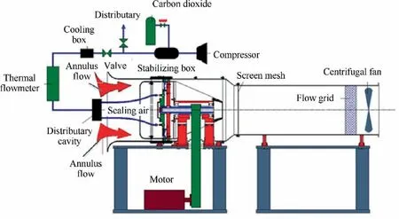
Fig. 1 Overall arrangement of experimental apparatus.
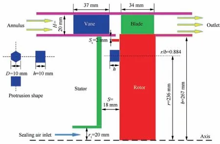
Fig. 2 Longitudinal section of overall configuration.
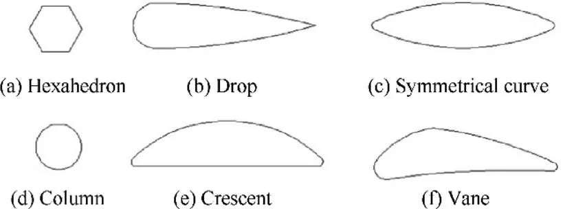
Fig. 3 Six kinds of protrusion shape.
In this experiment, the volumetric concentration of COin the sealing air was the most momentous parameter representing the sealing efficiency of the rotor-stator cavity. It was extracted by a COinfrared analyzer whose average error was not more than±2%FS(Full Scale).The measurement range which was 0-5% could meet the testing requirement. During the experiment, the sealing efficiency was calculated by three values of concentration which were being recorded by three infrared analyzers at the same time respectively. The first analyzer was responsible for the concentration Cin the sealing flow, and the second one detected the value Cat the inlet of the annulus channel. Finally, the last instrument was utilized to successively monitor the fluctuation of the concentration C at 10 radial points in the cavity. Then it was simple to compute the sealing efficiency (ε) by using the following equation:

In the course of experiment,the value ε increased from zero to one with an increase of the sealing air. It was believed that gas ingestion did not occur when ε raised to 0.99. At this moment, the corresponding sealing flow was the minimum sealing flow of this operating condition.
All kinds of measurement points in the cavity were arranged as shown in Fig. 5.
The recording system consisted of Adam, a computer, and the corresponding processing program. Data gotten from those instruments were collected through Adam and transmitted to the computer. Results were generated and saved by a special processing program in real time.
3. Experimental results and discussion
As outlined earlier, the concentration data, pressure, and power consumption were the vital parameters that controlled the condition of the cavity.Using the aforementioned method,we could investigate the characteristics of these parameters.Eventually, experimental results would be further discussed to estimate the optimal shape in all cases.
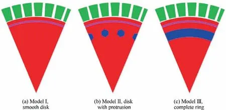
Fig. 4 Structures of three models tested in the experiment (taking the radial sealing structure as an example).
3.1. Impact of protrusion shape on cavity
3.1.1. Impact of protrusion shape on sealing efficiency
The radial sealing efficiency distributions of different protrusion shapes of the two sealing structures are shown in Fig. 6.Since the outcomes of the radial distributions are similar,only half results of the rotational Reynolds number of 1.05×10are selected for display.The range of the dimensionless sealing flow Cin the figure is 3500-8500.
It can be clearly seen from the figure that with an increase of the dimensionless sealing air flow rate,the sealing efficiency inside the cavity would also increase as a whole.In the case of a low sealing flow, the sealing efficiency at a high radius was obviously reduced,while in a high sealing flow,the sealing efficiency in the cavity tended to be uniform. Compared with the radial sealing structure, although the sealing efficiencies of the two seals were similar in the radial distribution, the sealing flow required for the axial sealing structure to achieve sealing was significantly higher.
Fig. 7 shows the effect of the protrusion shape on the sealing efficiency when the annulus Reynolds number was 4.39×10and the rotational Reynolds number was from 9.01×10to 1.20×10. In the experiment, the sealing efficiency of r/b=0.978 indicated the sealing efficiency of the whole cavity.When the sealing efficiency measured by the concentration method reached 0.99, it was considered that no gas intrusion occurred at this time. Main conclusions about the concentration data of the two sealing structures are as follows.
As can be seen from the figure, the impacts of changes in the shape of protrusion and the flow rate of the sealing air on the sealing efficiency are very obvious. When the external condition and the protrusion shape did not change, with an increase of the sealing air, the sealing efficiency of the cavity would be obviously improved until the cavity was sealed.For the same flow rate of the sealing air, when the protrusion shape was hexahedron, column, or drop, the sealing efficiency within the cavity would have a relatively large increase. However, when the protrusion shape was crescent, vane, or symmetrical curve, we could only see a slight increase. When the shape became complete ring,the sealing efficiency of the cavity was basically consistent with that of the smooth disk, which was lower than that of any other experimental group.Overall,the sealing efficiency of the radial seal was higher, but protrusions improved the sealing efficiency more for the axial structure.
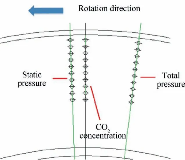
Fig. 5 Measurement points in cavity.
3.1.2. Impact of protrusion shape on pressure
In the context of experimental conditions, under the same rotational Reynolds number and sealing flow, as the shape of protrusion varied, the static pressure P in the cavity would be reduced, except for the pressure point closest to the seal.Meanwhile, on the whole, the static pressure increased as the radius increased. While at the position where the protrusion was located, the static pressure would increase a little more.For the shapes of hexahedron and drop, the pressure near the seal was higher than that of the smooth disk. The static pressure reduction of the axial seal structure was slightly more than that of the radial seal structure after the installation of the protrusion. The specific data is shown in Fig. 8.
In Fig. 9, we presented the experimental outcome of the total pressure Pwhen the protrusion was fixed on the rotor.Contrary to the results of the static pressure, the diverse protrusion brought a considerable variation for the total pressure in general.It is apparent that the protrusion contributed to the overall augmentation of the total pressure. However, its increasing extent in the direction of the radius was different.The larger the radius, the more it increased. At the position where the protrusion was located, it could also be observed that the total pressure was enlarged.The increment of the total pressure would vary with the shape of protrusion.The increase in the total pressure was greatly affected by the rotating speed.At the same rotational Reynolds number,the total pressures of the two structures were relatively close.
3.1.3. Impact of protrusion shape on power consumption
Fig. 10 shows the power consumption (W) data for different protrusion shapes. The power consumption data trends of the two structures were consistent.It can be seen from the figure that an increase in the rotating Reynolds number played a major role in the power increase. As the rotating Reynolds number increased, the difference between the rotor with protrusions and the smooth disk would increase too. At the same time, the power consumptions under different protrusion shapes were significantly different. The cover could effectively reduce the power consumption,and the two without the cover consumed more power.
3.2. Further discussion
3.2.1. Impact of protrusion shape on flow structure
The influence of protrusion on the flow field was mainly reflected in the work process of the rotating disc on the fluid micro-clusters. The protrusion rotated at high speed with the rotor and struck the low-speed fluid in the rotating core at the same radial position. The hit caused the protrusion windward and leeward to form local high- and low-pressure zones,respectively. For the impacted fluid micro-clusters, they got higher tangential velocity and were also squeezed into the high radial position by protrusion. This process was accompanied by a large number of horseshoe vortices, and the interaction between the vortices reduced the static pressure in the cavity,which was also consistent with the static pressure data obtained previously.
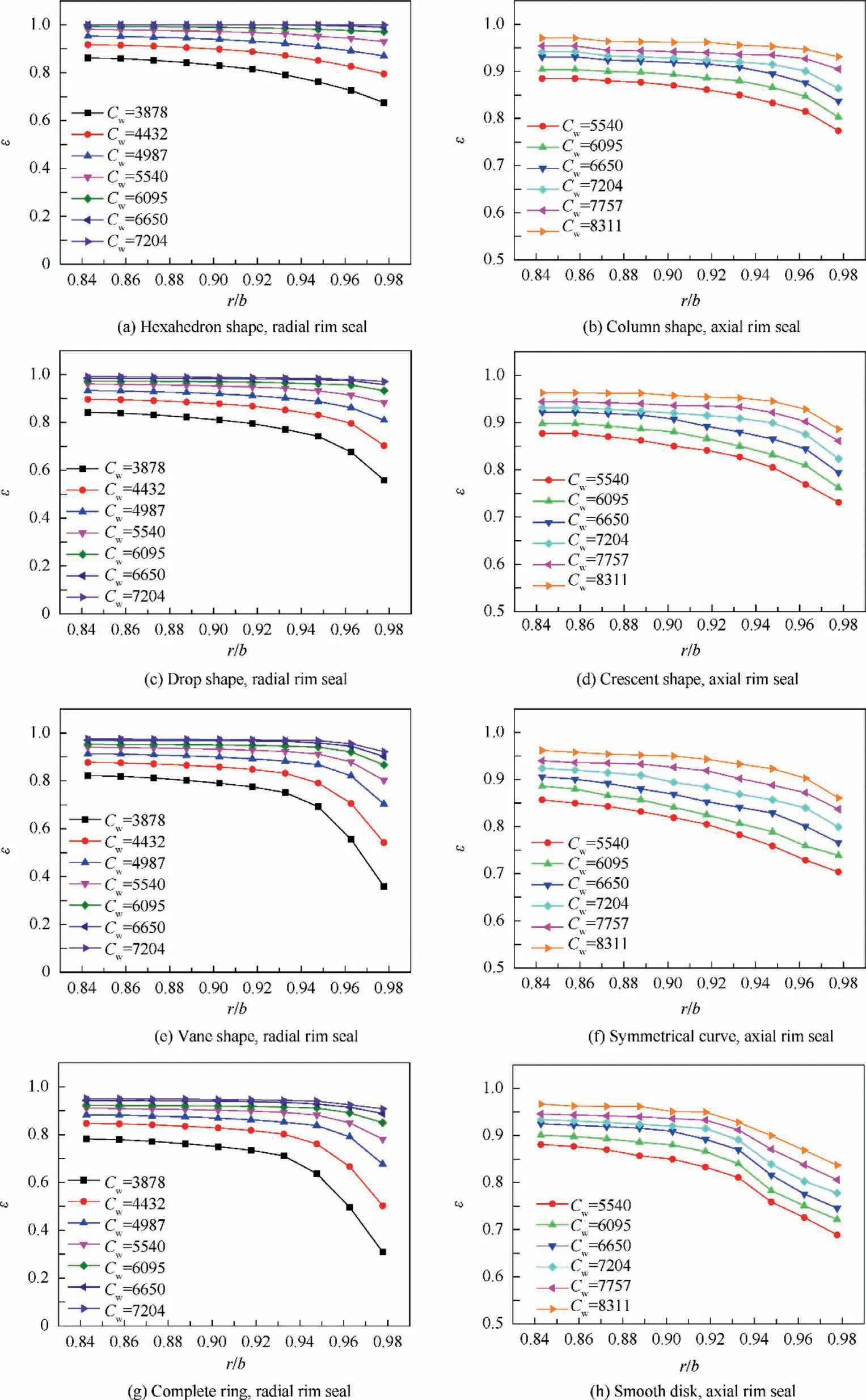
Fig. 6 Variations of radial sealing efficiency for different shapes of protrusion (Rew=4.39×10⁵, ReΦ=1.05×10⁶).
From the above analysis, it can be seen that the impact of the protrusion on the sealing efficiency was due to its work on the fluid and the loss caused by this process.The work and loss caused by different shapes of protrusion were different.Therefore, the increases of the total pressure and the power consumption would be different. Comparing the total pressure data of different structures, it can be found that the hexahedron, column, and drop shapes had larger windward areas and resulted in higher total pressure. Therefore, the final sealing efficiency was also significantly higher than that of the sharp angle windward. Observing the power consumption data, it can be seen that the power consumptions of the first two protrusions were significantly higher than those of the other four protrusions. Therefore, a reasonable design of the extension section could effectively reduce the loss of the leeward area and the overall power consumption.
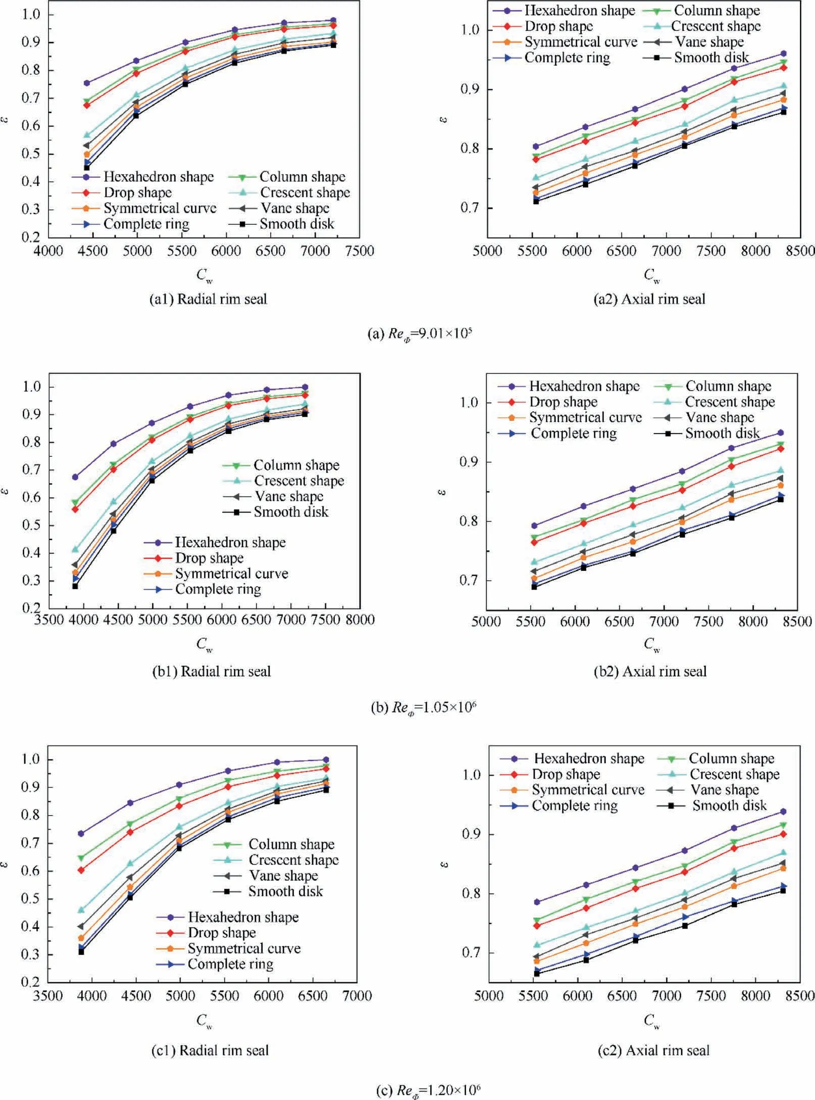
Fig. 7 Variations of sealing efficiency with sealing flow for different shapes of protrusion (Rew=4.39×10⁵).
The swirl ratio β distributions of the two sealing structures are shown in Fig. 11. As can be seen from the figure, the flow in the cavity was mainly dominated by rotation. For the smooth disk,the swirl ratio exhibited a monotonically increasing linear distribution along the radial direction.For the experimental group with the protrusions installed, the swirl ratio in the cavity rose as a whole. At the same time, there was a local maximum at the radial position of protrusion installation.This phenomenon was also consistent with the flow field analysis mentioned above.It can be seen that the most obvious change was the hexahedron structure.It is believed that the flow structure of the cavity with protrusion is also Batchelor flow, but with a more complex vortex system. The swirl ratio distributions of the two structures were similar overall and had little change with the rotating Reynolds number.
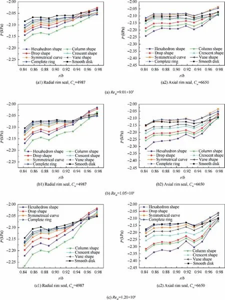
Fig. 8 Radial distributions of static pressure for different shapes of protrusion (Rew=4.39×10⁵).
3.2.2. The minimum sealing flow rate
The sealing efficiency curves of different protrusion shapes were fitted respectively. When the efficiency was equal to 0.99, the corresponding dimensionless sealing flow was the minimum sealing flow under this condition.Results are shown in Fig.12.It can be seen from the figure that the trends of the minimum sealing flows of the two sealing structures were different. For radial structures, the larger the Reynolds number,the lower the minimum sealing flow required. The case of the axial structure was reversed.This was mainly due to the different flow fields of the two sealed structures. On one hand, the minimum sealing flow of the radial structure was lower overall.On the other hand, the effect of the protrusion on the minimum sealing flow was basically the same,and with an increase of the rotational speed, the improvement became more apparent. It can be seen that in the process of shape changes, the minimum sealing flow in the cavity changed too, and its minimum value appeared when the shape was hexahedron.
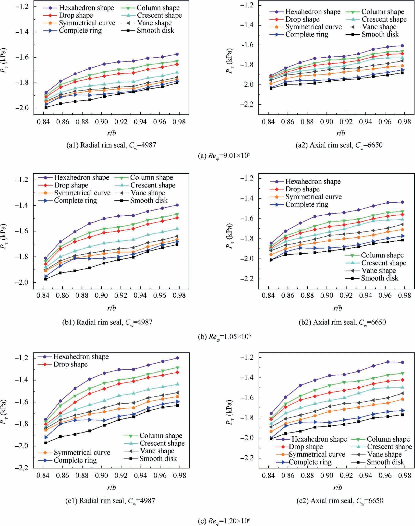
Fig. 9 Radial distributions of total pressure for different shapes of protrusion (Rew=4.39×10⁵).
3.2.3. The best shape of protrusion
On one hand, the protrusion increased the swirling coefficient by affecting the flow field of the rotor-stator cavity,so that the sealing effect was better than that of the smooth disk,which is what a designer hopes. On the other hand, the installation of the protrusion also increased the windage of the rotor, and the power consumption of the shaft was also increased simultaneously.This is what we want to avoid.In order to maximize the benefits,it is necessary to compare the advantages and disadvantages of different shape protrusions. Thus, we can find the appropriate protrusion shape for both sealing structures.
Setting the smooth disc as a reference, Δε is the sealing efficiency difference between the rotor with protrusion and the smooth disk under the same working condition, and W/Wis the ratio of power consumptions between the protrusion disk and the smooth disk. A dimensionless evaluation parameter δ is defined to indicate whether one case is better than another case, as shown in Eq. (2). According to the definition of the following equation, the higher the value of δ,the better the effect of the corresponding shape. It comprehensively considers the levels of the efficiency improvement and the power consumption. Under different shapes of protrusion, the changes of δ for two sealing structures are shown in Fig. 13.
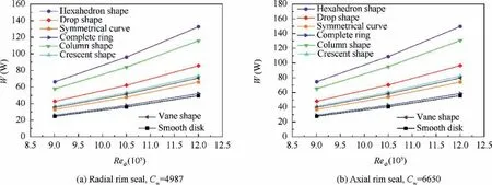
Fig. 10 Power consumptions for different shapes of protrusion (Rew=4.39×10⁵).
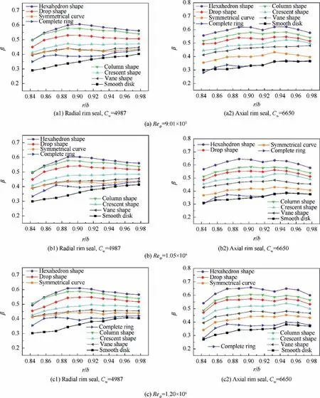
Fig. 11 Swirl ratio inside the cavity with rotor-mounted protrusions (Rew=4.39×10⁵).
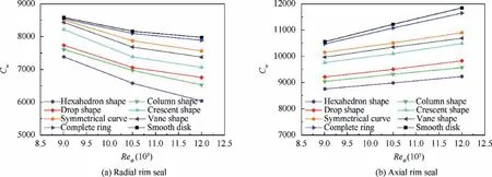
Fig. 12 The minimum sealing flows for different shapes of protrusion (Rew=4.39×10⁵).
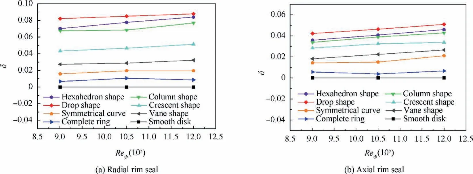
Fig. 13 δ for different shapes of protrusion (Rew=4.39×10⁵).

It can be seen from the figure that δ varied markedly with the shape of protrusion. The difference between the values of the complete ring and the control group was small.Three types of protrusions whose windward sides are sharp performed poorly, which was mainly due to this design having a limited effect on the improvement of the sealing efficiency. The three types of protrusions with blunt windward sides were better for both seals. However, because of an increase in the power consumption, the δ values of the hexahedron and column shapes decreased more. The best shape of protrusion was the drop shape, and this shape effectively took into account the balance between efficiency and power consumption. The drop shape was able to reduce the power consumption as much as possible while achieving higher sealing efficiency. On the whole, the combination of protrusion and the radial sealing structure was also superior to the axial structure under the same working condition.
4. Conclusions
In this paper, the effects of the protrusion shape on the efficiencies of two kinds of turbine cavity were investigated experimentally.
The impacts of the protrusion shape on static pressure,total pressure, power consumption, and sealing efficiency in the cavity were measured by an experimental method. Results showed that a change of the shape of protrusions had little effect on the static pressure in the cavity, and a static pressure change near the sealing ring was almost negligible.Meanwhile,the total pressure and the sealing efficiency would increase with a change of the protrusion shape. The highest total pressure and sealing efficiency were obtained when the shape was hexahedron. In addition, an increase in the rotating Reynolds number played a major role in the power increase.
In further discussion, considering the sealing efficiency and power consumption, the best shape of protrusion was drop.This kind of shape could optimally balance the alleviation of gas ingestion and the reduction of power consumption. It is concluded that a proper shape of protrusion would lead to less windage loss and higher sealing efficiency at the same time and result in high efficiency of a turbine cavity.The drop shape was a good solution for this problem. The sealing effect and promotion after installed protrusion of a radial sealing structure were better than those of an axial sealing structure.Therefore,the comprehensive design of a protrusion shape and a sealing structure could improve the sealing efficiency better.
Declaration of Competing Interest
The authors declare that they have no known competing financial interests or personal relationships that could have appeared to influence the work reported in this paper.
 CHINESE JOURNAL OF AERONAUTICS2021年4期
- CHINESE JOURNAL OF AERONAUTICS的其它文章
- Time delay compensation in lateral-directional flight control systems at high angles of attack
- Dual stability enhancement mechanisms of axial-slot casing treatment in a high-speed mixed-flow compressor with various tip clearances
- Development cost prediction of general aviation aircraft using combined estimation technique
- Improvement on shaped-hole film cooling effectiveness by integrating upstream sand-dune-shaped ramps
- Modeling and parameter identification of linear time-varying systems based on adaptive chirplet transform under random excitation
- An experimental method to obtain the hard alpha anomaly distribution for titanium alloy aeroengine disks
