Deployment dynamics for flexible deployable primary mirror of space telescope with paraboloidal and laminated structure by using absolute node coordinate method
Bindi YOU, Dong LIANG, Xiangjie YU, Xiaolei WEN
School of Naval Architecture and Ocean Engineering, Harbin Institute of Technology, Weihai 264209, China
KEYWORDS Deployable space telescope;Deployment dynamics;Flexible deformation;Laminated mirror;Paraboloidal structure
Abstract A nonlinear dynamic modeling method for primary mirror of Flower-like Deployable Space Telescope(F-DST)undergoing large deployment motion is proposed in this paper.To ensure pointing accuracy and attitude stability of the paraboloidal primary mirror,the mirror is discretized into equal thickness shell elements by considering shell curvature. And the material nonlinear constitutive relation of flexible mirror is acquired using Absolute Nodal Coordinate Formulation(ANCF).Furthermore,the primary mirror of F-DST can be regarded as a clustered multi-body system, and its dynamic equations of elastic deformation and deployment motion are established by virtual work principle. Finally,the deployment motion of primary mirror by different driving conditions are simulated, the results show that the vibrations of mirrors that driven by elastic hinge device are more than that driven by servo motor.In addition,single sub-mirror deployment process will perturb the pointing accuracy of primary mirror, and the multiple sub-mirrors simultaneously deploying will seriously affect all the sub-mirrors surface accuracy because of the coupling effect.Thus, there are theoretical value and practical significance for the controlling surface accuracy and attitude accuracy of space telescope.
1. Introduction
Deployable space telescope is special prolonged observation equipment to observe space phenomena,and its imaging effect is affected by the surface and pointing accuracy of mirror.Firstly, the coupling of flexible deformation and rotational motion affect surface accuracy of mirror and deteriorate telescope observation results during the primary mirror deployment process. Secondly, the accuracy of dynamic equation will be affected by the characteristics of material and nonlinear structure of deployable space telescope. Thus, how to investigate the accuracy of the dynamic behaviors for flexible mirrors in the deployment process with considering above factors is the technological difficulties and challenges for analysis of flowerlike deployable space telescopes.
Hubble Telescope obtained the most observations results in human history, but it suffered malfunction due to vibration interference. Foster and Tinkerobserved thermal deformation from solar source interference by the representational process of vibration analysis and reduced the interference to the permissible range by optimizing the control-system algorithm.Duan et al.obtained the heat-coupling beam equation using Lagrange formulation, and analyzed structural response of solar panels. However, in these studies, the primary mirror was regarded as a rigid body, and the dynamic characteristics of the mirrors were not analyzed.Ijar et al.established a rigidflexible coupling satellite system model including a rigid satellite body and two rotating flexible solar panel. Then they analyzed the interaction between satellite attitude control and elastic deformation of solar panels. The elastic deformation of solar panels causes satellite attitude disturbance and it can be reduced by piezoelectric control. Therefore, the flexible appendages have an obvious effect on the attitude disturbance of satellite system.Accordingly,it is also necessary to consider the influence of flexible primary mirror on satellite.
An increase in the diameter of the telescope mirror is an effective method for obtaining better observation quality.Due to the limitation of rocket capacity, large aperture space telescope primary mirror is usually designed as a deployable structure with flexible laminated composites.However, there is strong coupling effect between different flexible sub-mirrors as flexible paraboloidal primary mirror deploying or large angle adjusting. In addition,the reflection accuracy and pointing accuracy of mirror are influenced by elastic deformation, that even lead to satellite failure. Tamer and Noorestablished a multi-body dynamics simulation system for the Next Generation Space Telescope(NGST) based on finite element analysis and fuzzy set control.They modeled super-elements for simulating the shell-like components of NGST by plate and truss structures. But mirrors are regarded as plate structure in this scheme without analyzing the deployment dynamics of telescope mirrors. Lin et al.presented a light-weighted mirror structure and analyzed its optical performance based on finite element method and optomechanical analysis. And they predicted the effect of mirror deformation on optical imaging performance by analyzing the primary mirror of Cassegrain telescope. Cheng et al.proposed an active adjustment platform for the primary mirror of segmented telescope that composed of the flexibility of the supporting leg and the actuator. They also analyzed the elastic deformation of the platform under external load,but they didn’t consider the effect of mirror flexible deformation characteristics on system stiffness.Zuo et al.designed a new type of Deployable Space Telescope (DST), and established the finite element model for the deployable structure to analyze deployment characteristics,but they ignored the flexibility of mirrors.Few scholars have paid enough attention to coupling dynamic behavior of flexible primary mirror of DST in the deployment process, and they were more focused on the primary mirror support or material characteristics.
The primary mirror of DST can be simplified to flexible laminated shell structure.Based on the first-order shear deformation theory,Guo et al.studied dynamic behavior of composite laminated doubly-curved shells by domain decomposition method. It explained the effect of external forces, geometric and material parameters on dynamic behavior.Hao and Kamused the Rayleigh-Ritz method to formulate the eigenvalue problem for determining the modal characteristics of the flexibly supported laminated composite plates,which accurately predicted dynamic behavior of flexibly supported laminated composite plates. Meanwhile, Liobtained accurate solutions to deformation of plate and the stress field between adjacent layers by a discontinuous finite element method. Shabana and Christensenfirst presented Absolute Nodal Coordinate Formulation (ANCF) for large deformation analysis of flexible multi-body systems. He verified equations of the large deformation and rotation motion of three-dimensional plate in absolute nodal coordinates, and obtained the mass matrix, which is constant, by describing the element coordinates of global displacement and gradient.Liu et al.presented the gradient-deficient cylindrical shell elements based on ANCF, they obtained the strain energy of the element and verify statics and dynamics equations by Green-Lagrange strain tensor in continuum mechanics. Yan et al.described the deformation energy of shell elements for ANCF by the strain tensor of Green-Lagrange,and they analyzed the gradient deficient shell elements to eliminate initial strain in the initial bending configuration. Based on ANCF, Abbas et al.developed three-dimensional variable thickness rectangular plate/shell elements by considering shear strain and transverse normal strain, and the accuracy of the model is verified by example analysis. These researches have laid foundation for the dynamic analysis of flexible plate and shell structure.However, they can’t accurately predict the dynamic system characteristics for neglect of its strong coupling nonlinear dynamics of the rotating space mechanisms with flexible appendages.Zhao et al.used the plate elements that described by ANCF to analyze a rotating thin plate,and the effect of rotating angular velocity and dimension parameters on the natural frequency of a thin plate is investigated.Meanwhile, the rigidflexible multi-body system model of large-scale rotating solar sail was established, and the dynamic equations of system deployment process was solved by the generalized method of α.
Xu et al.developed a dynamic model and a closed loop simulation system of spacecraft multi-body system including antenna reflector and solar panel,which provided a theoretical basis for the control of flexible structure. Liu et al.derived rigid-flexible-thermal coupling dynamic model of the spacecraft by considering the coupling effect among attitude motion, structural deformation and thermal loading. You et al.described the elastic deformation of paraboloidal flexible reflector,which considered the nonlinear strain and deformation relationship. Then, they deduced the nonlinear dynamics model of aerospace mechanism with thin shell structure and flexible appendages, and analyze the effect of coupling dynamics between the rigid body and the flexible appendages. In summary, few scholars study the coupling dynamics of the flexible multi-body system with flexible paraboloidal laminated shells at present. The primary mirror of DST belongs to laminated shell multi-body structure, which presents complex dynamic characteristics during deployment process and attitude adjustment. Shakouri and Kouchakzadehintroduced a method for analyzing the natural frequencies of generally shell structures under arbitrary boundary conditions, the effects of bending-stretching coupling, meridian arc length, shell thickness and layer angle of laminated material on shell structure were studied. These factors have important influence on the dynamic characteristics of shells and must be considered in practical modeling. Therefore,the coupling effect of elastic deformation and large angular motion in the laminated primary mirror system cannot be ignored.
In this paper, dynamic model of a flower-like deployable primary mirror is established for disturbance analysis of flexible mirrors and satellite attitude.First,flexible laminated paraboloidal mirrors are discretized into equal thickness shell elements by ANCF, and the constitutive relation of laminated mirrors is obtained considering shell curvature and the laminated material.Then,the dynamic equation of primary mirror in the deployment process is derived involving in the coupling effect of elastic deformation of the mirrors and large angle rotation by using the virtual work principle. Finally, different driving conditions and deployment strategies are simulated.The influences of different numbers of sub-mirrors simultaneous deploying on surface accuracy and attitude of the primary mirror are analyzed. Those provided a reference for deployment dynamic behavior of DST.
2. Deformation description of flexible mirrors
The structure of the primary mirror of F-DST is illustrated in Fig. 1. The image will be formed by incident ray through the reflection of large flexible paraboloidal primary mirror to secondary mirror, then to center primary mirror. In this paper,the deployable primary mirror is designed as flower-like,which is constituted by one center sub-mirror and eight surrounding sub-mirrors. Surrounding sub-mirrors are folded crosswise around the center sub-mirror, and they will deploy to a full paraboloidal primary mirror for on-orbit service.
The shell can be considered as plate element when it is divided into infinitesimally element. The paraboloidal thin shell element can be obtained by the rectangular plate elements that established by Mikkola and Shabanawith considering the characteristics of the laminated material and paraboloidal structure.The primary mirror can be divided into paraboloidal thin shell elements, and elastic deformation of it can be described by ANCF.As shown in Fig.2,at the initial moment,the area of one flexible mirror is B,the position vector of arbitrary point Pon the mirror is rin global coordinates. Flexible mirror will suffer elastic deformation in the deployment process. After deformation, the area Bof the flexible mirror becomes B,the point Pis redefined as P,and the position vector is r.
The displacement of point P can be written as
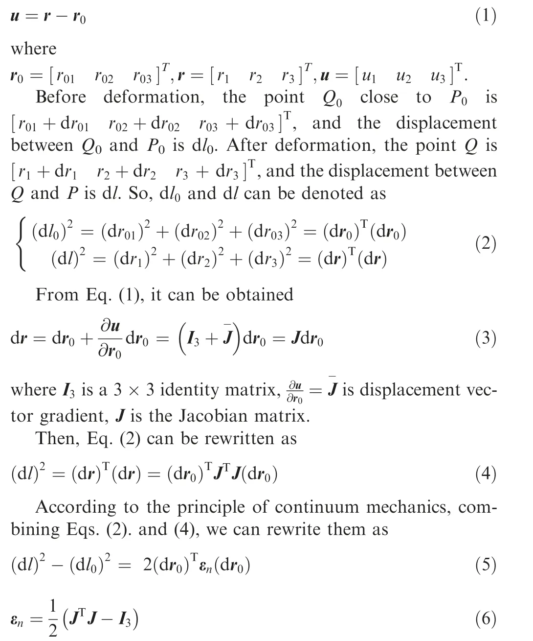
where εis a 3×3 matrix, which is Lagrange strain tensor.
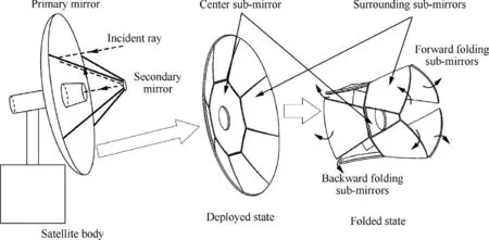
Fig. 1 Structure of primary mirror of F-DST.
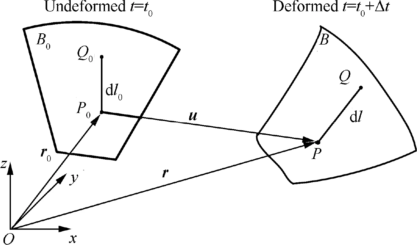
Fig. 2 Deformation of flexible mirror described by ANCF.
Space telescope mirror can be regarded as a flexible paraboloidal laminated shell structure, which is composed of anisotropic material. Laminated shell model that described by ANCF is shown in Fig. 3. The coordinate of laminated shell that along the meridian and circumferential directions of the middle surface is α and β,respectively.And the distance along the normal direction between each surfaces and middle surface is χ.Laminated mirrors can be divided into rectangular curved shell elements by finite element method,and the number of elements is n=n×n×n. The curved shell element of laminated shell model is shown in Fig. 4, the length, width and thickness are denoted as a,band h.Rand Rare curvature radius of meridian and circumferential,respectively.There are four nodes in the four corners of the neutral plane of curved shell element, which has been marked red in Fig. 4. The position vector of arbitrary point in the curved shell element can be described by the four nodes. The total thickness of thin shell made by nlayers of laminated material is defined as:
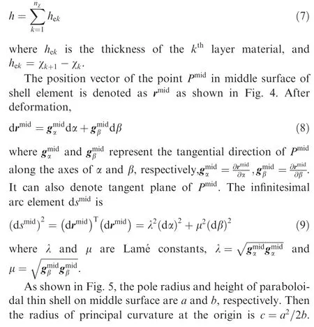
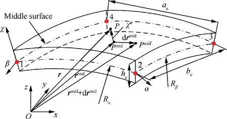
Fig. 4 Curved shell element of laminated shell model.
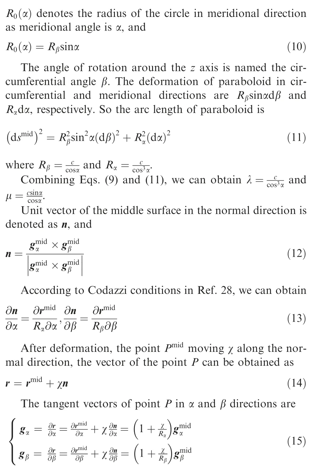
Corresponding to vector dr, we have the infinitesimal arc element ds

Fig. 3 Laminated shell model that described by ANCF.
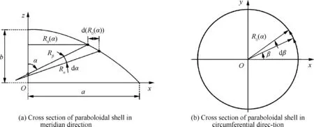
Fig. 5 Two kinds cross section of the paraboloidal shell.
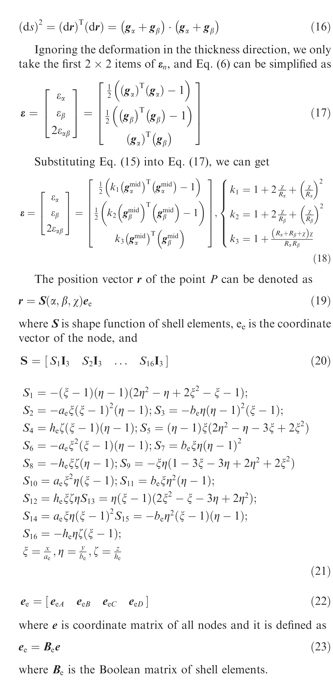
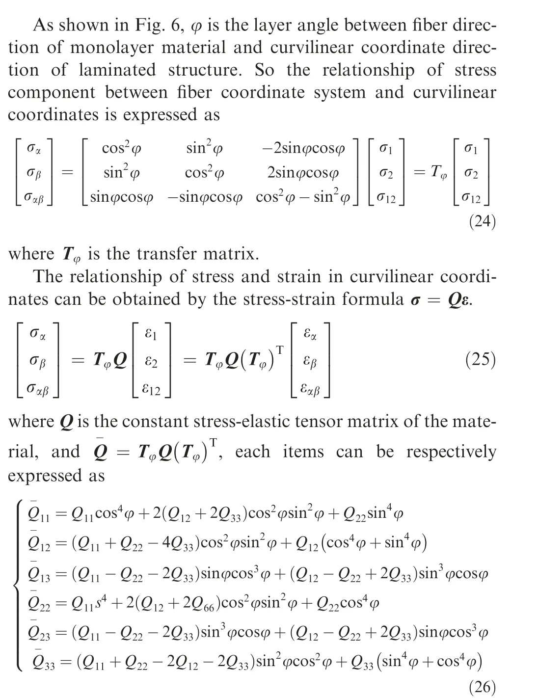
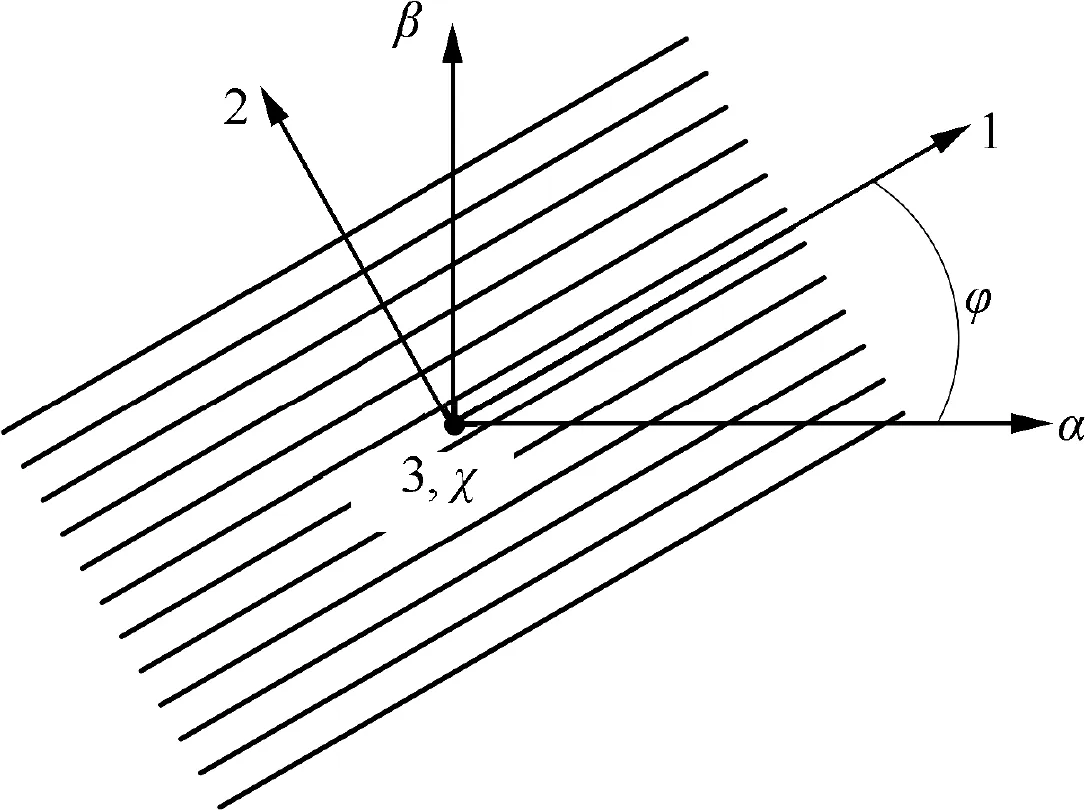
Fig. 6 Angle between fiber coordinate and curvilinear coordinate.

where σ, Qand ε are stress matrix, constant stiffness matrix and strain matrix,respectively,and the superscript k represents klayer.
3. Nonlinear dynamic equation of laminated mirrors in the deployment process
The position vector relationship of deployable primary mirror is shown in Fig. 7. The deployable primary mirror includes center sub-mirror and multiple surrounding sub-mirrors, and it can be regarded as a clustered multi-body system. In Fig.7,C is the center sub-mirror,and its motion can represent the motion of primary mirror, and its position vector is r.A(k=1,2,···,8) is denoted surrounding sub-mirrors and a position vector for them is r. jis the khinge between all sub-mirrors.
Then,the virtual work of inertial force of shell element can be expressed as
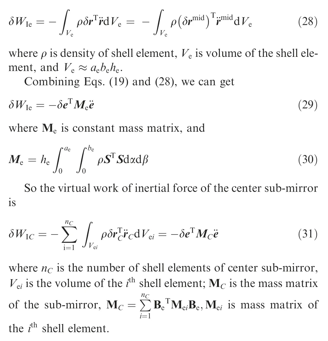
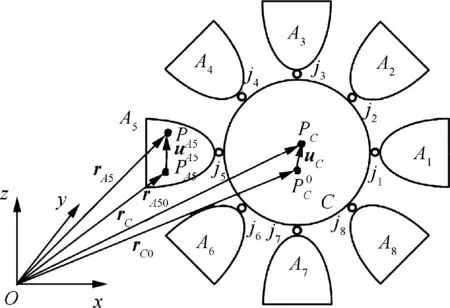
Fig. 7 Vector relationship of F-DST.
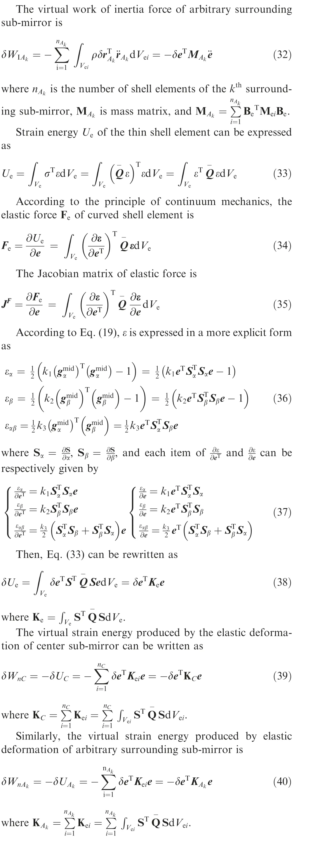
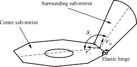
Fig. 8 Rotating elastic hinge device between surrounding submirrors and center sub-mirror.
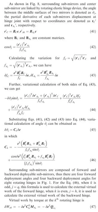
where Qis the generalized force matrix corresponding to the torque at rotating hinge, Q=-CM.
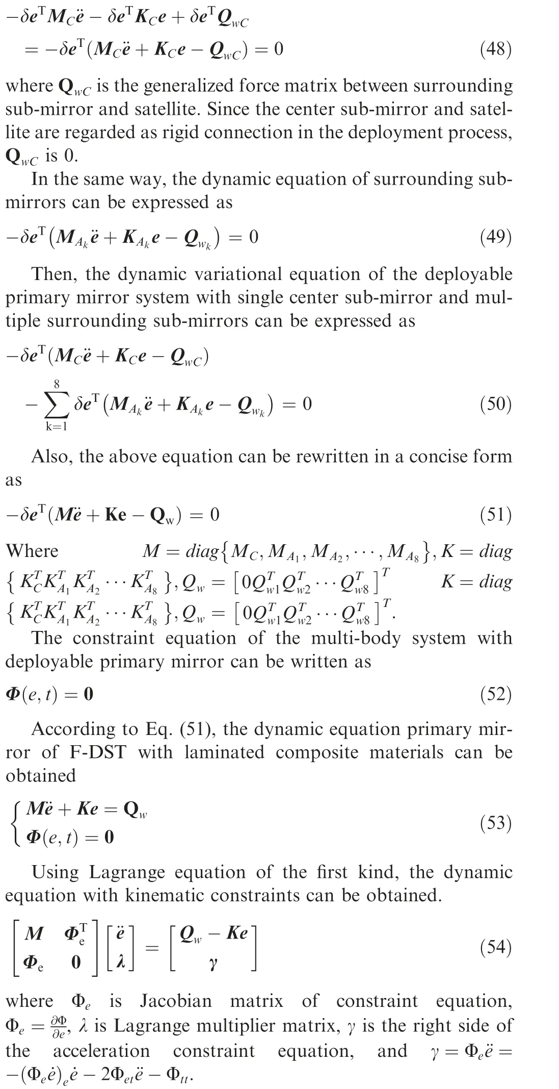
Substituting Eqs. (31), (39) and (47) into virtual work principle δW+δW+δW=0, the dynamic equation of center sub-mirror in the deployment process can be obtained as
4. Simulation analysis
Simulation model of F-DST is illustrated in Fig.9.Deployable primary mirror attaches to the satellite body by connecting shaft. After deployment, the radius of the primary mirror is 500.0 mm. The length of connecting shaft lis 400.0 mm.The satellite body can be simplified to a regular cube,and edge length is 100.0 mm.A rotating parabolic equation of the paraboloidal primary mirror can be written as
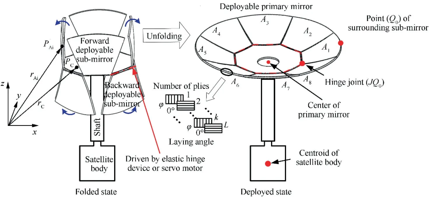
Fig. 9 Deployable primary mirror simulation model of space telescope.

The center sub-mirror is a regular octagon and its circumcircle diameter dis 350.0 mm. Deployment angle ϑof backward deployable sub-mirror is 85.0°. The mirrors are made of carbon fiber/epoxy resin composite (T300/5280), its density ρ=1650.0 kg/m, thickness of single layer his 0.125 mm,the number of plies L=16, the layer angle φ=90°. Other material properties are listed in Table.1.
4.1. Simulation analysis of deployment sub-mirrors under different driving conditions
In spacecraft mechanism,elastic hinge device and servo motor are common used to provide driving torques for deployment motion.In this section,the deployment motion of the primary mirror by elastic hinge device and servo motor are simulated,and their effects on the dynamic behavior of the primary mirror are analyzed respectively. Meanwhile, the joint hinges are assumed lubricated enough in this paper,so there are few frictions caused by the hinge joints in the deployment process.The main resistance sources of deployable primary mirror are damping torque of different driving conditions in the deployment process. Thus, the effect of friction can be ignored in comparison to the effect of damping torque of different driving conditions.
For elastic hinge device,the relationship of between driving torque and deployment angle is given by

where K is the elastic stiffness of the coil spring, K=30.0 N.mm.(°), Tis the damping torque, T=25.0 N.mm s(°),ϑand ϑare the deployment angle and the time-varyingdeployment angle, respectively, j=q and j=h represent the forward and backward mirrors, respectively.

Table 1 Carbon fiber/epoxy resin material properties.
In the other hand, driven by servo motor, the sub-mirror performs a rotational motion around its axis which is given as
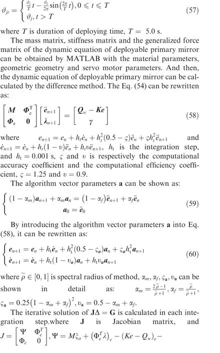

In the simulation process, the center sub-mirror is fixed,and the surrounding sub-mirrors are connected with center sub-mirror by rotating hinge.The movement angle of rotating hinge is 15.0(°)/s,the simulation time of each dynamic behavior analysis is defined as 10.0 s.
In order to verify the correctness of the model proposed in this paper,the present model based on ANCF-shell element is compared with the traditional Hybrid Coordinate Method and ANCF-plate element.The deformations of Qanalyzed by different methods in the deployment process are shown in Fig.10.Driven by spring hinge device,large deformation of sub-mirror is occurred in the initial stage, and then deformations gradually decrease with a small amplitude vibration.All three methods consistently reflect this phenomenon, and the results are similar. However, the convergence performance of the Hybrid Coordinate Method is not as good as that of the ANCF over time, which cannot accurately describe the deformation characteristics of flexible sub-mirrors. In addition, the ANCFplate element neglects the curvature of the shell(the curvature radius of meridian and circumferential Rand Rare considered as infinite value), which leads to a smaller strain and larger errors in the process of calculating deformations of flexible sub-mirrors. It can be seen that the present model considering the curvature of the shell is correct for describing the deformation of the flexible sub-mirrors, and has higher accuracy and better stability than the traditional methods. Therefore, all simulation analysis of F-DST is carried out by using the present model in this paper.
Fig. 11 shows opening radius of the primary mirror under different driving conditions. It can be seen that elastic hinge device providing a large initial torque makes the mirror quickly deployment,and the torque decreases with the increase of deployment angle. Due to the damping force, the deployment speed gradually decreases, until the mirror reaches the predetermined position and maintains stability. In addition,driven by the servo motor, the mirror is deployed according to the predetermined law of motion, and the trajectory is smooth in the initial stage. Finally, the mirror also can be deployed to predetermined position by different driving conditions.
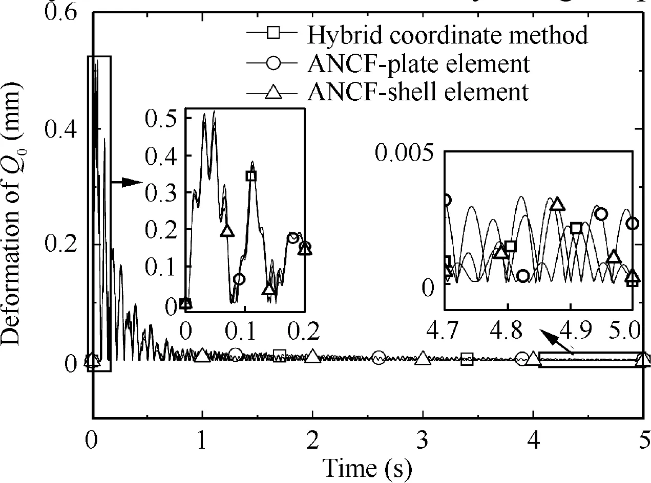
Fig. 10 Deformation of Q0 analyzed by three methods in deployment process.
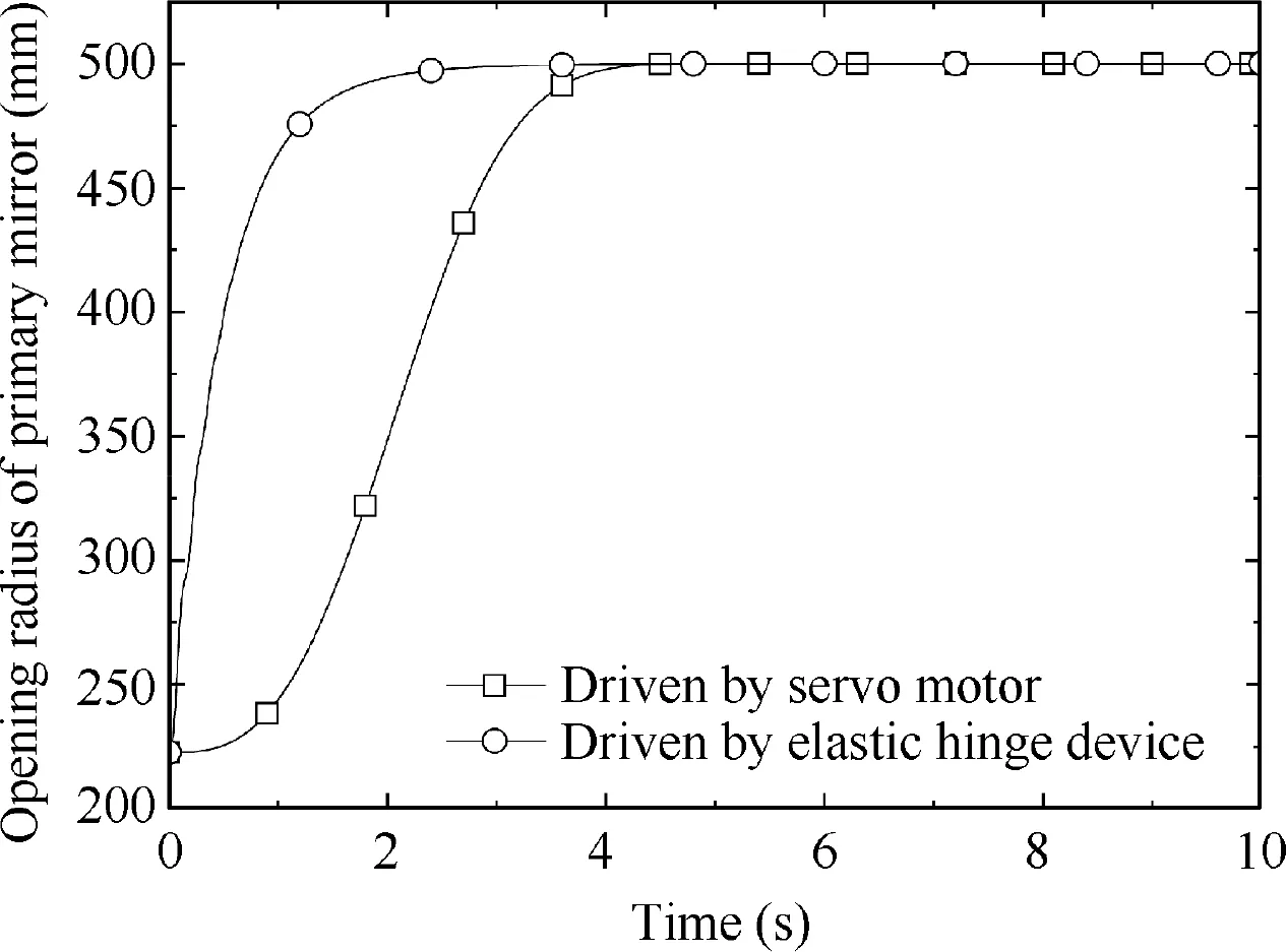
Fig. 11 Opening radius variation rule of primary mirror in two driving conditions.
Angular velocity and angular acceleration during submirrors deploying motion are shown in Fig. 12 and Fig. 13,respectively. When driven by elastic hinge device, the peak of deployment angular velocity of the sub-mirror sharply reaches 180.0(°)/s at initial time,and will reduce to zero after 4.0 s.Due to the uncontrollability and vibration of the elastic hinge device, periodically oscillation will occur during deployment process. However, the deployment angular velocity of the sub-mirror driven by servo motor presents a regular sinusoidal motion law. During 0-5.0 s, the angular velocity accelerates slowly and reduces to zero without high frequency oscillation.According to Eq. (56), when the elastic stiffness K and damping torque Tof spring hinge are constant,the deploying speed of the sub-mirror decreases with time.Also,it can be seen that the frequency variation of deployment angular acceleration of the mirror driven by the elastic hinge device is much larger than that by the servo motor.It is not conducive for maintaining the surface accuracy of mirror. Extremely, acceleration oscillations will damage the structural characteristics of mirrors,even cause the resonance of some components in the telescope system.Therefore,the elastic hinge device is not suitable for deployment motion of the sub-mirrors.
The rigid-flexible coupling effect will inevitably occur in the deployment process. The vibration caused by the coupling of deployment motion and flexible deformation of the surrounding sub-mirrors will be transmitted to the center sub-mirror,it will induce the deformation of the mirrors.Fig.14 and Fig.15 show the deformations of point (Q) and hinge joint (JQ) of sub-mirror in the vertical direction under different driving conditions, respectively. It can be seen from the figure, the maximum deformation of Qcan reach ±0.05 mm driven by elastic hinge, which is much higher than that driven by servo motor. The deformation mainly occurs in the initial motion,and it also causes greater impact. With the angular velocity of the sub-mirror increasing, the virtual work δWof the primary mirror system will become larger and the virtual strain energy δW will maintain constant. These cause the displacement vector rof the sub-mirror much larger. Under the action of the flexible deformation of the surrounding submirrors and different driving conditions, the deformation of center sub-mirror also becomes large.The maximum deformation of JQreached ±0.4 mm driven by elastic hinge device,and it is ±0.001 mm driven by servo motor. The center submirror is connected with multiple surrounding sub-mirrors,its deformation characteristics will be more complex when multiple sub-mirrors simultaneously deploying. Therefore, it is necessary to study the dynamic behavior of the flexible deployable primary mirror system.
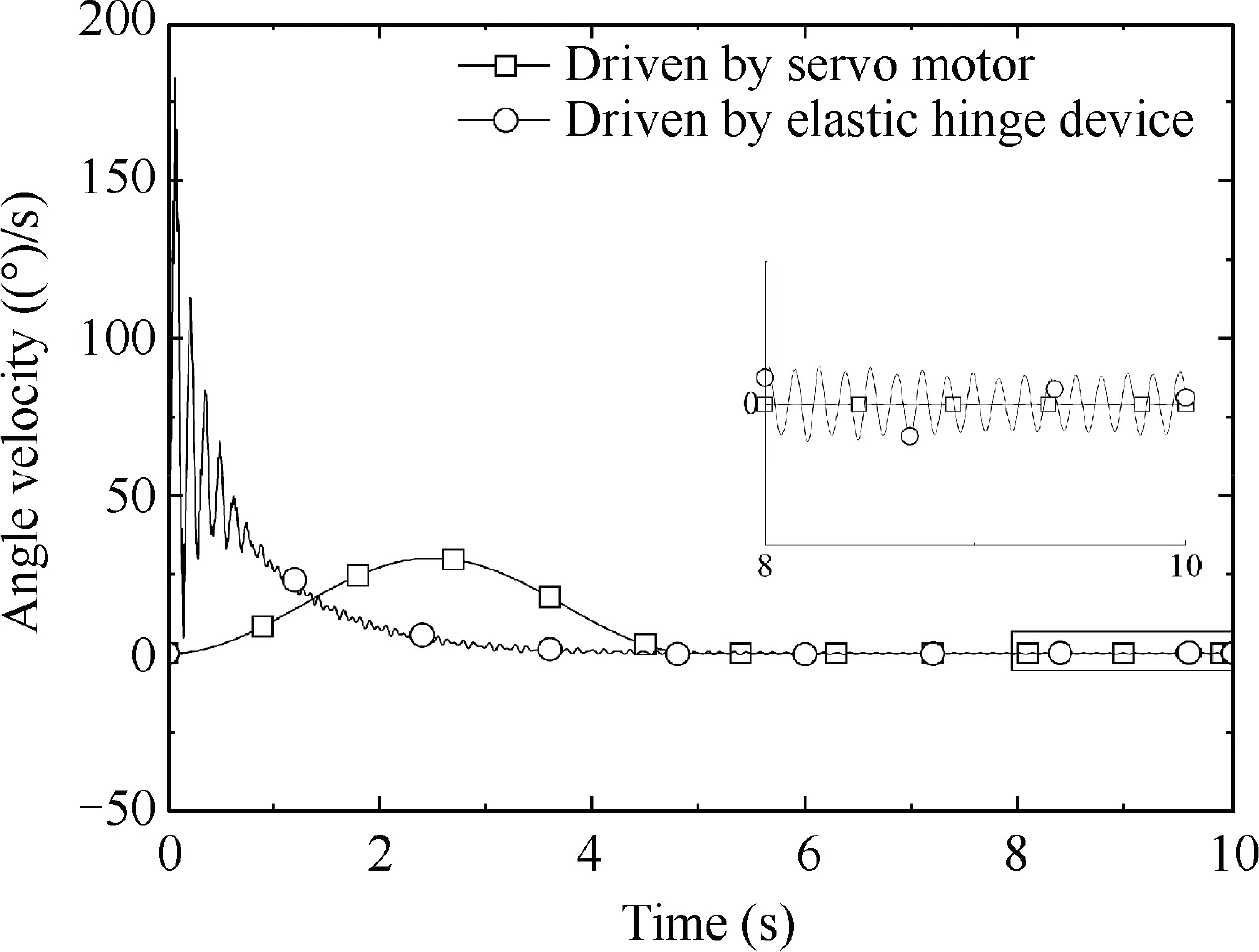
Fig. 12 Angular velocity of sub-mirrors during deployment process with two driving conditions.
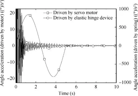
Fig. 13 Angular acceleration of sub-mirrors during deployment process with two driving conditions.
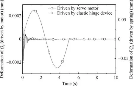
Fig. 14 Deformation of Q0 in z direction with two driving conditions.
4.2. Deployment analysis of sub-mirrors with different deployment strategies
Space telescope can be regarded as rootless multi-body system floating in space. The torque generated during deployment process will impact satellite body and interfere with the attitude of the satellite body and pointing accuracy of the primary mirror. Different deployment strategies have different effects of pointing accuracy.
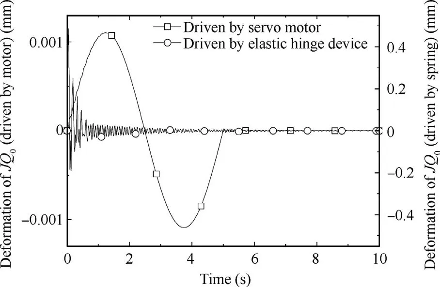
Fig. 15 Deformation of JQ0 in z direction with two driving conditions.
In order to investigate the influence of different deployment strategies, numerical simulations are carried out for one, two,and four forward deployable sub-mirrors with simultaneous deployment in Fig.16.Because of the same shape and symmetrical layout of sub-mirrors driven by servo motor according to Eq. (57), the dynamic response of backward deployable submirrors in the deployment process are similar to forward deployable sub-mirrors.

Fig. 16 Deployment motion of sub-mirrors with different numbers.
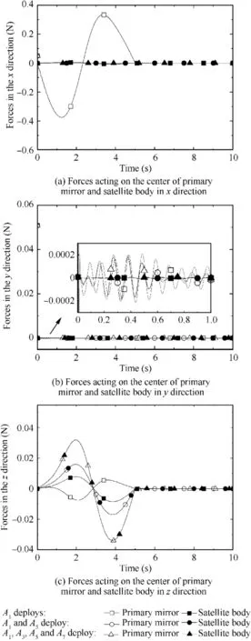
Fig. 17 Forces acting on the center of primary mirror and satellite body.
Fig.21 and Fig.22 show pointing angular deviation and zdisplacement at the center of the primary mirror and satellite body using different deployment strategies.It can be seen that deviation is much greater for single sub-mirror Adeployment than that for symmetrical layout of sub-mirrors deployment.However, it can be deduced that the displacement of the primary mirror and satellite body in the z direction will increase with the increase of the number of deployment sub-mirrors.
Fig.23 shows the z-displacement of hinge joints using three different strategies. In the deployment process, the drastic change of generalized force matrix Qleads to the increase of virtual work of inertia force Wand the oscillation of hinge joint vector ron the primary mirror, so the hinge joints with higher impact energy will affect the other hinges. Vibration attenuates with time in a sinusoidal form, and it approaches to a steady state finally.Hence,it can be deduced that symmetrical layout of sub-mirrors deployment will provide a more reasonable mode to deploy simultaneously by servo motor,and it will have less effect on satellite attitude and telescope pointing.
5. Conclusions
Firstly, the elastic deformation of flexible mirrors is described by the ANCF-shell element in this paper. The flexible mirrors are discretized into equal thickness shell element. Then, the stress-strain expressions of mirrors with nonlinear constitutive relation are obtained by considering characteristics of the laminated material and paraboloidal structure. Compared with traditional plate element, the present model is suitable for the accuracy of large deformation solution of flexible laminated mirrors.
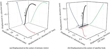
Fig. 18 Displacement of primary mirror center and satellite body center in deployment process of single sub-mirror (A1.)
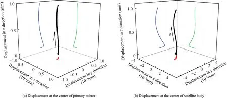
Fig.19 Displacement of primary mirror center and satellite body center in simultaneous deployment process of two sub-mirrors(A1 and A5).
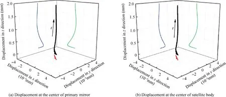
Fig.20 Displacement of primary mirror center and satellite body center in simultaneous deployment process of four sub-mirrors(A1,A3 A5 and A7).
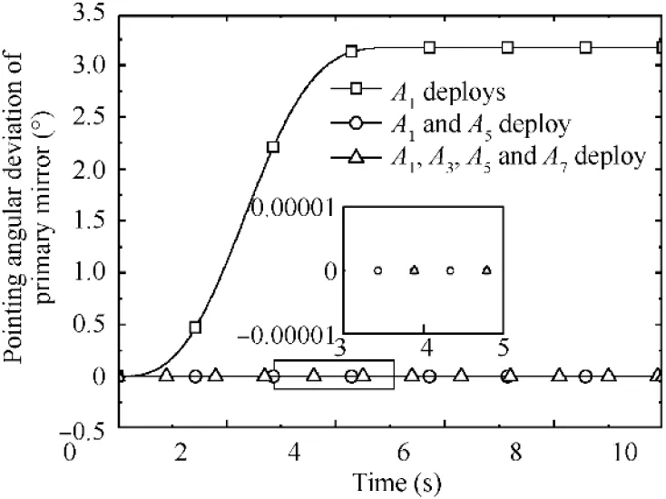
Fig.21 Pointing angular deviation of primary mirror with three deployment strategies.
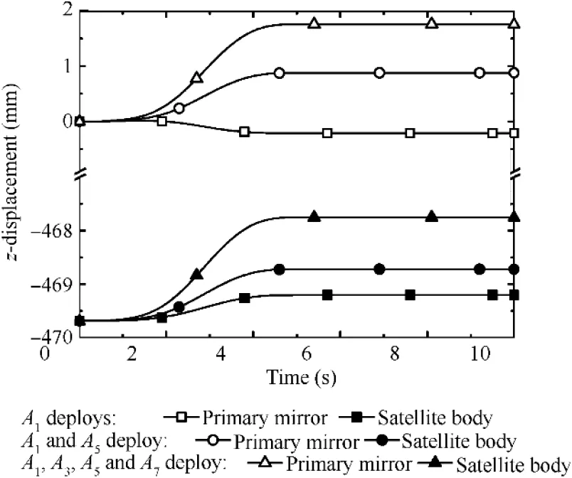
Fig. 22 z-displacement at the center of primary mirror and satellite body with three deployment strategies.
Secondly,the primary mirror of the telescope is regarded as a clustered multi-body system according to the layout characteristics of flower-like deployable sub-mirrors. The nonlinear dynamic equations of mirrors during deployment process are established by virtual work principle. And, the equations can accurately describe mass matrix, stiffness matrix, and external force matrix of the system. So it can simplify the computational complexity. Furthermore, coupled dynamic behavior of flexible deformation and deployment motion of mirrors is studied.
Finally,simulation results explain that oscillation of flexible mirrors will affect the surface accuracy of primary mirror during deployment process. Compared with that driven by servo motor, the impact force is larger than that driven by elastic hinge device, and it is not suitable for the stability of mirrors deployment motion.Furthermore,the pointing angular deviation of the primary mirror can be reduced by symmetrical layout of sub-mirrors with simultaneous deployment, and the simulation results of a flexible sub-mirror with laminate material and paraboloidal structure are used to verify the criterion.It is concluded that it will have less effect on satellite attitude and telescope pointing.
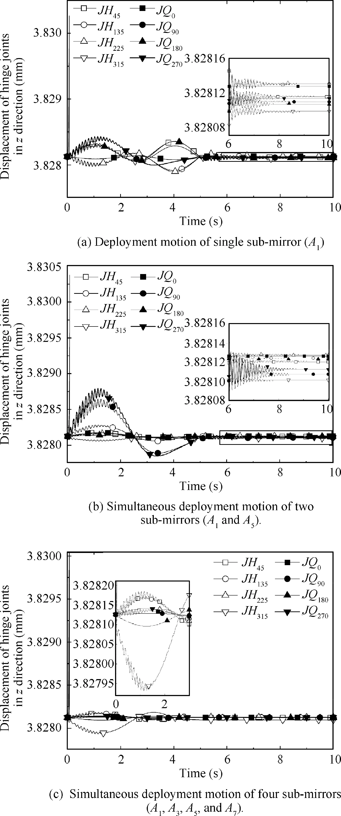
Fig.23 Displacement of hinge joints in the z direction with three deployment strategies.
Declaration of Competing Interest
The authors declare that they have no known competing financial interests or personal relationships that could have appeared to influence the work reported in this paper.
Acknowledgement
sThe authors are particularly grateful for Professor Zhao Yang of Harbin Institute of Technology. This material is based on Project 51575126 supported by the National Natural Science Foundation of China, and Projects 2013M541358 and 2015T80358 supported by the China Postdoctoral Science Foundation.
 CHINESE JOURNAL OF AERONAUTICS2021年4期
- CHINESE JOURNAL OF AERONAUTICS的其它文章
- Time delay compensation in lateral-directional flight control systems at high angles of attack
- Dual stability enhancement mechanisms of axial-slot casing treatment in a high-speed mixed-flow compressor with various tip clearances
- Development cost prediction of general aviation aircraft using combined estimation technique
- Improvement on shaped-hole film cooling effectiveness by integrating upstream sand-dune-shaped ramps
- Modeling and parameter identification of linear time-varying systems based on adaptive chirplet transform under random excitation
- An experimental method to obtain the hard alpha anomaly distribution for titanium alloy aeroengine disks
