Cutting path-dependent machinability of SiCp/Al composite under multi-step ultra-precision diamond cutting
Shijin LU, Junjie ZHANG,*, Zengqing LI, Jinguo ZHANG,Xiohui WANG, Alexnder HARTMAIER,d, Jinfeng XU, Yongd YAN,To SUN
a Center for Precision Engineering, Harbin Institute of Technology, Harbin 150001, China
b State Key Laboratory of Digital Manufacturing Equipment and Technology, School of Mechanical Science and Engineering, Huazhong University of Science and Technology, Wuhan 430074, China
c School of Mechanical Engineering, University of Jinan, Jinan 250022, China
d Interdisciplinary Centre for Advanced Materials Simulation, Ruhr-University Bochum, Bochum 44780, Germany
KEYWORDS Cutting path;Diamond cutting;Finite element simulation;Particle-tool interaction;SiCp/Al composites
Abstract Particle-tool interactions, which govern the synergetic deformation of SiC particle reinforced Al matrix composites under mechanical machining,strongly depend on the geometry of particle position residing on cutting path. In the present work, we investigate the influence of cutting path on the machinability of a SiCp/Al composite in multi-step ultra-precision diamond cutting by combining finite element simulations with experimental observations and characterization. Be consistent with experimentally characterized microstructures, the simulated SiCp/Al composite is considered to be composed of randomly distributed polygonally-shaped SiC particles with a volume fraction of 25vol%. A multi-step cutting strategy with depths of cut ranging from 2 to 10 μm is adopted to achieve an ultimate depth of cut of 10 μm. Intrinsic material parameters and extrinsic cutting conditions utilized in finite element simulations of SiCp/Al cutting are consistent with those used in corresponding experiments.Simulation results reveal different particle-tool interactions and failure modes of SiC particles,as well as their correlations with machining force evolution,residual stress distribution and machined surface topography. A detailed comparison between numerical simulation results and experimental data of multi-step diamond cutting of SiCp/Al composite reveals a substantial impact of the number of cutting steps on particle-tool interactions and machined surface quality. These findings provide guidelines for achieving high surface finish of SiCp/Al composites by ultra-precision diamond cutting.
1. Introduction
Silicon carbide(SiC)particle reinforced aluminum(Al)matrix composites (SiCp/Al) as important engineering materials have been widely used in aerospace,automotive industry,electronic engineering and biotechnology, due to their superior physical and mechanical properties such as low density, high specific stiffness,high fatigue,wear and corrosion resistance,low thermal expansion and low cost.Along with the increasing requirement on the performance of SiCp/Al-based components and devices, high machined surface finish such as low surface roughness and high surface integrity is greatly needed.In addition to efficient but moderate accurate grindingand highly accurate but time-consuming polishing,mechanical cutting has also been proposed to machine SiCp/Al composites to achieve high surface quality.However, the introduction of brittle SiC particles greatly lowers ductility and fracture toughness of pure Al matrix, which subsequently leads to a decrease in the machinability of the composites.
The low machinability of SiCp/Al composites is dominated by the poor synergetic deformation behavior between Al matrix and SiC particles, given their significantly different physical and mechanical properties. Ge et al.indicated that the cutting-induced plastic deformation and fracture of SiCp/Al composites can be accommodated by different deformation modes. Schubert and Nestlerpointed out that the complex deformation behavior of SiCp/Al under cutting can be contributed by the elastic-plastic deformation and ductile damage of the metallic matrix, the elastic deformation and brittle failure of the ceramic particles,as well as the debonding of matrixparticle interfaces. Furthermore, there are strong interactions between individual deformation modes,such as strain hardening of metallic matrix caused by particle hindering dislocation motion. Therefore, the modulation of particle-tool interaction is critical to facilitate the synergetic deformation between SiC reinforcement and Al matrix, which in turn enhances the machinability of SiCp/Al composites.
In addition to intrinsic material parameters such as the size and volume fraction of SiC particles, Dabade et al. revealed that extrinsic machining parameters also have a strong impact on the machinability of SiCp/Al composites.In particular,depth of cut (DOC) is a key parameter that determines the interaction between tool and particles, in particular when it is comparable to particle sizes. While the size of SiC particles is usually a few microns, the DOCs utilized in most previous theoretical and experimental studies of SiCp/Al composites cutting have the order of at least tens of microns, which falls into the regime of precision machining. On the other side,ultra-precision machining using small DOCs down to a few micrometers even sub-micrometers have been widely used to achieve ultra-smooth surface for a variety of materials.In particular, there is limited work on SiCp/Al composites cutting using small DOCs reported.Kannan and Kishawy successfully applied ultra-precision cutting using small DOC to achieve ultra-smooth machined surface for SiCp/Al composite.Cheung et al. achieved better surface finish of SiCp/Al composite with diamond turning.Ge et al. indicated that smaller DOC results in better machined surface quality and surface finish in ultra-precision machining of SiCp/Al composites.
In particular, the strategy of utilizing multi-step cutting with a small DOC of just a few microns is usually adopted in ultra-precision diamond cutting.Dehmani et al.developed a multi-step cutting model of orthogonal cutting, with which they studied the influence of the cumulated strain and temperature induced by different cutting steps on the residual stresses.Shao et al.proposed an analytical algorithm to predict the final residual stresses induced by a strategy of multi-step cutting. Hou et al.indicated that surface roughness can be greatly affected by work hardening and thermal softening occurred in previous cutting steps during multi-step orthogonal cutting. Therefore, in the multi-step cutting process of SiCp/Al composites, the residual stress generated in previous cutting steps may have a strong impact on subsequent material removal,as the significant stress relaxation and elastic recovery alter tool-particle interactions. However, to the best of our knowledge, no published work has yet addressed the multistep diamond cutting of SiCp/Al composites. Thus, a fundamental understanding of the DOC-dependent particle-tool interactions and their correlations with machining parameters is greatly needed to facilitate the machinability of SiCp/Al composites by multi-step diamond cutting.
Finite element (FE) techniques have been demonstrated to be a powerful tool for elucidating deformation mechanisms of various materials.In particular for the cutting of particle reinforced composites, Pramanik et al. performed FE simulations to investigate the development of stress and strain fields,as well as tool wear, particle debonding and uneven deformation of matrix materials during orthogonal cutting of SiCp/Al composites.Wang et al.conducted FE simulations of SiCp/Al composites cutting to reveal different types of fracture behavior of SiC particles. Moreover, Zhou et al.established FE models of orthogonal cutting of SiCp/Al composites to investigate the influence of cutting parameters on machinability of the composites, in terms of edge defect size,machined surface profile and subsurface residual stress distribution. Liu et al.performed FE simulations to investigate the effect of grinding parameters on surface defects generated in high-speed grinding of particulate reinforced titanium matrix composites. Sandhiya et al.carried out FE simulations to investigate the influence of volume fraction, size,shapes and distribution of SiC particles on particle-tool interactions, chip formation and residual stress pattern during SiCp/Al composites cutting. Du et al.performed FE studies of single diamond grain cutting of SiCp/Al composites to analyze the removal of SiC particles from Al matrix, as well as its correlation with surface formation mechanisms.
Although previous FE simulations have provided valuable insights into the cutting process of SiCp/Al composites, our fundamental understanding of the mechanisms involved during the multi-step ultra-precision diamond cutting of SiCp/Al composites is far from complete. Specifically, many assumptions were made on the modeling of SiC particles in previous FE simulations of SiCp/Al machining, such as linear elastomers, spherical shape and uniform size and distribution,etc. Such simplified assumptions are inconsistent with the real microstructural characteristics of the composites observed experimentally. Fracture of SiC particles is an important failure mode that determines the stress concentration introduced by SiC particles. For instance, the stress concentration in the vicinity of SiC particles with arbitrary polygonal shapes and irregular distributions will be significantly different from that associated with spherical particles. Consequently, there are large uncertainties when directly comparing the simplification-associated numerical simulation results with cutting experiments. Therefore, incorporating the real morphology of the SiC particles into the FE models of SiCp/Al machining is essentially required for promoting the prediction accuracy by FE simulations.
2. Materials and methods
2.1. Characterization of SiCp/Al composite
The specimen is an extruded bar of SiCp/Al composite with a diameter of 20 mm and a thickness of 5 mm. The matrix is an Al6063 alloy. The SiC particles have a volume fraction of 25vol%, with an average particle size of 10 μm. In order to clear observe the geometry of SiCp/Al composites and verify FE simulation results,there is a high requirement on the specimen condition such as surface roughness in the cutting experiments. Thus, prior to diamond cutting, the specimen is subjected to annular polishing to achieve a surface roughness of 63 nm. Fig. 1 shows a scanning electron microscope(SEM)image of the surface of as-polished SiCp/Al composites,which demonstrates the geometrical characteristics of the SiC particles such as arbitrary polygonal shapes, random sizes and irregular distribution.
2.2. Experimental setup of orthogonal cutting of SiCp/Al composites
The orthogonal diamond cutting of the SiCp/Al composite is performed in a Precitech Nanoform X ultra-precision lathe.Fig. 2 shows the experimental configuration of diamond cutting. The specimen is statically mounted in the vacuum chuck of air spindle.In the multi-step cutting process,three DOCs of 2, 5 and 10 μm are utilized in order to achieve an ultimate DOC of 10 μm. Therefore, the number of cutting steps used is 5, 2 and 1 for the DOC of 2, 5 and 10 μm, respectively.The same cutting speed of 5 mm/s is used for each cutting step.A natural single crystalline diamond tool with a rake angle of-20°, a clearance angle of 20° and a cutting edge radius of 60 nm is used. After diamond cutting, machined surface is characterized by SEM and a white light interferometer.
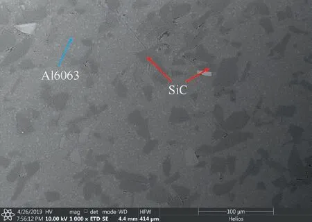
Fig. 1 SEM image of as-polished SiCp/Al composite.
2.3. FE modeling of orthogonal cutting of SiCp/Al composite
Fig. 3(a) shows the 2D FE model of orthogonal cutting of SiCp/Al composites, which is composed of a specimen of SiCp/Al composite material and a diamond tool. Due to the limitation of computational capacity, a small size of the specimen with 120 μm in length and 50 μm in height is selected in the FE model.The specimen is extracted from a large SiCp/Al sample with size of 250 μm by 250 μm, as shown in Fig. 3(b).To be consistent with the real microstructure of SiCp/Al composite shown in Fig. 1, the large sample consists of randomly distributed polygonally-shaped SiC particles with a volume fraction of 25vol%. Furthermore, the equivalent mean size of SiC particles follows a Gaussian distribution with a mean value of 10 μm and standard deviation of 1. The specimen has been discretized using 4 node brick elements and a regular mesh size of 0.5 μm.The bottom layer of the specimen is fully constrained, and the other layers are free of any constraint.The interface nodes of matrix and particles are tied together.Thus, the debonding of SiC particle-Al matrix interfaces can be achieved by the failure of Al matrix around SiC particles.The simulated diamond tool as a rigid body has the same geometry with that used in experiments. To mimic the configuration of orthogonal cutting experiments, in the FE simulations the diamond tool cuts the specimen surface with a predetermined DOC and a constant cutting speed of 5 mm/s. In addition, the multi-step cutting strategy and related DOCs adopted in the FE simulations are the same with that used in the experiments.
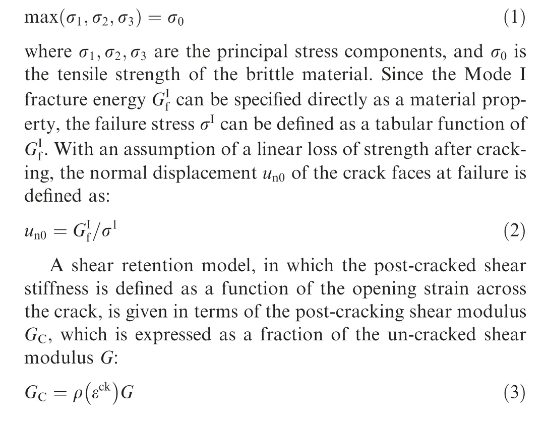
Table 1 lists the physical properties of Al6063 matrix and SiC particles used in the FE simulations. The Johnson-Cook(J-C)model is adopted to describe the elastic-plastic deformation of Al matrix.A local ductile J-C damage criterion based on a critical equivalent plastic strain is adopted to achieve material separation and chip formation.The detailed parameters used in the J-C constitutive model for Al6063 alloy are the same with that used by Mabrouki et al.The SiC particles are assumed to behave elastically and plastically.The brittle failure of SiC particles is described by a normal stress criterion defined as:
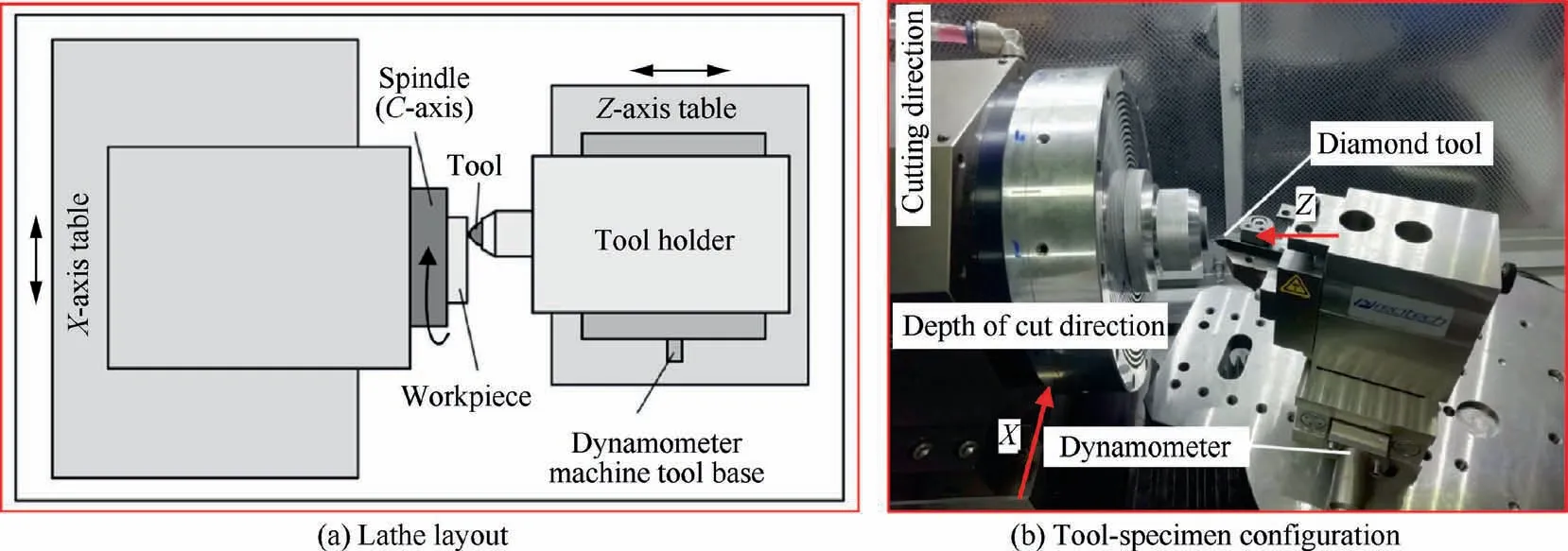
Fig. 2 Experimental configuration of orthogonal diamond cutting.

Fig. 3 FE model of orthogonal cutting of SiCp/Al composites.
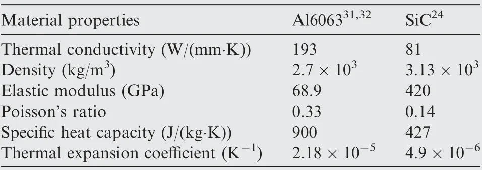
Table 1 Physical parameters of Al6063 and SiC.

3. Results and discussion
3.1. Cutting mechanisms of SiCp/Al composite
FE simulation of orthogonal cutting with a DOC of 10 μm,i.e., a single cutting step, is firstly performed to reveal the involved cutting mechanisms of SiCp/Al composites. Fig. 4(a)shows the movement path of cutting tool edge within a cutting distance of 120 μm,which indicates the interaction of tool edge with 6 different SiC particles.Three different types of relative positions of cutting tool edge with respect to the center of mass (COM) of each particle can be identified. Specifically,Particles 1 and 5 are above the cutting path,Particle 3 is below the cutting path, and Particles 2, 4 and 6 are traversed by the cutting path.
Fig. 4(b) shows variations of cutting force and thrust force during the cutting process of SiCp/Al composite with a DOC of 10 μm.Moreover,the contacting of a SiC particle with tool edge is highlighted by an elliptical circle. It can be seen from Fig.4(b)that both cutting force and thrust force for Al matrixare significantly smaller than that required to cut through SiC particles. Furthermore, cutting force is significantly higher than thrust force,irrespective of whether it involves the cutting of Al matrix or SiC particles. For the cutting of each SiC particle, cutting force increases rapidly when cutting tool edge approaches SiC particles, and reaches a maximum value when the cutting is performed on SiC particles, followed by a sharp drop when cutting tool edge moves across SiC particles.

Table 2 Parameters of brittle cracking model for SiC particles.24
Fig. 4(b) also suggests that the relative position between cutting tool edge and SiC particles has a strong influence on the evolution of cutting force. For Particles 1 and 5 with COMs below cutting tool edge: while the particle-tool edge contact occurs in the lower middle part of Particle 1, the local maximum value of cutting force is greater than that for the other SiC particles. The particle-tool edge contact occurs at the bottom of Particle 5, for which the cutting force is smaller but has more pronounced fluctuations than those of Particle 1.While the particle-tool edge contact occurs in the middle part of Particles 2, 4 and 6, where the COMs approximately coincide with cutting tool edge,corresponding variations of cutting force have similar characteristics.However,the fluctuations of cutting force for Particle 6 is more pronounced than those for Particles 2 and 4.Particle-tool edge contact occurs in the upper middle part of Particle 3 with COMs above cutting tool edge,for which the cutting force exhibits only one wave peak, and has less pronounced fluctuations than those of the other particles.Interestingly,Fig.4(b)reveals a significant increase in the cutting force when cutting tool cuts through the Al matrix between Particles 5 and 6. The subfigure in Fig. 4(b) presents a magnified view of the surface between Particles 5 and 6 after cutting, which demonstrates a small top fracture behavior of the particles under the cutting path. Consequently, due to the fracture particle at the bottom of Al matrix,the uncut layer on the left of the broken particle remains in the specimen,and the resulted work hardening of surrounding Al matrix leads to the obvious increase in cutting force for cutting between Particles 5 and 6.
27. A beautiful son: A first born son would be the crown prince. Giving up the crown prince to the manikin would not be just a personal tragedy for the Queen, but a possible disaster for her kingdom which relies on progeny to avoid strife in the royal lineage.Return to place in story.
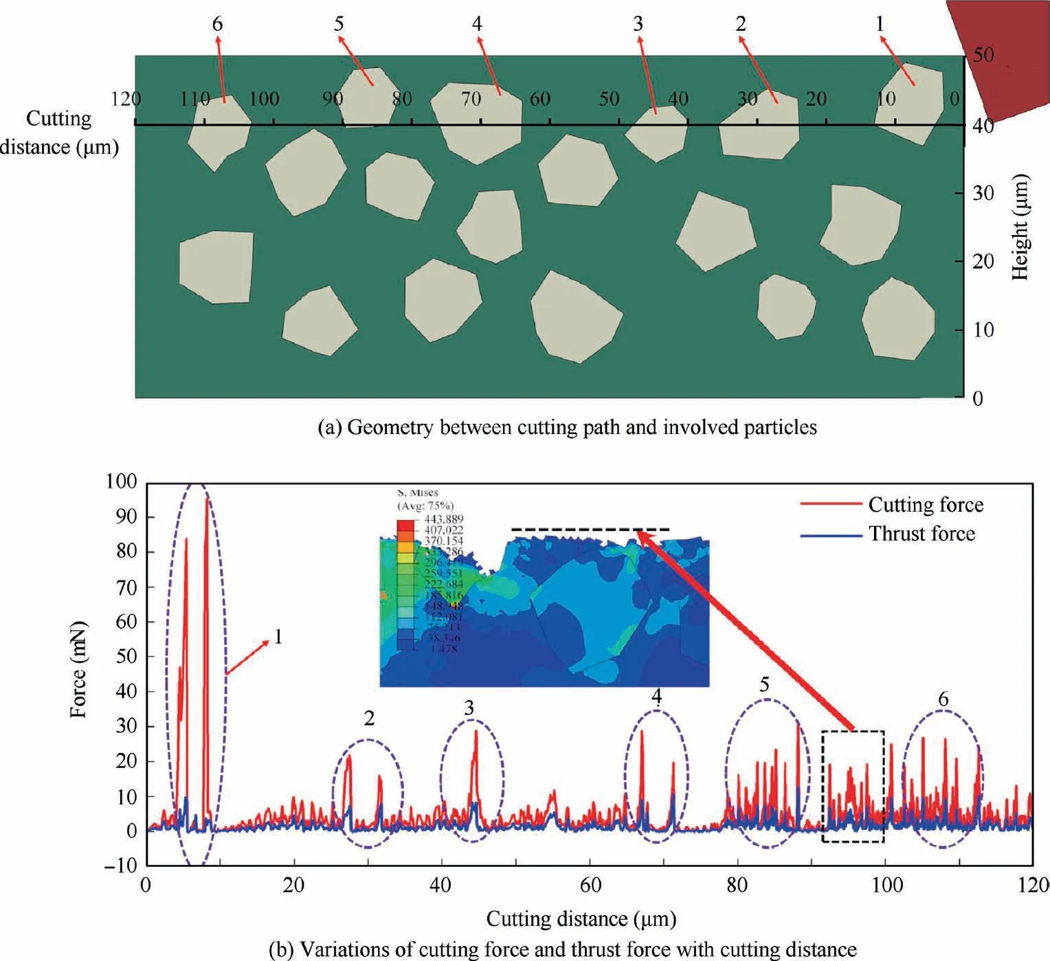
Fig. 4 FE simulation results of orthogonal cutting of SiCp/Al composite with a DOC of 10 μm.
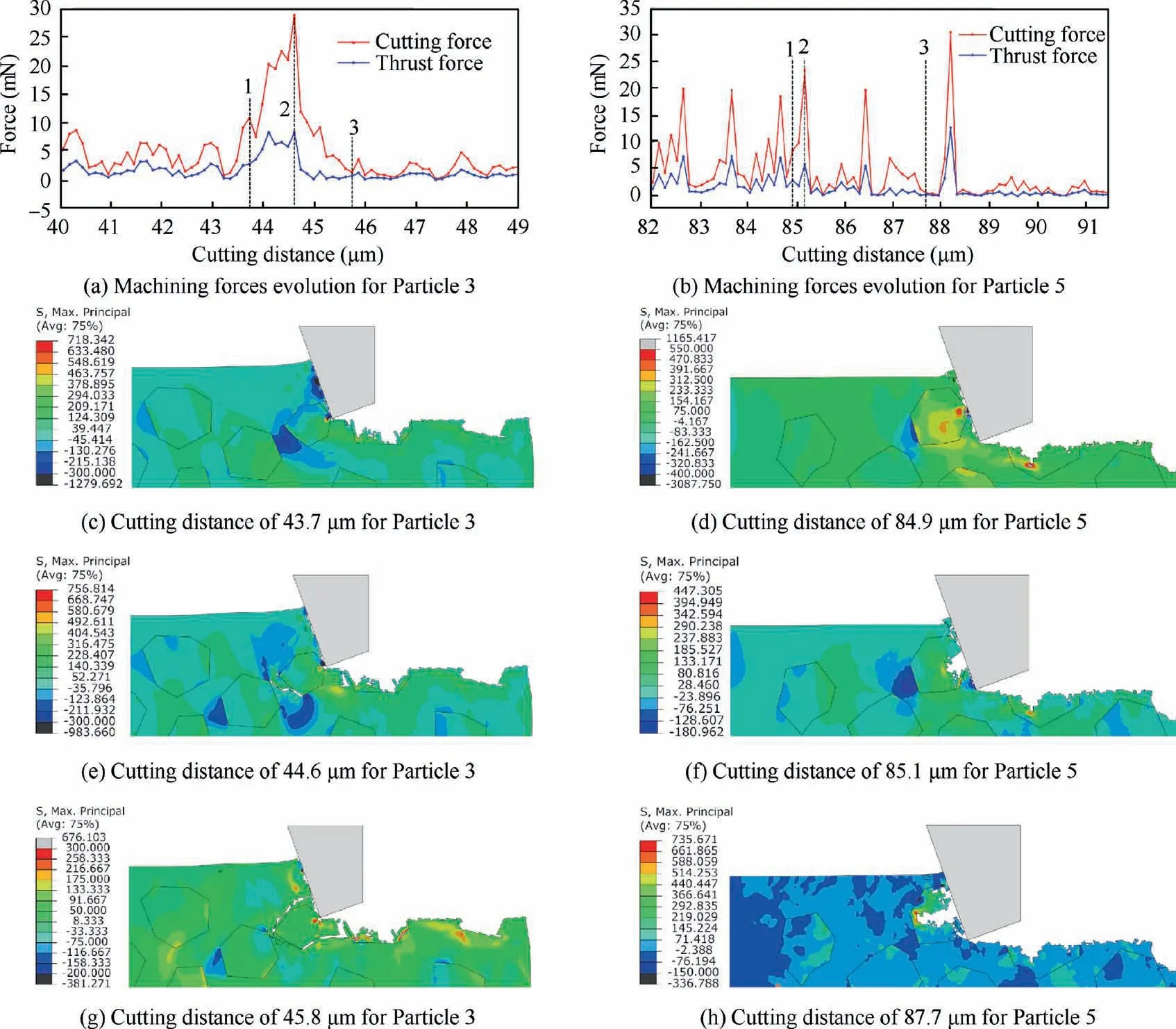
Fig. 5 FE simulation results of particle-tool interactions in orthogonal cutting of SiCp/Al composites with a DOC of 10 μm.
Fig.5(a)and(b)show additional variations of cutting force and thrust force when cutting is performed in the vicinity of Particles 3 and 5 with a DOC of 10 μm, respectively. Accordingly,Fig.5(c)-(h)present cutting configurations of Particles 3 and 5 at different cutting distances indicated by the numbers shown in Fig.5(a)and(b).It is seen from Fig.5 that the deformation in the vicinity of Particle 3 is significantly different from that in Particle 5. With the advancement of cutting tool edge, the tearing of Al matrix around Particle 3 leads to debonding of matrix-particle interfaces.Consequently,Particle 3 is completely removed from the matrix without brittle fracture, leaving a cavity on machined surface. The cutting force reaches its local maximum when complete dislodging of Particle 3 occurs. In contrast, Particle 5 undergoes a clear brittle fracture. There are successive events of crack nucleation and propagation occurring within Particle 5, which are accompanied by rapid fluctuations of cutting force. Furthermore, the cutting force reaches its local maximum value before the fracture of Particle 5, followed by chip formation. Fig. 5 suggests that a better surface integrity can be obtained for Particle 5 than that for Particle 3, due to the absence of debondinginduced cavity.
Fig. 6(a) presents configuration of SiCp/Al specimen after cutting with a DOC of 10 μm, which is colored by residual stress contours. To clearly show the cutting-induced surface morphology evolution of the specimen, intact particles before cutting are also presented with red lines. It is intuitively seen from Fig. 6(a) that there are different modes of SiC particletool interactions occurred: (i) Complete particle removal within formed chip composed of Al matrix (Particles 1 and 5), (ii) Fractured particles remaining in Al matrix after being partially broken(Particles 2,4 and 6),and(iii)Particle dislodging from Al matrix through debonding(Particle 3).The different modes of particle-tool interactions observed are closely associated with different positions of cutting tool edge with respect to COMs of SiC particles. In addition, it can be seen from Fig.6(a)that tensile and compressive stresses are present only at matrix-particle interfaces. Furthermore, the distribution of residual stresses in the vicinity of randomly distributed SiC particles is not regular. Fig. 6(b) further shows the profile of machined surface in terms of surface height variations.While the dislodging of SiC particles from Al matrix results into the formation of cavities, the partial fracture of SiC particles leads to improved machined surface finish. The largest cavity,caused by the debonding of Particle 3 from surrounding Al matrix,has a width of 30 μm,which is larger than the average particle size of 7.6 μm.
3.2. Influence of cutting step
To address the influence of cutting step on the multi-step cutting of SiCp/Al by FE simulations, two other DOCs of 2 and 5 μm are also considered,in addition to the DOC of 10 μm.To achieve an ultimate DOC of 10 μm, the number of cutting steps for the DOC of 2 and 5 μm is 5 and 2, respectively.Fig. 7(a)-(c) represents the cutting path for the DOC of 2, 5 and 10 μm, respectively. When each cutting step is completed,the cutting tool is firstly lifted up by 2 μm and then returns back to the starting point to start the next cutting step within a duration of 0.014 s.
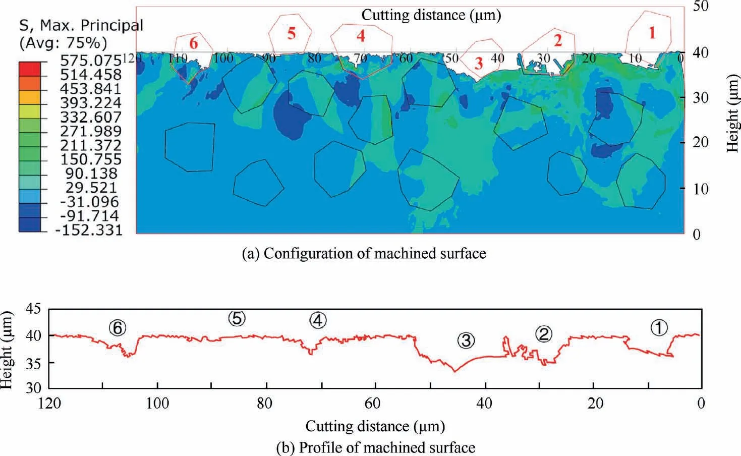
Fig. 6 FE simulation of machined surface morphology after cutting of SiCp/Al composites with a DOC of 10 μm.
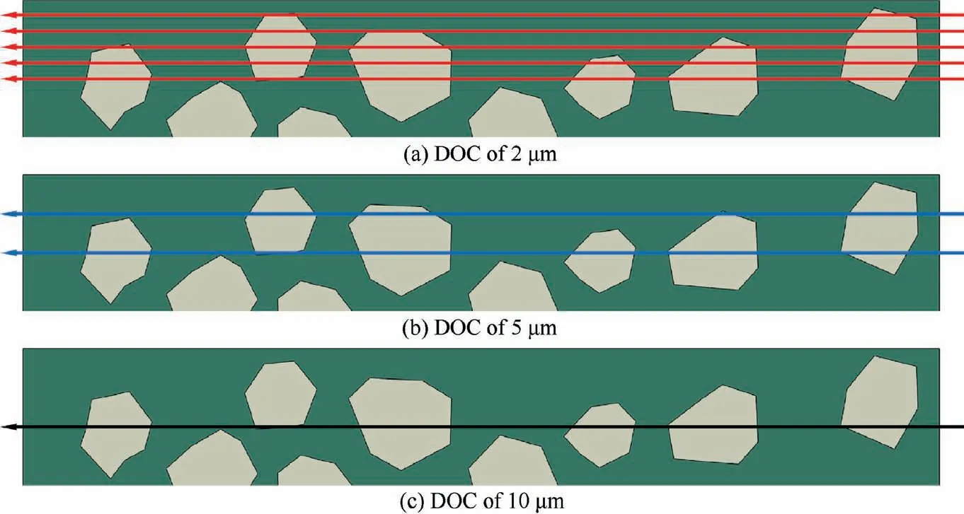
Fig. 7 Schematic illustration of cutting paths in FE simulation of multi-step cutting of SiCp/Al composites with different DOCs.
Fig. 8(a) shows variations of cutting force in the 5 cutting steps with a DOC of 2 μm. These results reveal that the number of cutting force peaks in each cutting step is different from each other due to different tool-particle interactions. Interestingly, there are periods where cutting force is zero in cutting steps 3-5, which is due to the travelling of tool edge across a cavity formed in a previous cutting step. Fig. 8(b) shows variations of average cutting force and thrust force with the number of cutting steps. It is seen from Fig. 8(b) that both cutting force and thrust force first increase in the first two cutting steps, but then decrease in the subsequent cutting steps. However, both cutting force and thrust force increase at the final cutting step.In the first cutting step,the tool edge dominantly contacts Al matrix rather than SiC particle, and there are two cutting force peaks observed when cutting tool edge contacts with Particles 1 and 5. The frequency at which tool edge contacts SiC particles increases with cutting steps,which also leads to an increased number of cutting force peaks. The heterogeneous deformation behavior of both Al matrix and SiC particles in each cutting step accounts for the strong evolutions of machining force shown in Fig. 8(b).

Fig. 8 Variation of machining forces in FE simulations of 5 cutting steps with a DOC of 2 μm.
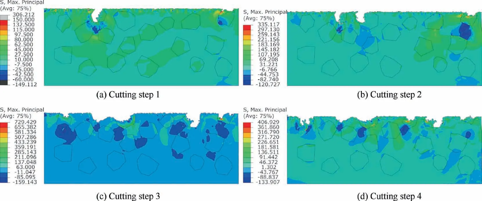
Fig. 9 FE simulation results of machined surface profile with a DOC of 2 μm after different cutting steps.
Fig. 9(a)-(d) present surface topologies of SiCp/Al specimen after cutting using 1, 2, 3 and 4 cutting steps with a DOC of 2 μm. It is seen from Fig. 9 that the residual stresses in the specimen is more pronounced for larger number of cutting steps. While tensile stresses mainly exist in fractured particles and also in the vicinity of fractured particles,compressive stress exists in the matrix between adjacent particles. Due to different numbers and positions of SiC particles lying along the cutting path, the machined surface topology for different cutting steps is significantly different.Fig.9(b)shows that after the first two cutting steps, Particles 4 and 5 are partially broken, which leads to the formation of local cavities. With the increase of cutting steps, the Al matrix in between Particles 4 and 5 is removed, leading to the coalesce of two smaller cavities into a bigger one. The occurrence of particle fracture occurred in the first cutting step lowers the strength of SiC particles containing internal cracks and defects, which subsequently leads to saturation of cutting force increase in following second cutting step.At the same time,it can be seen from Fig. 9(c) that after the completion of the third cutting step, the surface has a large cavity defect, which corresponds to the long period of zero cutting force shown in Fig. 8(a).The presence of zero cutting force further results in a decrease of average cutting force in the fourth cutting step.
Fig.10(a)presents machined surface profiles after different cutting steps with a DOC of 2 μm. It is seen from Fig. 10(a)that the number of cavities formed on machined surface increases with cutting steps, which is closely related with the number of SiC particles involved in cutting path. Fig. 10(a)also suggests that the mechanism by which cavities form is different for different cutting steps.While Cavities 1,3,and 5 are gradually expanded downward when the number of cutting steps increases from 1 to 5, Cavities 2 and 4 with large depths are directly formed due to the removal of SiC particles in previous cutting steps. Fig. 10(b) and (c) show surface roughness after each cutting step with and without considering the presence of cavities, respectively. Fig. 10(b)reveals that when cavities are ignored, the surface roughness increases approximately with cutting steps. However, there exists a critical number of cutting steps for the maximum surface roughness to account for cavities, as shown in Fig. 10(c).
Fig. 11 shows variations of machined surface roughness with DOCs for different cutting strategies at the same final DOC of 10 μm. Two kinds of surface roughness are shown:with and without considering the cavities left behind.It is seen from Fig.11 that the surface roughness without accounting of cavities decreases with decreased number of cutting steps accompanied by increased DOC of single cutting step. However, this trend reverses when the cavities are accounted.
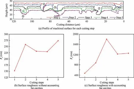
Fig. 10 FE simulation results of machined surface characteristics after 5 cutting steps with a DOC of 2 μm.
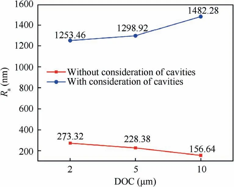
Fig.11 Variations of surface roughness with DOC for the same ultimate DOC of 10 μm.
Fig. 12(a)-(c) present configurations of SiCp/Al specimen after achieving the final DOC with different DOCs in each cutting step, which indicates that the maximum principal stress for the DOC of 2 μm is significantly smaller than that for the other two DOCs. Fig. 12(d) further shows surface profiles for the three cutting processes, which demonstrate that both the depth and width of cutting-induced cavities are strongly affected by the DOC-dependent cutting steps. For Particles 2,4 and 6 with their COMs traversed through by cutting path,the smaller DOC is associated with larger number of cutting steps. This leads to larger number of partially fractured paricles and fewer fully fractured particles remianing in Al matrix,which thus lead to a more pronounced formation of cavities.For Particle 3 with its COM below the cutting path, the coarser DOC leads to larger cavity widths due to the coalence of neighboring cavities. However, it can be seen that the propensity of cavity formation is not influenced by the cutting path for Particles 1 and 5 with their COMs above the cutting path.
3.3. Experimental validation
Multi-step orthogonal cutting experiments of SiCp/Al composite, using the same configuration and cutting parameters as those used in the FE simulations, are also carried out.Fig.13(a)-(d)present SEM images of SiCp/Al composite after the first four cutting steps using a DOC of 2 μm.Fig.13(e)-(h)show corresponding profiles of machined surface for the four cutting steps. In Fig. 13(a), broken of SiC particles are observed after the first cutting step, even though dislodging of SiC particles is rather limited. With the increase of cutting steps, dislodging of SiC particles becomes increased pronounced, in spite of the same DOC of 2 μm. It is seen from Fig. 13(b) that after the second cutting step, the depth of formed surface cavities increases, but their width decreases.Fig. 13(c) reveals that large cavities are formed on the surface after the third cutting step due to dislodging of SiC particles.Furthermore, there is ploughing phenomenon observed on machined surface, which can be attributed to the scratching of the surface by dislodged SiC particles. However, after the fourth cutting step, the machined surface quality is improved due to a decrease in the number and size of cavities. This experimentally-observed trend of machined surface morphology is qualitatively consistent with predicted variations of surface roughness presented in Fig. 10(c).

Fig. 12 FE simulation results of machined surface profile of SiCp/Al composite with different DOCs.
Fig. 14 shows machined surface morphologies of SiCp/Al composite after reaching the same final DOC of 10 μm in multi-step orthogonal cuttings with different DOCs. It is seen from Fig.14 that for each DOC,SiC particles have three types of failure behavior:(i)Fractured particles remaining in Al matrix after partial broken(Position 1),(ii)Complete dislodging from Al matrix through debonding (Position 2), and (iii) Particles being pressed into Al matrix (Position 3). The experimentallyobserved deformation modes of SiC particles are qualitatively consistent with FE simulation results. It is also seen from Fig.14 that the number of cutting steps has a strong influence on machined surface characteristics. In particular, the average cavitysize increases with DOC,for the samefinal DOCof10 μm.
4. Conclusions
FE simulations and corresponding experimental validations are conducted to investigate the machinability of SiCp/Al composites under multi-step orthogonal cutting using a diamond tool. The elastic-plastic deformation of Al6063 matrix is described by the J-C model,and a local ductile J-C damage criterion is used to describe material separation. The elastic deformation and brittle failure of SiC particles are described by a brittle cracking criterion. FE simulation results reveal a strong impact of particle-tool interactions on machined surface topography. It is found that a complete removal of SiC particles within formed chip composed just of Al matrix leads to a smooth surface. Furthermore, when fractured SiC particles remain in Al matrix, the quality of machined surface increases, even though dislodging of SiC particles from Al matrix greatly deteriorates surface quality due to cavity formation. Furthermore, the impact of particle-tool interactions on machining force variations and residual stress distribution depends greatly on the relative position between tool edge and particles. FE simulations and experiments of multi-step orthogonal cutting demonstrate that material removal with a small DOC accompanied with a large number of cutting steps is favorable for improving machined surface quality of SiCp/Al composites by ultra-precision diamond cutting.
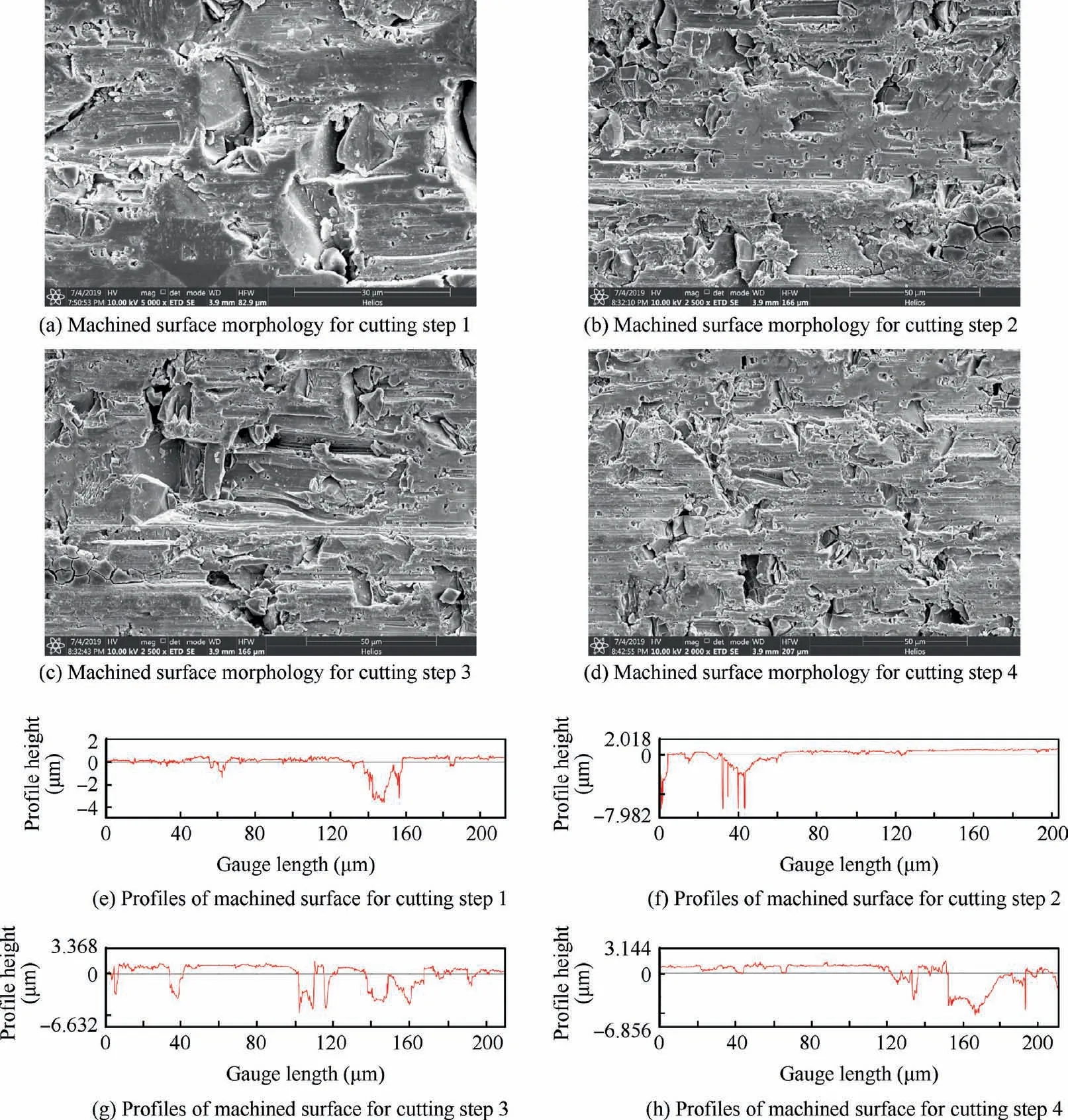
Fig. 13 Experimental characterization of machined surface morphology of SiCp/Al composite after orthogonal multi-step diamond cutting with a DOC of 2 μm for different cutting steps.

Fig. 14 Machined surface morphology of SiCp/Al composites in multi-step orthogonal cutting with different DOCs.
Declaration of Competing Interest
The authors declare that they have no known competing financial interests or personal relationships that could have appeared to influence the work reported in this paper.
Acknowledgement
sThe authors greatly acknowledge supports from the National Natural Science Foundation of China (NSFC)-German Research Foundation(DFG)International Joint Research Programme(51761135106),the Open Research Foundation of State Key Laboratory of Digital Manufacturing Equipment and TechnologyinHuazhongUniversityofScienceandTechnology,China(DMETKF2019016),the Shandong Key R&D Program(2019GGX104027) and the Fundamental Research Funds for the Central Universities.The authors also greatly acknowledge Esteban P.Busso for fruitful discussion and language editing.
 CHINESE JOURNAL OF AERONAUTICS2021年4期
- CHINESE JOURNAL OF AERONAUTICS的其它文章
- Time delay compensation in lateral-directional flight control systems at high angles of attack
- Dual stability enhancement mechanisms of axial-slot casing treatment in a high-speed mixed-flow compressor with various tip clearances
- Development cost prediction of general aviation aircraft using combined estimation technique
- Improvement on shaped-hole film cooling effectiveness by integrating upstream sand-dune-shaped ramps
- Modeling and parameter identification of linear time-varying systems based on adaptive chirplet transform under random excitation
- An experimental method to obtain the hard alpha anomaly distribution for titanium alloy aeroengine disks
