Solid rocket motor propellant grain burnback simulation based on fast minimum distance function calculation and improved marching tetrahedron method
Pengfei REN, Hongo WANG,*, Guofeng ZHOU, Jini LI, Qing CAI,Jiqun YU, Y YUAN
a China Academy of Launch Vehicle Technology, Beijing 100076, China
b School of Chemistry and Chemical Engineering, Beijing Institute of Technology, Beijing 100081, China
KEYWORDS Burning surface area;Finocyl grain;
Abstract To efficiently compute arbitrary propellant grain evolution of the burning surface with uniform and non-uniform burning rate for solid rocket motor,a unified framework of burning surface regression simulation has been developed based on minimum distance function. In order to speed up the computation of the mini-mum distance between grid nodes of grain and the triangular mesh of burning surface,a fast distance querying method based on the equal size cube voxel structure was employed. An improved marching tetrahedron method based on piecewise linear approximation was carried out on second-order tetrahedral elements, achieved high-efficiency and adequate accuracy of burning surface extraction simultaneously. The cases of star grain, finocyl grain,and non-uniform tube grain were studied to verify the proposed method.The observed result indicates that the grain burnback computation method could realize the accurate simulation on unstructured tetrahedral mesh with a desirable performance on computational time.
1. Introduction
Solid Rocket Motor (SRM) has been widely employed in the propulsion system of rockets and tactical missiles with different ranges because of its simplicity, compactness low-cost and high reliability.The pressure-time and thrust-time represent the performance of SRM,captured great attention during the design phase.However,solid propellant motor firing static tests as a way for discovering the phenomena are always costly,therefore, the simulation as an alternative technique can predict the performance economically.Furthermore, SRM grain geometry design is an essential core of SRM in which the precise burning surface regression computation is a critical point that affects the precision, reliability and usability of the design approach.
For specific simple 2D grain,analytical methods are considered effective for the calculation of burning surface regression,but some limitations exist in the application when the geometries are complex, especially in 3D grain configurations.Unfortunately, 2D grain can rarely meet the requirement of the propulsion system,owing to its limited controllable parameters. Alternatively,3D grain plays a vital role in SRM due to its tenability.Hence,a facile and general method that can handle the burning surface regression in the arbitrary 3D grain is necessary to be developed.
As we know, the performance of SRM is determined not only by the geometry of grain but also by the combustion process.In 0D internal ballistics simulation, the flow condition such as pressure and temperature are assumed uniform in the combustion chamber. Thus, the burning rate along the axial direction is constant, and then the burning surface area can be computed independently from the flow field based on the geometrical law of burning.With respect to 0D internal ballistics, the flow conditions are variational with the space and time in 1D and higher-dimensional internal ballistics models.Therefore, the burning rate is both spatially and temporally dependent. It means that the computational method is also demanded to be available in both cases of uniform and nonuniform burning rate.
Various approaches have been explored to realize the burning surface regression of complex grain with uniform or nonuniform burning case, including Generalized Coordinate(GC) method, Computer-Aided Design (CAD) method,Level Set (LS) method, and Minimum Distance Function (MDF) method. Every previous grain burnback simulation technique possesses its advantages.However,there are still barriers existing.
The GC method,as a prominent method,defines the initial grain void via basic geometrical shapes.Based on this method, a popular simulation software named Solid Performance Program (SPP) was firstly released in 1975, which has been regarded as a standard reference computer program.The user is allowed to combine fully coupled and uncoupled surface regression with the internal ballistics module for highly non-uniform grain burnback.Nevertheless, the complexity during the definition process is ultra-high, especially in 3D grain,and the accuracy of burning surface evolution computation relies seriously on the quality of definition. Besides, SPP can probably cause the oscillations in the burning surface calculation.
Grain burnback simulation has also been implemented by commercial CAD software (AutoCAD, CATIA, SOLIDWORKS,I-DEAS,etc.).It can accurately perform the surface offset at each burnt web increment by modeling the parameterization of grain geometry.In the CAD method, the constraints of the parameters need to be defined properly to avoid unnecessary error, and user interaction is more critical in contrast to other methods.
The LS methodis irreplaceable in the field of tracing general evolving surfaces, and it has been well tested and widely used in burnback simulation.In this method,the interface is embedded as the zero-level set of the Signed Distance Function (SDF), and the evolution of zero-level set,which is obtained by solving initial value Partial Differential Equation (PDE) represents the motion of the interface. In the LS method, the geometry can be processed by an implicit representation. Therefore, it is capable of handling complex topological changes with no limitation on the geometric dimension. Besides, there is also no limitation on burning rate distribution.However,it requires more computational time for solving hyperbolic PDE.
The MDF method, which is developed by Willcox et al.,calculated the minimum distance between grid nodes to the burning surface in 3D space. The burning surface was represented by using STereo-Lithography (STL) file format, and the surface regression was calculated at each burnt distance by initial MDF. The MDF method is easy to implement.Besides, compared to the level set method, no PDE needs to be solved.Nevertheless, the method in Ref.is timeconsuming due to the inefficient MDF generation, and can hardly handle the case of arbitrarily distributed burning rate.
For the purpose of efficiently and accurately calculation for SRM grain burning surface regression, a fast numerical method called Improved Marching Tetrahedron Burning Surface Regression (IMTBSR) is developed. Inspired by the fundamental of MDF and LS method, a unified framework which absorb the advantages of both approaches is proposed,enable the calculation on both uniform and non-uniform burning rate cases. To support the computational efficiency of the above framework, we focused on fast MDF generation and effective surface extraction in this paper,which was recognized to be essential both for MDF and LS methods.
The paper is organized as follows. In Section 2, a unified framework for burning surface regression is briefly introduced.In Section 3,the proposed method called ESCVS is developed to accelerate the initial MDF computation.In Section 4,a simple surface extraction method called IMT is implemented on second-order tetrahedral elements. In Section 5, the cases of star grain,finocyl grain,and non-uniform tube grain are studied to verify the proposed method. And in Section 6,concluding remarks are provided.
2. Burning surface regression
2.1. Case of uniform burnback
The basic assumption of the burning surface regression simulation is that the surface regresses along the normal direction to itself at the current moment.Burning rate ris an important parameter that depends on the chemical properties of grain and flow conditions within the combustion chamber, such as pressure. The calculation formula of rcan usually be expressed as Eq. (1).

where P(x,t)is the pressure exerted on the propellant burning surface by combustion gases,it is a function of the spatial position×and time t,and aand nare intrinsic parameters determined by the solid propellant properties.
For the SRM with small to moderate slenderness ratios,erosive burning is negligible. Thus, the pressure is reasonably uniform over the burning surface(spatial distribution independent),and a 0D internal flow description based on control volume mass balance is adequate. In this case, burnback simulation can be decoupled from flow field calculation without any further assumption and approximation.It means that the MDF of the initial surface can be used to represent and locate the 3D burning surface at each burnt web thickness without solving PDE as it in the LS method. The burning surface is represented by the zero-level contour of the current MDF,which is calculated by subtracting the burnt web thickness value from the latest MDF (see Eq. (2)).

Consequently, the computational time is greatly reduced without solving PDE. Besides,the calculation of the local surface orientation can be eliminated,since the surface will regress along the normal of itself for the specified distance(left side of Fig. 1). The external-burning and internal-burning situations are naturally handled without further corrections (right side of Fig. 1).
2.2. Case of non-uniform burnback
The pressure and flow conditions inside a chamber are usually not uniform, solid grain also rarely burns uniformly.Many factors affect the burning rate include internal motor crossflow(erosive burning), pressurization-rate dependent unsteady burning (dynamic burning), and radiative heat transfer, etc.Thus,the burning rate may be arbitrarily distributed with spatial location, so that the surface will regress along its normal direction with various speed depending on the local burning rate. It is quite difficult to calculate the new MDF geometrically by the method in Ref., since such a method requires further assumptions and will lead to additional approximation error which is accumulated with the advance of the time step.Instead, the MDF can be accurately updated by solving the PDE of LS, where the latest MDF as the initial condition.The control equation of LS is expressed as Eq. (3).

where n(x, t) is the normal direction of the current burning surface, and burning rate distribution r(P(x, t), t) can be determined by coupling flow filed and propellant burning surface regression.To implement coupling simulation,one of the key techniques is to capture the interface between fluid and solid propellant, which requires an efficient and accurate surface extraction method.
2.3. A unified framework
According to Sections 2.1 and 2.2,the only difference between the cases of uniform and non-uniform burnback in the calculation process is the way to update the current MDF. Therefore, we present a unified framework (shown in Fig. 2) to handle both cases. The unstructured tetrahedral mesh, which is found suitable for generating complicated geometry, is selected as computational mesh.The advantage is that the generation of the unstructured tetrahedral mesh can be implemented automatically and effectively by Advancing Front Method (AFM), Octree method, and Voronoi Delaunay-based Method (VDM). Besides, the generated mesh can be utilized for subsequent burning surface extraction and PDE solution. Various efficient and robust numerical techniques have been implemented to accelerate the LS method, where the PDE can be solved both on Cartesian meshes and tetrahedral meshes.Thus, our focus is not on the acceleration of the LS method in this paper.Instead,fast MDF calculation and effective surface extraction have been studied primarily,which are essential both for MDF and LS methods.
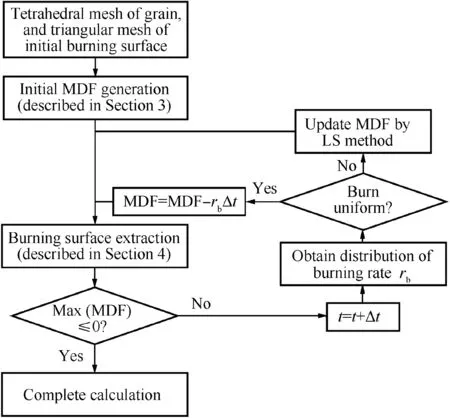
Fig. 2 Framework of burning surface regression simulation.
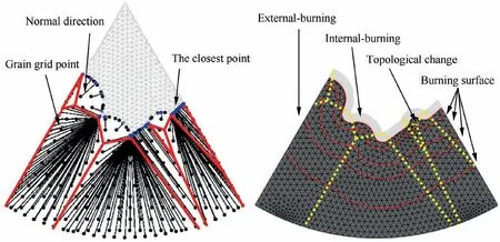
Fig. 1 Uniform burnback based on MDF method.
3. MDF calculation
3.1. Fundamental of minimum distance calculation
The significance of any MDF based method is the effective and accurate calculation of (un)signed distance between grain grid nodes and burning surface, which determine the performance of surface advancement. An effective method for computing the sign of distance has been reported, and this method can straightforwardly extend any algorithm for calculating the unsigned distance to calculating signed distance.Therefore,we aim at the acceleration of distance querying without making any difference between the cases of unsigned and signed.Without the loss of generality,we take the unsigned case as an example for discussion. Consider the given surface Ω and the space point P, where P=[P, P, P]∈Ris the coordinates of the given space point (for brevity, we name the space point by its coordinates in this paper), the unsigned distance between Pand Ω can be described as Eq. (4).

The analytical method can be used for the calculation of the minimum distance between given points and simple surfaces.However, as for complex surfaces, it is arduous to obtain the analytical solution. Polygons are always employed as the subset to illustrate the complex surfaces of objects in CAD. Arbitrary polygon is constituted of several triangles, by increasing the number of triangles, the accurate approximation of arbitrary surface can be implemented. Therefore, the minimum distance between points and a surface can be represented by the minimum distance between points and a triangular mesh.
The brute-force approach is the simplest method,which just traverses all triangles of the mesh to compute the distances of the point to each triangle, and then obtains the point-to-mesh distance by finding the minimum value of the above distances.Although the brute-force approach always exhibits a high accuracy,its calculation efficiency is not satisfactory.The computational complexity is O(mn),where m is the total number of points, n is the total number of triangles. Hence, brute-force approaches can only be chosen in case of small sets of triangles.
Herein,we present an effective method for the computation of point-to-mesh distance based on Equal Size Cube Voxels Structure (ESCVS). The basic idea of the ESCVS method is avoiding unnecessary computation of point-to-triangle distance according to the spatial regularity of the voxels structure.To achieve that, we partition the considered 3D space into smaller regions during the initial pre-computation step. Afterward,we only query the distance in the regions of the 3D space that are likely to contain the closest points instead of querying in the whole 3D space.
3.2. Efficient MDF calculation based on the ESCVS method
Consider the given triangular mesh (V, F) and space points P which nearby the mesh, where V=[V, V, V]∈Ris the coordinates matrix of the different triangle vertices, l is the total number of the different vertices, V,V,V∈Rcorrespond to x, y, z-coordinates, the ith vertex is represented as V=[V, V, V] (i=1, 2, ..., l). F ∈Ris the indices matrix of triangles,which stores three vertices indices for each triangle, n is the total number of triangles, the jth triangle is represented as F(j=1, 2, ..., n). P=[P, P, P]∈Ris the coordinates matrix of space points, P,P,P∈Rcorrespond to x, y, z-coordinates, m is total the number of space points, the kth space point is represented as P=[P, P,P] (k=1, 2, ..., m).
3.2.1. Equal size rasterization
In order to efficiently obtain the point-to-mesh distance,a rasterization operation is carried out on the considered 3D space to construct a data structure in which cells have the same side length s.A convenient way of rasterization is directly dividing the bounding-box by step s, where the bounding-box can be easily defined according to the maximum and minimum coordinate values of the considered units including points P and triangle vertices V. Nevertheless, the mentioned boundingbox usually cannot be exactly divided by the given Equal Size Cube Voxel (ESCV). Therefore, we expand the bounding-box along x, y, z-axis to achieve the exact division of it into equal size non-overlapping cubes, as shown in Fig. 3, and we called this operation as Equal Size Rasterization (ESR).
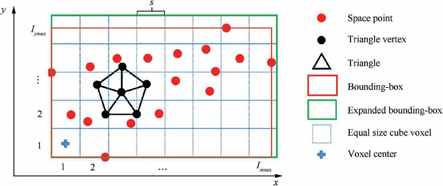
Fig. 3 ESR operation for given triangular mesh and space points.
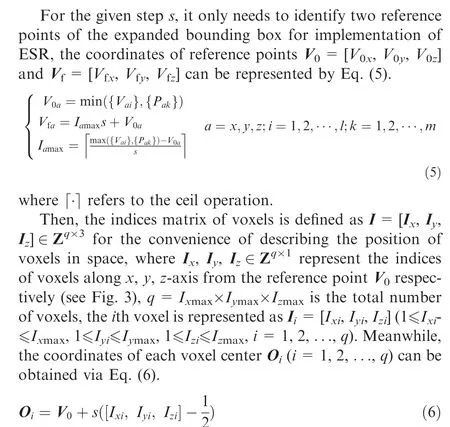
Owing to the spatial regularity of ESCV,for arbitrary given vertex or point Q=[Q,Q,Q],which is inside the expanded bounding-box,the index of the corresponding voxel I=[I,I, I], which contains Q, can be efficiently located by Eq.(7).


3.2.2. Voxel classification
To reduce unnecessary distance queries, we distinguish nonempty and empty voxels depends on whether the vertex of the triangle is contained in cube voxel. If there is at least one vertex of triangles that exists in the voxel, the voxel is defined as a non-empty voxel.While the empty voxels contain none of any vertex of each triangle. A fast way is proposed to implement voxel classification, and the algorithm flow is shown in
Algorithm 1.
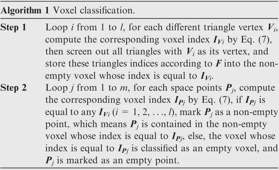
Algorithm 1 Voxel classification.Step 1 Loop i from 1 to l, for each different triangle vertex Vi,compute the corresponding voxel index IVi by Eq. (7),then screen out all triangles with Vi as its vertex, and store these triangles indices according to F into the nonempty voxel whose index is equal to IVi.Step 2 Loop j from 1 to m, for each space points Pj, compute the corresponding voxel index IPj by Eq. (7), if IPj is equal to any IVi(i=1,2,...,l),mark Pj as a non-empty point, which means Pj is contained in the non-empty voxel whose index is equal to IPj, else, the voxel whose index is equal to IPj is classified as an empty voxel, and Pj is marked as an empty point.
Obviously,all triangles are completely linked to the non-empty voxels after Step 1, the total number of non-empty voxels n(1≤n≤l)is equal to the total number of different voxel indices{I}({I}⊆{I},j=1,2,...,n;i=1,2,...,l).All empty voxels are classified,and space points are marked after Step 2.
Besides,there may be many regions in the expanded bounding box that we are not interested in,which caused by the mesh tilt. Thus, the voxels without any space points and vertices of triangles are straightforwardly eliminated to improve computing efficiency. The schematic diagram of voxel classification is shown in Fig. 4.
3.2.3. Situation of non-empty voxels
Non-empty and empty voxels have different properties, so we treat them differently. Conveniently, we call the triangle with the minimum distance from the given space point as the target triangle.
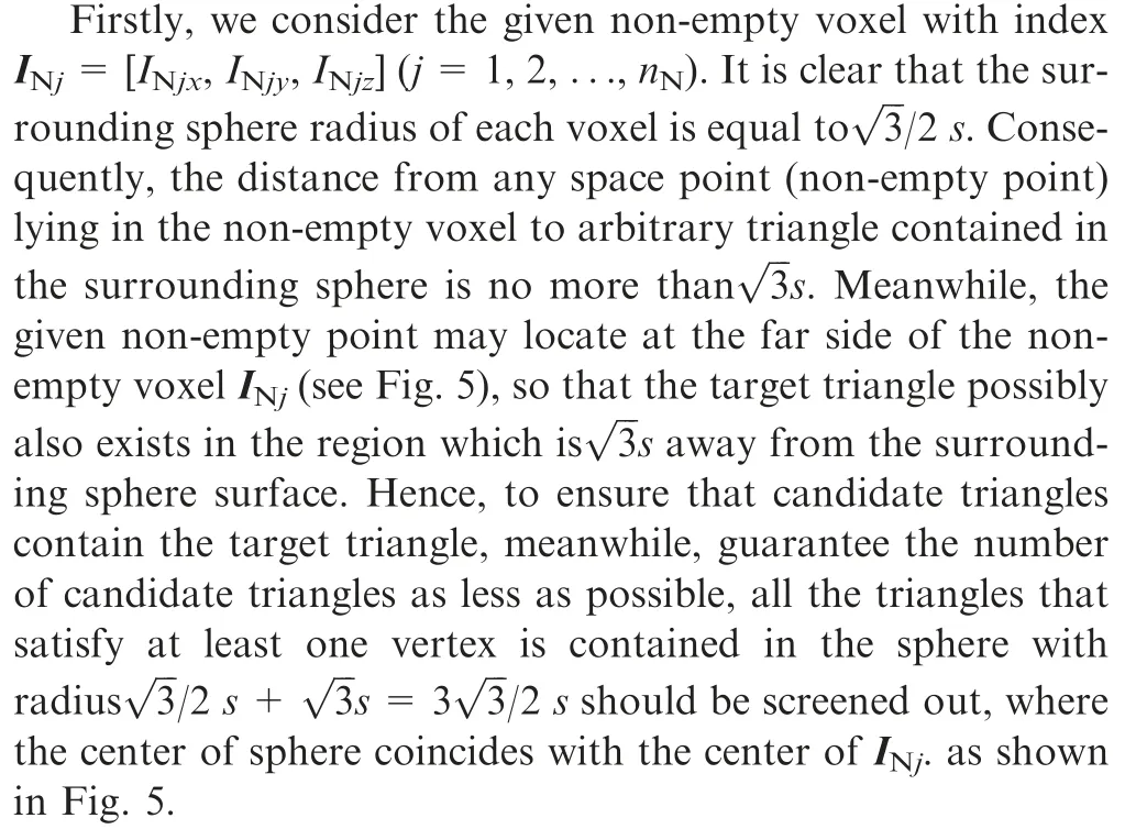
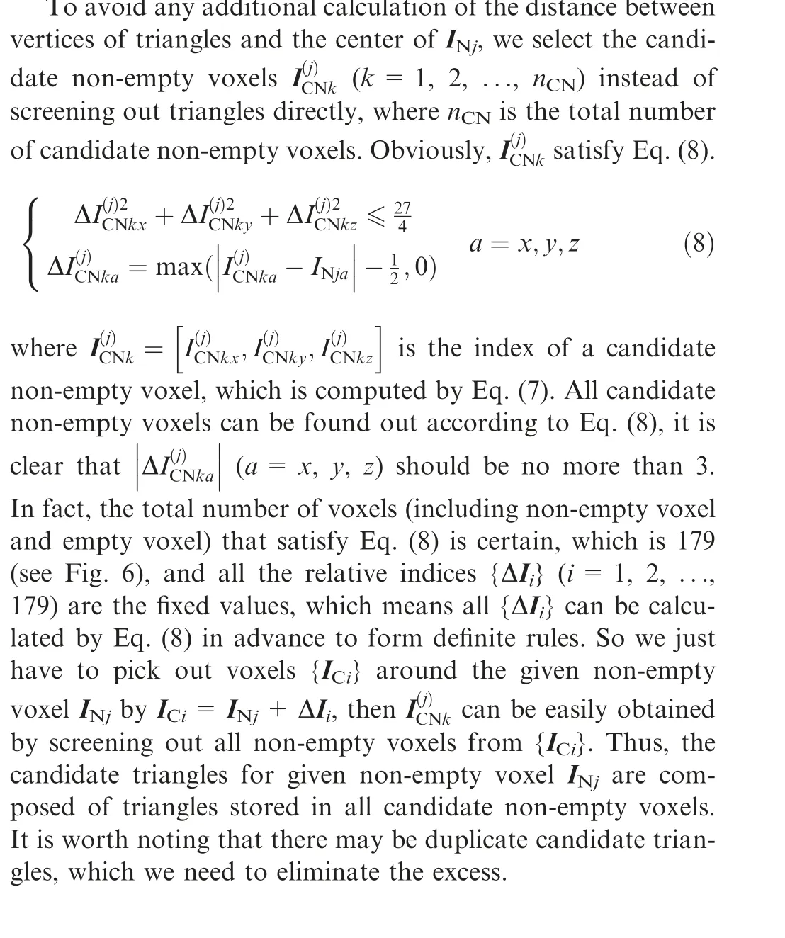
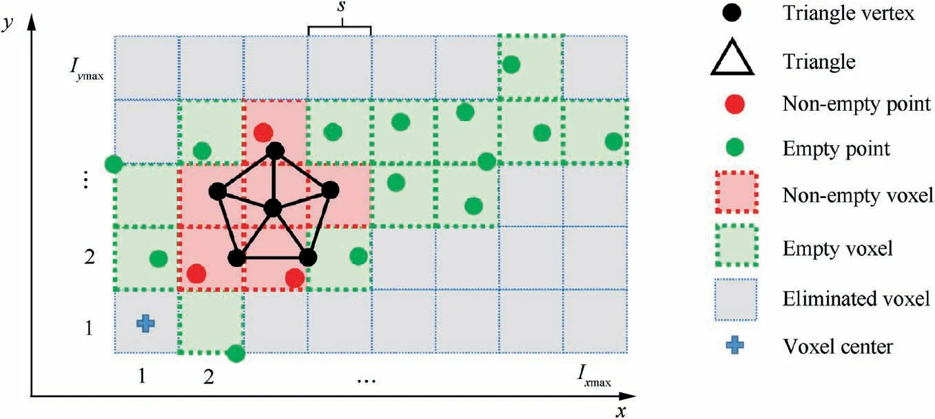
Fig. 4 Voxel classification.
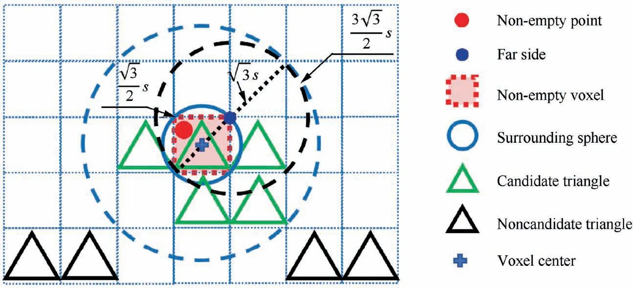
Fig. 5 Situation of non-empty voxel.
The summarized algorithm of candidate triangles screening for non-empty voxels situation can be denoted in Algorithm 2.
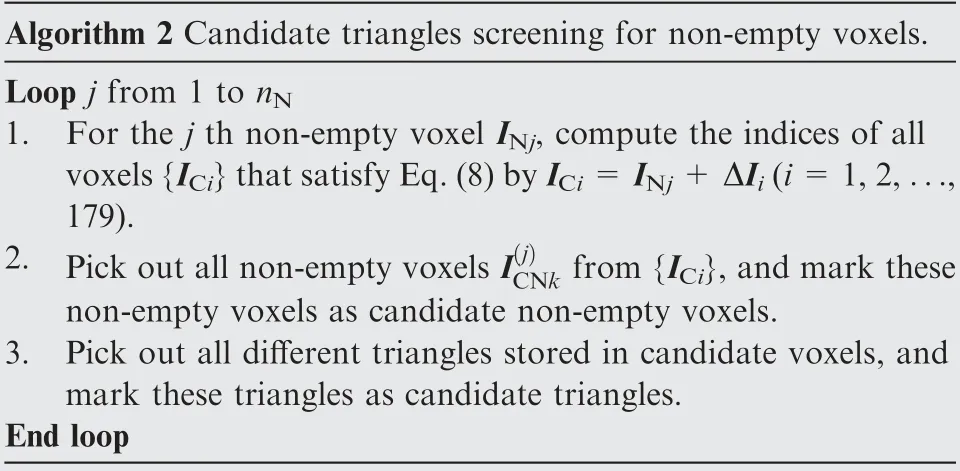
Algorithm 2 Candidate triangles screening for non-empty voxels.Loop j from 1 to nN 1. For the j th non-empty voxel INj, compute the indices of all voxels{ICi}that satisfy Eq.(8)by ICi=INj+ΔIi(i=1,2,...,179).2. Pick out all non-empty voxels I(j)CNk from{ICi},and mark these non-empty voxels as candidate non-empty voxels.3. Pick out all different triangles stored in candidate voxels, and mark these triangles as candidate triangles.End loop
3.2.4. Situation of empty voxels
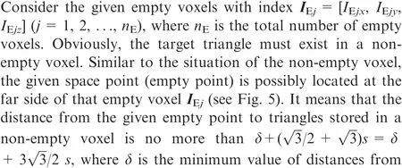
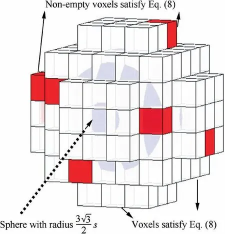
Fig. 6 Screening of candidate non-empty voxels.

Thus, non-empty voxels that satisfy Eq. (9) should be screened out as candidate non-empty voxels.

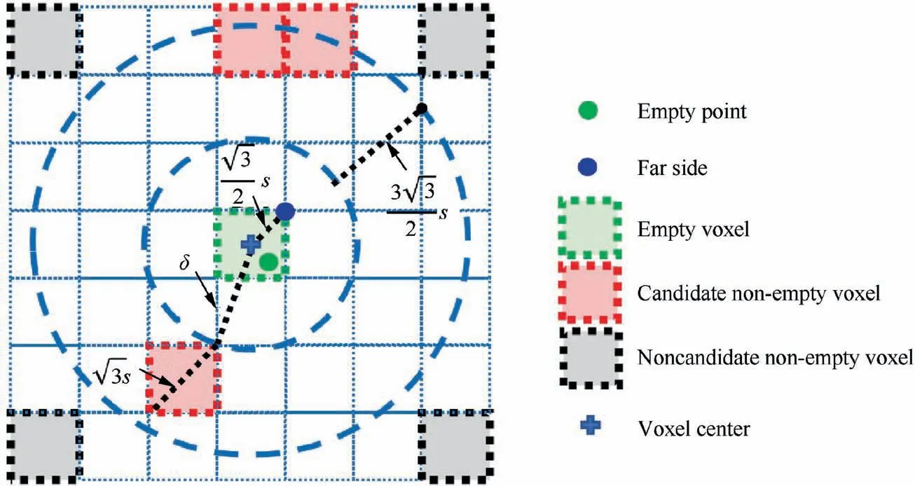
Fig. 7 Situation of empty voxel.
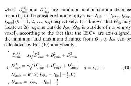
It is efficient to compute the minimum and maximum distances from Oto each non-empty voxel supported by Eq.(10), then the candidate non-empty voxels can be screened out by Eq. (9). Similarly, candidate triangles stored in these candidate non-empty voxels.
The summarized algorithm of candidate triangles screening for empty voxels situation can be denoted in Algorithm 3.
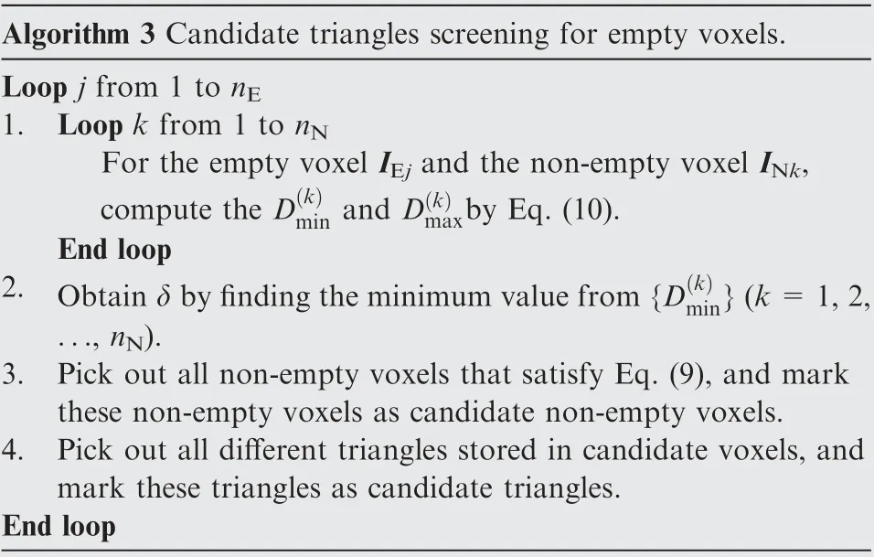
Algorithm 3 Candidate triangles screening for empty voxels.Loop j from 1 to nE 1. Loop k from 1 to nN For the empty voxel IEj and the non-empty voxel INk,compute the D(k)min and D(k)maxby Eq. (10).End loop 2. Obtain δ by finding the minimum value from{D(k)min}(k=1,2,..., nN).3. Pick out all non-empty voxels that satisfy Eq. (9), and mark these non-empty voxels as candidate non-empty voxels.4. Pick out all different triangles stored in candidate voxels, and mark these triangles as candidate triangles.End loop
Since non-empty voxels only locate closely to triangular mesh,the number of the non-empty voxels nis tiny, especially for the mesh of the initial burning surface. Non-empty voxels are concentrated in a narrow band.Consequently,the computation of the minimum and maximum distance from the vertex center to each non-empty voxels is fast.In addition,the above computation only needs to be done only once time at the initialization.
3.2.5. Summary of ESCVS method
ESCVS method mainly consists of two steps:(A)Initialization.(B)(Un)signed distance querying.In the initialization step,the rasterization step s, which is a user-specified parameter, is required to start the algorithm. Generally, s can be positively correlated to the number of triangles n, and we set up s to(0.5 ~1)nbased on a number of numerical testing in this paper. The reference point Vis obtained by Eq. (4) after ESR operation. Then all voxels and space points are classified based on the Algorithm 1 in Section 3.2.2, the Algorithm 2 in Section 3.2.3 is used to store candidate triangles for each non-empty voxel, and the Algorithm 3 in Section 3.2.4 for the situation of each empty voxels. Afterward, the initialization step is complete.
In (un)signed distance querying step, loop over each space point, if the space point is marked as non-empty point, compute the minimum value of distances to each candidate triangle stored in the corresponding non-empty voxel. Else, compute the minimum value of distances to each candidate triangle stored in the corresponding empty voxel.
The summarized algorithm flow of the ESCVS method is shown in Fig. 8.

Fig. 8 Algorithm flow of ESCVS method.
The computation of distance from a space point to a triangle can reference the reported method.Moreover, for the case of the signed distance calculation,which is the product of minimum distance and its sign, the sign of distance can be obtained based on the method in previous workeffectively,so we will not discuss in this paper.
4. Burning surface extraction
4.1. Marching tetrahedron method
Once the minimum distance from each node of grain tetrahedral mesh to the burning surface has been calculated, then we obtain the MDF.The burning surface extraction at the different burnt time or burnt web thickness can be described as the zero-level isosurface extraction of the MDF. Because 3D scalar field data records the information of tetrahedral mesh nodes, thus, we can obtain a series of contour points located on the edges of tetrahedral elements through interpolation,and then link these contour points by a specific rule for the formation of several non-overlapping triangles. Afterward, the isosurface is approximated by the triangular mesh.
The way of isosurface extraction via mesh can be generally divided into the Marching Cubes (MC) methodand the Marching Tetrahedron (MT) methodbased on the type of elements. In the MC method, there are 2=256 intersection patterns between isosurface and cube elements, and the ambiguity will appear while connecting each contour point by triangles at a specific situation. Compared to the MC method,the MT method is more facile to be implemented since there are only 2=16 intersection patterns exist. Furthermore, the MT method can avoid the ambiguity situation.The 16 intersection patterns can be classified into three kinds of surface-cell intersection cases, as shown in Fig. 9.
For a given tetrahedral element, where the scalar data is already calculated for each node, the scalar value at an arbitrary point Pin the tetrahedron can be calculated by Lagrange interpolation polynomial.Firstly,we defined the scalar volume coordinates L(i=1, 2, 3, 4) of Pin tetrahedron DDDDby Eq. (11).

where V(·) refers to the volume of the tetrahedron.
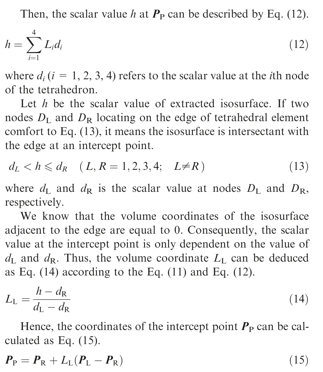
where Pand Pare the coordinates of nodes Dand D,respectively.
By carrying out Eqs. (14) and (15) on each edge of a tetrahedral element that comfort to Eq.(13),all intercept points on this tetrahedral element can be obtained, then, corresponding triangles are formed according to the case of surface-cell intersection shown in Fig. 9, where the connection rule of triangle vertices are predetermined and used in queries.All tetrahedral elements were treated by the described calculation above.Afterward,the burning surface can be obtained,and the burning surface area is equal to the sum of all extracted triangular area.
4.2. Improved marching tetrahedron method
The MT method has been well tested and widely used in isosurface extraction.Nevertheless, denser tetrahedral meshes are usually required to ensure the high precision of extraction.It will result in a tremendous increase in the number of tetrahedral elements involved in the calculation. Thus, the efficiency of the MT method is not satisfactory.
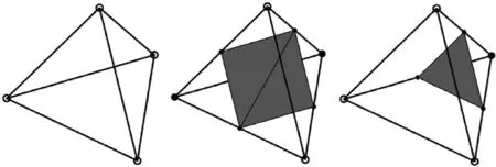
Fig. 9 Intersection between isosurface and tetrahedral element.
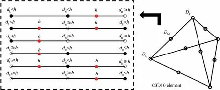
Fig. 10 Edge intersection of C3D10 element.
Increasing the order of a tetrahedral element is considered to be an effective way to enhance the accuracy of interpolation with less limitation of the mesh scale. It is owing to the excellent performance on both computational accuracy and efficiency, the second-order tetrahedral (C3D10) element is widely used in the Finite Element Method (FEM). Compared to linear tetrahedral (C3D4) elements, each C3D10 element possesses 10 nodes by adding midpoints of every edge. Thus,the brought quadratic in scalar field interpolation function will promote the accuracy of the computation. Nevertheless, there are 2=1024 types of intersection patterns between isosurface and the C3D10 element,and the number of formed triangles is much more than it in the C3D4 case.In order to balance the accuracy and efficiency of extraction computation, and reduce computational complexity,we present a simple method called Improved Marching Tetrahedron(IMT)method for isosurface extraction on the C3D10 element.
For the edge of C3D10 elements that intersect with the isosurface, the relationship between isosurface scalar value h and scalar values d, d, dat nodes D, D, Don edge respectively can be classified into 6 types, as shown in Fig. 10.
In this paper, the C3D10 elements are distinguished into two types: (A) Fine element: the intercept point number of each edge is no more than one. (B) Bad element: there exists at least one edge with two intercept points.
For the case of the fine element, it is similar to the calculation in the C3D4 case, and the intercept point can be directly obtained via Eqs. (14) and (15) according to the two adjacent nodes. This approach can be considered as a piecewise linear interpolation to the scalar field by using three nodes.As shown in Fig.11,the accuracy of the IMT method is higher than it of the MT method that using only two vertices and slightly lower than it of second-order interpolation method.
For the case of the bad element, the needed contour point should be obtained from the internal of the C3D10 element rather than the edge.To decrease the computational complexity of the internal contour point, we directly partition the C3D10 element into 8 non-overlapping C3D4 elements, then,calculate all the intersect points on C3D4 element and form corresponding triangles via the method mentioned in Section 4.1, thus, complex identifying of intersection patterns is avoided. The schematic diagram of isosurface extraction is shown in Fig. 12.
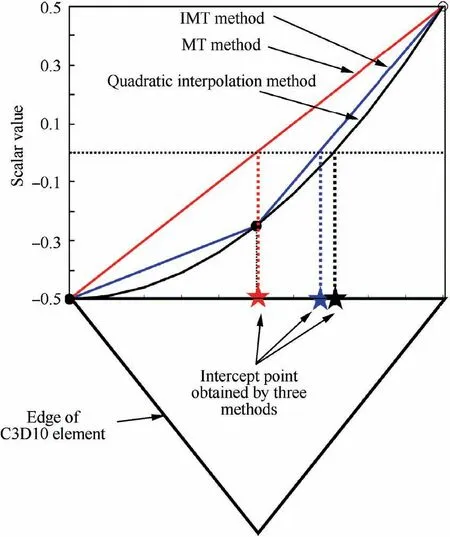
Fig. 11 Three interpolation methods.
In actual computation, the tetrahedral elements intersected to the isosurface are only aggregate in a narrow region.Therefore,it is unnecessary to consider the vast majority of tetrahedral elements during computation. These C3D10 elements satisfied that the minimum MDF value of 10 nodes is larger than zero or the maximum MDF values of 10 nodes is smaller than zero are ignored during computation, it means that there is no intersection between the burning surface and the C3D10 element. When the unnecessary tetrahedral elements are eliminated, the number of C3D10 using in the computation of burning surface extraction will be remarkably reduced. Thus,the rate of computation is boosted.
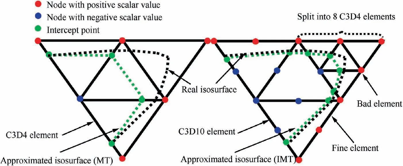
Fig. 12 Schematic diagram of isosurface extraction.
To sum up,the IMT method can be denoted in Algorithm 4.
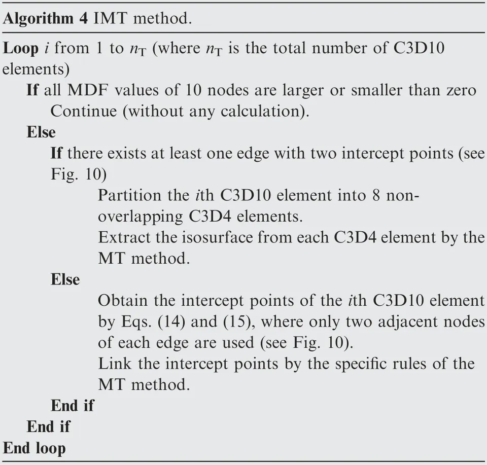
Algorithm 4 IMT method.Loop i from 1 to nT (where nT is the total number of C3D10 elements)If all MDF values of 10 nodes are larger or smaller than zero Continue (without any calculation).Else If there exists at least one edge with two intercept points(see Fig. 10)Partition the ith C3D10 element into 8 nonoverlapping C3D4 elements.Extract the isosurface from each C3D4 element by the MT method.Else Obtain the intercept points of the ith C3D10 element by Eqs. (14) and (15), where only two adjacent nodes of each edge are used (see Fig. 10).Link the intercept points by the specific rules of the MT method.End if End if End loop
5. Results
5.1. Computational environment
In this section, the performance of our method was tested in uniform burnback cases,including star grain and finocyl grain with various geometry parameters, and the case of nonuniform tube grain was also investigated. We modeled the grain geometry by CREO (a popular commercial CAD software), and the initial burning surfaces can be easily exported to STL format files. Then the tetrahedral mesh constructed by C3D10 elements was generated by a mesh generator based on the MATLAB function ‘‘generateMesh” from the Partial Differential Equation Toolbox (an automatic 3D tetrahedral mesh generator that accepts input from Boundary Representations (BRep) from the STL file format). The MDF computational code was written by Visual C++ 14.0 and accelerated by parallel function from LIBIGL (a simple C++ geometry processing library). MATLAB R2019a was used to run the grain burnback simulation program, and the module written in C++ was wrapped into MEX files for MATLAB. All results were gotten on a laptop PC running a Windows 10 operating system with a 2.60 GHz Intel Core i7-6700HQ processor and 16 GB of RAM.
5.2. Star grain
We selected star grain as a computational case owing to its certain analytical solution so that the accuracy of our method can be easily verified. We compare the performance between the IMTBSR method and the linear MT method by fixing the number of nodes (MTBSR1) and tetrahedron (MTBSR2).
We perform the validation of three cases for star grain with different star-angle number n,and the geometry illustration is shown in Fig. 13, where the grain length L=1560 mm, other parameters have been presented in Table 1.
When the grain is axisymmetric, the simplification can be operated on the grain geometry model, dramatically promote the efficiency of calculation.In the cases of star grain,we only do the burnback computation for 1/(2 n) of grain. The number of discrete points of burnt web thickness was set as 100.
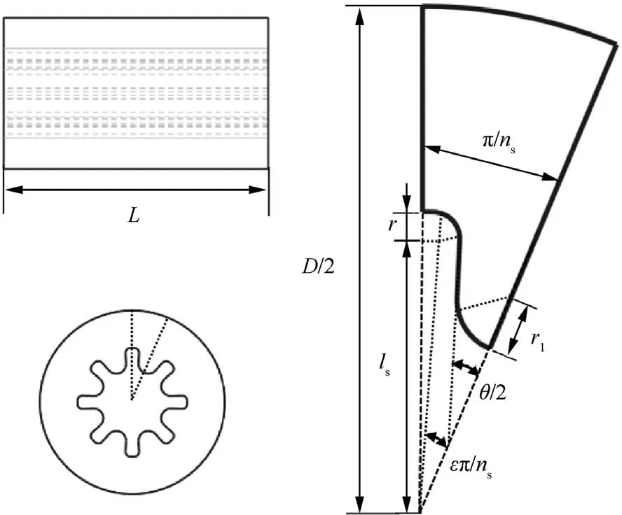
Fig. 13 Configuration of star grain.

Table 1 Parameters of star grain.

Fig. 14 Distance contours of star grain.
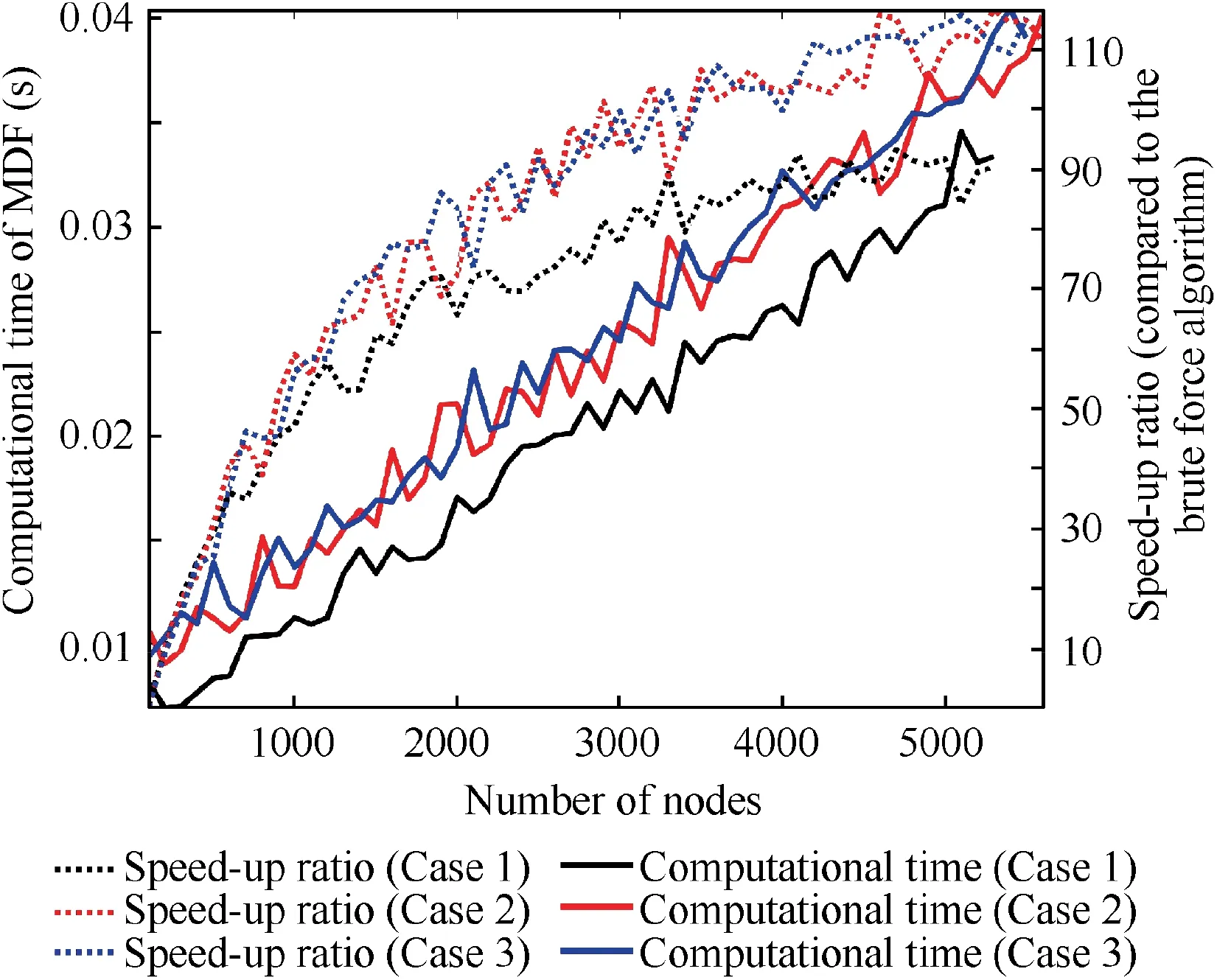
Fig. 15 Computational time of MDF vs number of nodes.
Fig. 14 presented the minimum distance contours of grain.For the minimum distance computation, when the number of grid nodes is around 5000, the consumed computational time is no more than 0.04 s. The high efficiency can be attributed to the pre-partition of grain geometry by the ESCVS method since the pre-partition leads to the remarkable elimination of triangles that unnecessary to be computed. In addition, as shown in Fig. 15 the relationship between computational time after pre-partition and number of nodes is basically linear,and the speed-up ratio compared to the brute force algorithm is close to 100 when the number of nodes is large. So the efficiency of burnback computation can be improved remarkably.
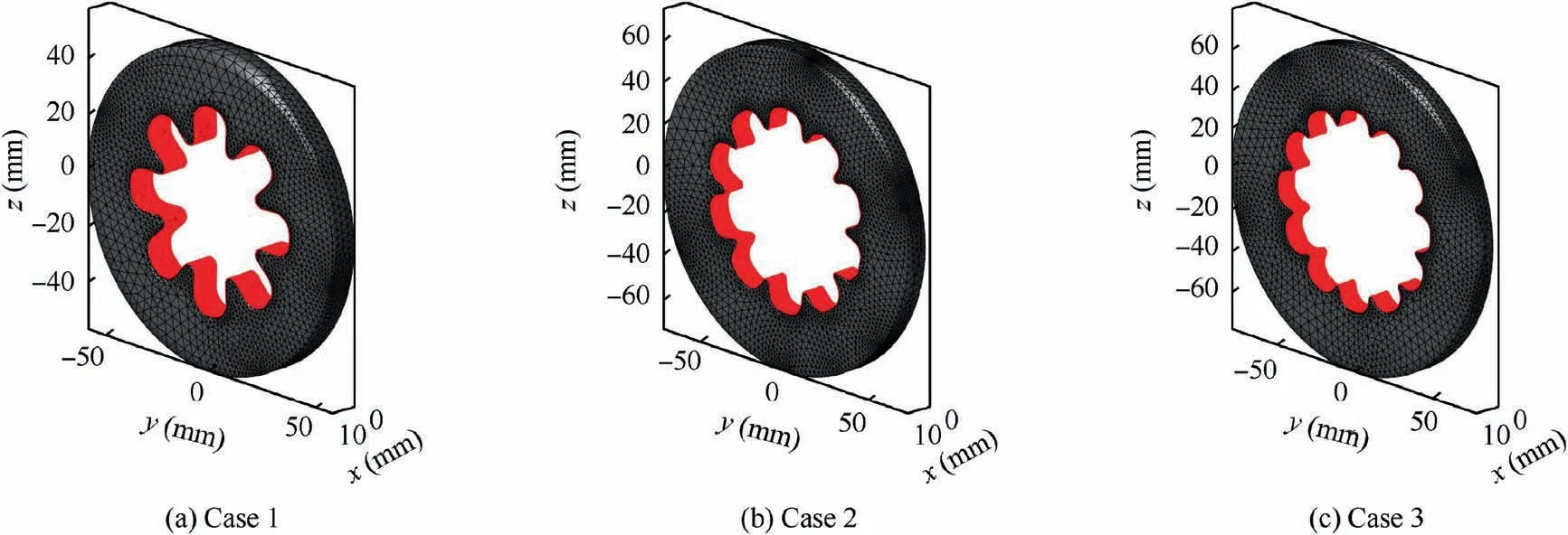
Fig. 16 Burning surface of star grain (burnt web thickness h=10%hmax).
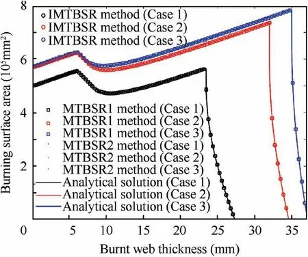
Fig.17 Burning surface area vs burnt web thickness(star grain).
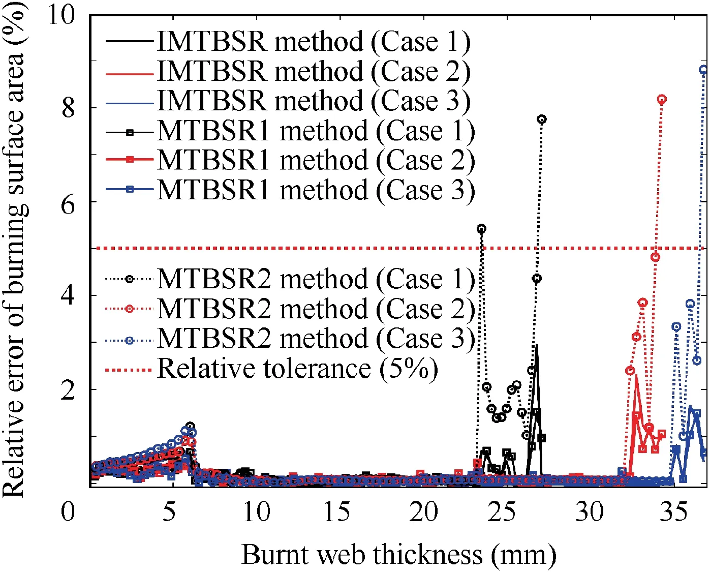
Fig. 18 Relative error of burning surface area vs burnt web thickness (star grain).
The burning surface illustration of three kinds of star grain under assigned burnt web thickness is shown in Fig.16,where his the maximum burnt web thickness. According to the burning surface area vs burnt web thickness (see Fig. 17), the computational result of IMTBSR method and MTBSR1 with same nodes number show an insignificant Relative Error(RE)with respect to the analytical solution (≤2%), moreover, in stationary burning phase, the RE is even lower than 0.2%.For MTBSR2,though the RE is more than 5%at the burning tail phase, it exhibited an extraordinary accuracy in the stationary burning phase (see Fig. 18). Because the burning area is near to zero in the burning tail phase, and the size of the tetrahedral elements which is close to the surface of the combustion chamber case is not small enough,it leads to an apparent deviation between isosurface obtained by linear interpolation and the actual burning surface. Consider that the burning surface extraction is carried out on the MDF scalar field of grain tetrahedral mesh. Obviously, there are two ways to improve the accuracy of burning surface extraction:(A) improving the accuracy of MDF calculation which requires to refine the triangular mesh of initial burning surface;(B) limiting the maximum element size of grain tetrahedral mesh, which avoid using large triangles to approximate the burning surface.
As shown in Table 2,when the IMTBSR method possesses a similar accuracy with the MTBSR1 method, our method only takes 0.63 s on burning surface extraction, which is approximately equal to 79%of MTBSR1 computational time.This is mainly due to the number of the tetrahedral elements,where the number in MTBSR1 is 7 times more than it in the IMTBSR method. The isosurface around the tetrahedral element is considered to be gentle if there is no more than one intersect point on each edge of the tetrahedral element, therefore,the further subdivision of the tetrahedral show negligible improvement on computational accuracy,but brings the extension of computational time. On the other hand, the MTBSR2 method is faster than the IMTBSR method. However, the accuracy is quite low in the burning tail phase. Generally,the IMTBSR method balanced the accuracy and efficiency promisingly.
5.3. Finocyl grain
The examples mentioned in Section 5.2 only contain the situation of lateral-burning but without cigarette-burning. Hence,we simulated the method on finocyl grain,which include above two kinds of burning type. The relation between burning surface area and burnt web thickness of finocyl grain is difficult to formulate analytically due to the high complexity of the 3D grain configuration. Therefore, to verify the effectiveness of the IMTBSR method in the case of finocyl grain,the simulated result was compared with the CAD method.The configuration of finocyl grain is presented in Fig. 19, in which forward and backward dome are both ellipsoidal, the aspect ratio is 2.5,the thickness and fillet radius of each fin are all equal.The fixed parameters are assumed as D=1000 mm, D=200 mm, D=400 mm, L=1800 mm, L=1400 mm,L=1600 mm, L=10 mm, R=150 mm, R=200 mm,R=473.6 mm, R=5 mm, and the rest geometry parameters are listed in Table 3, where nis the number of fins.
It is shown in Figs.20-23 that,despite the high complexity of the 3D grain structure,the IMTBSR method still maintains a good performance on accurate computation.Compared with the CAD method, the RE is less than 2.5%. According to Table 4,the total computational time of CAD method reaches98 s,while our method only took about 4 s,including the time of automatic 3D grain triangulation. It indicates that our method allowed a dramatic enhancement on computational efficiency in uniform burning regression simulation with various 3D grain configuration.

Table 2 Mesh information and computational time (star grain).
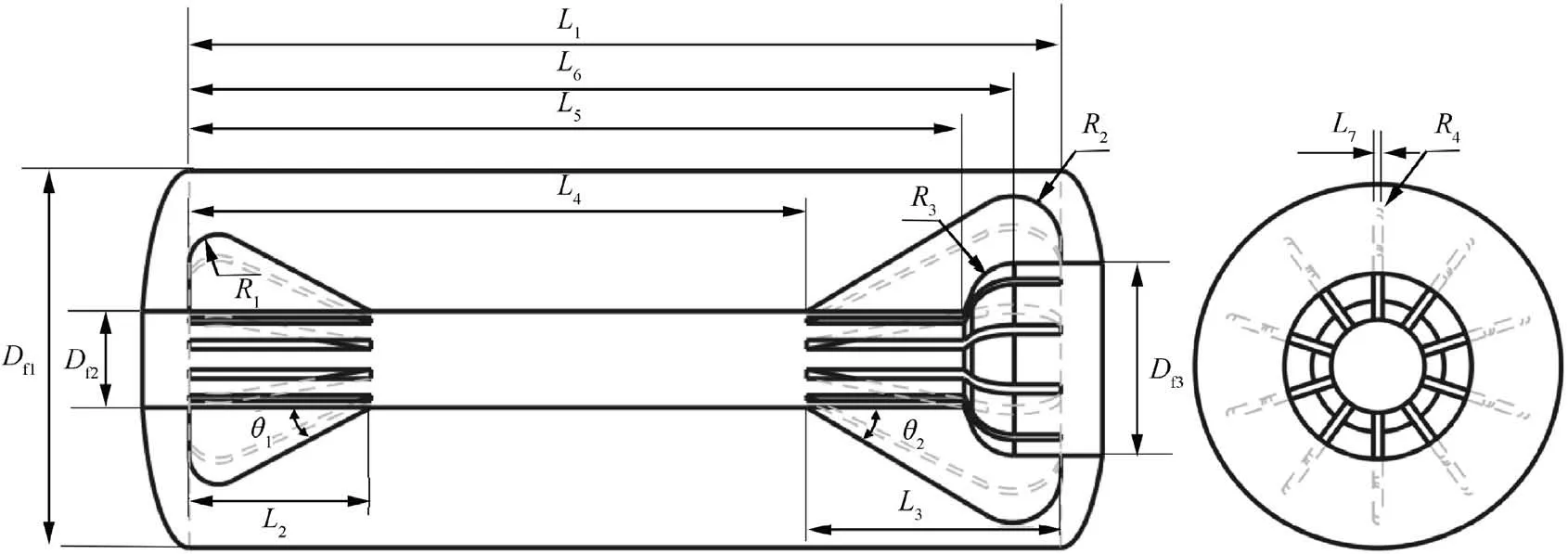
Fig. 19 Configuration of finocyl grain.

Table 3 Parameters of finocyl grain.

Fig. 20 Distance contours of finocyl grain.

Fig. 21 Burning surface of finocyl grain (burnt web thickness h=55%hmax).
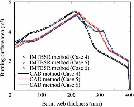
Fig. 22 Burning surface area vs burnt web thickness (finocyl grain).
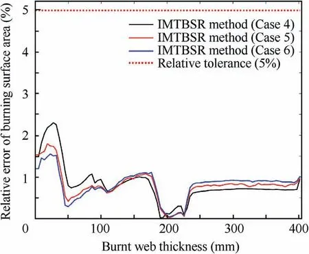
Fig. 23 Relative error of burning surface area vs burnt web thickness (finocyl grain).
5.4. Non-uniform tube grain
In this section, we aim to verify the correctness of the unified framework for non-uniform burning surface regression simulation,where ESCVS method is used to provide the initial MDF for LS method, and IMTBSR method is used to extract the burning surface on the updated MDF by LS method.
The non-uniform tube grain with two kinds of normal burning rate from Ref.is employed for testing (see Fig. 24), where the analytical solution of the sample grains can be summarized by burning surface area versus burnt web thickness functions as Eq. (16).
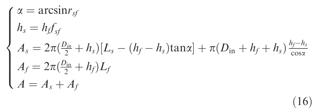
where hand hare the burnt web thickness of slow and fast burning parts, respectively, Aand Aare the burning surface area of slow and fast burning parts,respectively,A is the total burning surface area, rrefers to the ratio of slow and fast burning rate.
Since the burnback rate distributes discontinuously, the capability of strong discontinuity is able to be validated for the surface tracing method. The geometric profile of the tubegrain is shown in Fig. 24, where L=L=500 mm,D=500 mm, D=200 mm, r=0.7. The PDE of the LS was solved by Nodal Discontinuous Galerkin Finite Element (NDGFE) methodbased on the unstructured mesh of C3D10 elements. We integrated the equations forward in time with the CFL constrained time step by using the thirdorder Total Variation Diminishing (TVD) Runge-Kutta(RK) scheme. The number of C3D10 elements for 3D grain mesh is set to 12904, and the number of nodes is 19869.

Table 4 Parameters of finocyl grain.
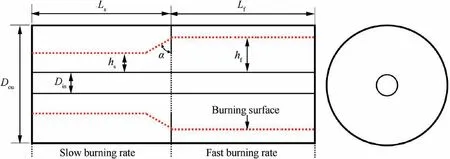
Fig. 24 Configuration of non-uniform tube grain.

Fig. 25 Burning surface at various burnt web thickness (non-uniform tube grain).
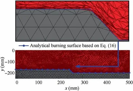
Fig.26 Slope from fast burning part to slow burning part(nonuniform tube grain).
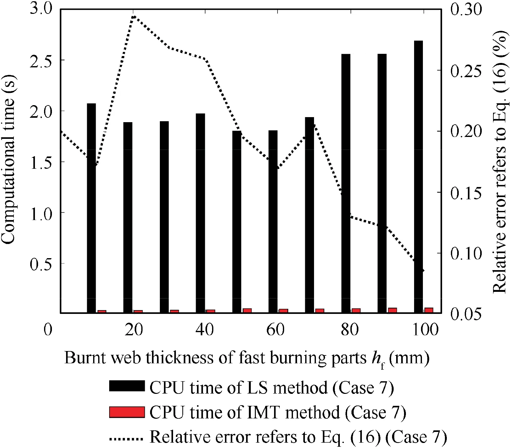
Fig. 27 Relative error vs burnt web thickness of fast burning parts hf and computational time at each hf (non-uniform tube grain).
The simulation result is in good accordance with the theoretical result that there is a slope from the fast burning part to the slow burning part (see Figs. 25 and 26) in the area with a discontinuous burning rate. The above phenomenon can be precisely captured via the IMTBSR method and the RE of the burning surface area between the IMTBSR method and the analytical solution based on Eq. (16) is no more than 0.3%(see Fig.27).It indicates that the ESCVS and LS method in this paper works correctly,and the surface tracing method is capable of handling the strong discontinuity. Meanwhile, for the grain mesh with 12904 C3D10 elements and 19869 nodes,the computational time of the burning surface extraction by the IMTBSR method is no more than 0.05 s. Hence, by integrating with the LS method, the IMTBSR method has the potential to handle the case of non-uniform combustion accurately and effectively,even when the burning rate is discontinuous with the spatial distribution.
6. Conclusions
A rapid method for the solid propellant grain burnback simulation of SRM on the second-order unstructured tetrahedral mesh is developed in this paper. The framework can be easily implemented to handle the cases of uniform and non-uniform burning by nesting the MDF and LS method. In the uniform burning case, solving PDE is eliminated to remarkably reduce the computational time.And the in non-uniform burning case,the LS method is employed to update the MDF at an arbitrarily distributed burning rate,where the LS method can be easily replaced with a more efficient method. The result shows that the ESCVS method exhibits a noble performance on the computation of initial grain MDF for the presented testing cases.Furthermore, the IMTBSR method improves the computational efficiency of burning surface extraction from updated MDF and simultaneously possesses satisfactory accuracy.Such a strategy can find the general applicability in the grain with a complex geometry profile.
Declaration of Competing Interest
The authors declare that they have no known competing financial interests or personal relationships that could have appeared to influence the work reported in this paper.
Acknowledgement
sThis work was supported by the National Natural Science Foundation of China (No. 11202224).
 CHINESE JOURNAL OF AERONAUTICS2021年4期
- CHINESE JOURNAL OF AERONAUTICS的其它文章
- Time delay compensation in lateral-directional flight control systems at high angles of attack
- Dual stability enhancement mechanisms of axial-slot casing treatment in a high-speed mixed-flow compressor with various tip clearances
- Development cost prediction of general aviation aircraft using combined estimation technique
- Improvement on shaped-hole film cooling effectiveness by integrating upstream sand-dune-shaped ramps
- Modeling and parameter identification of linear time-varying systems based on adaptive chirplet transform under random excitation
- An experimental method to obtain the hard alpha anomaly distribution for titanium alloy aeroengine disks
