Interference and grinding characteristics in ultraprecision grinding of thin-walled complex structural component using a ball-end grinding wheel
Tingzhang WANG, Henan LIU, Chunya WU, Jian CHEN, Mingjun CHEN
Center for Precision Engineering, Harbin Institute of Technology, Harbin 150001, China
KEYWORDS Ultra-precision grinding;Complex component;Ball-end grinding wheel;Interference;Grinding characteristics
Abstract As for ultra-precision grinding of difficult-to-process thin-walled complex components with ball-end grinding wheels,interference is easy to occur.According to screw theory and grinding kinematics, a mathematical model is established to investigate the interference and grinding characteristics of the ball-end wheel. The relationship between grinding wheel inclination angle, C axis rotation angle,grinding position angle and grinding wheel wear are analyzed.As the grinding wheel inclination angle increases, the C axis rotatable range decreases and the grinding position angle increases. The grinding position angle and wheel radius wear show a negative correlation with the C axis rotation angle. Therefore, a trajectory planning criteria for increasing grinding speed as much as possible under the premise of avoiding interference is proposed to design the grinding trajectory. Then grinding point distribution on the ball-end wheel is calculated, and the grinding characteristics, grinding speed and maximum undeformed chip thickness, are investigated. Finally,a complex structural component can be ground without interference, and surface roughness and profile accuracy are improved to 40.2 nm and 0.399 μm, compared with 556 nm and 3.427 μm before ultra-precision grinding. The mathematical model can provide theoretical guidance for the analysis of interference and grinding characteristics in complex components grinding to improve its grinding quality.
1. Introduction
Complex structural components are widely applied in the fields of optics, aerospace, national defense and electronics due to their excellent mechanical, optical and dynamic properties,showing a development trend of miniaturization, structural complexity and increasing processing requirements.The materials of these components are mainly hard and brittle materials that are difficult to process, such as engineering ceramics,glassand semiconductor.These factors together increase the processing difficulty of these complex structural components. Ultra-precision grinding is a promising method to improve machining accuracy and surface quality, taken to be the machining chain end or to reduce the subsequent polishing pressure.For example, a Ψ-shaped fused silica thinwalled component is a typical complex structural component,which is a core device in the aerospace navigation system,and its processing quality directly determines the navigation accuracy and service life of the navigation system.
For ultra-precision grinding of hard and brittle materials,research focuses on material removal mechanisms,subsurface damageand surface roughness.Through studying the interaction mechanism between abrasive particles and the workpiece, the ductile domain grinding of hard and brittle materials can be achieved to obtain an ultra-smooth surface and reduce the subsurface damage depth. However, for the ultra-precision grinding of the complex structural component,the interference between the grinding tool and workpiece, and the choice of the machining mode are the first considerations in the machining process.
When interference occurs in the processing of complex components, it not only affects the machining accuracy but also causes the workpiece to be broken and affects the machining efficiency. According to the collision mechanism between the grinding wheel and the workpiece, interference can be divided into two aspects:global interference and local interference.Global interference mainly refers to the collision of the grinding wheel rod and non-grinding area of the grinding wheel with the workpiece, which is directly related to the processing mode,the motion system of the machine,and the structural dimensions of the grinding wheel and workpiece.Especially for the machining of concave surfaces,global interference is necessary to be checked.Local interference is mainly the removal of material from the workpiece by the non-current grinding area of the grinding wheel, which will have a serious impact on the surface accuracy of the ground workpiece.This kind of interference is very easy to occur when grinding aspheric and free-form surfaces with sharp changes in curvature radius. Existing research work on interference mainly focuses on interference detection, iterative analysis and physical modeling analysis to avoid interference, and systematic mathematical modeling analysis is rarely used. In this work,based on fully analyzing the structure of complex components and grinding kinematics, a mathematical analysis model is established to study the interference characteristics in the grinding process.
For the ultra-precision grinding of complex structural components and free-form surfaces, research and selection of appropriate grinding modes have been one of the research hotspots. With the development of processing technology and machine tool technology and the improvement of machine tool accuracy, free-form surface grinding modes have mainly experienced cross-axis grinding,inclined grinding,parallel grinding and wheel normal grinding.Cross-axis grinding was first applied to grind large convex or shallow concave surfaces,with the grinding wheel axis perpendicular to the workpiece rotation axis.Cross-axis grinding can be achieved by simultaneous movement of two axes,which makes the required grinding machine tool structure relatively simple. However, the disadvantage of cross-axis grinding is that the length of the grinding wheel rod needs to be larger than the radius of the workpiece when grinding the concave surface, which makes the dynamic characteristics of the grinding system poor and deformation of the grinding wheel to affect the grinding accuracy. But crossaxis grinding is still an effective method for aspheric grinding.According to the problems of cross-axis grinding,Suzuki et al.proposed the inclined grinding mode in 1998 to shorten the grinding wheel shaft length, increase the grinding system rigidity,and improve the grinding accuracy. In inclined grinding, the grinding wheel axis is inclined at a certain angle (usually 45°)relative to the workpiece axis,and the complex curved surface grinding can be achieved by two-axis linkage.The contact line on the grinding wheel surface is a complicated three-dimensional curve, making the grinding wheel produce non-uniform wear and increasing the difficulty of error compensation.
Grinding wheel life is closely related to ultra-precision grinding efficiency and processing accuracy, so Saeki et al.developed the parallel grinding method to prolong the grinding wheel life. The ball-end grinding wheel and the workpiece are still relatively inclined at a certain angle and can be driven by two axes to achieve relative movement, enabling the grinding wheel speed direction parallel to the workpiece speed direction at the contact point.During grinding, the contact point moves along the grinding wheel profile, which prolongs the grinding wheel life and simplifies the error compensation.However, the ground workpiece profile accuracy is sensitive to the grinding wheel profile accuracy. Hence, high-precision dressing of the grinding wheel is necessary.Based on the analysis of parallel grinding characteristics,Tohmeimproved the parallel grinding and proposed the wheel normal grinding method, in which the grinding point keeps invariant to avoid the grinding wheel profile error transferring to the workpiece.This grinding process requires a three-axis movement to achieve, and these three axes can be two linear axes and one rotation axis, or three linear axes. Chen et al.adopted two linear axes and one rotation axis to grind a small aspheric surface. In this grinding mode, the active arc center of the grinding wheel needs to be precisely adjusted to the rotation center of the rotation axis to avoid the eccentricity that affects the machining accuracy. Yan et al.used the three linear axes method to grind the small aperture aspheric surfaces and obtained high profile accuracy.For this method,the trajectory planning for the three axes is relatively difficult. The research work on grinding mode is mainly about exploring the ideal grinding mode for different components and using experimental methods to study the influence of grinding mode on processing quality. However, there is no systematic exploration of the influence mechanism of grinding mode on grinding quality. By considering the structural characteristics of the Ψshaped thin-walled component and limited processing space,the parallel grinding method is adopted for ultra-precision grinding.Through the establishment of a mathematical analysis model, the distribution of grinding points on the ball-end grinding wheel is investigated to analyze its grinding characteristics during the parallel grinding of the complex component.It is expected that the analysis of the grinding characteristics can help to study the influence mechanism of grinding mode on grinding quality.
Henceforth, this work is organized to investigate the interference and grinding characteristics in thin-walled complex component grinding with the ball-end grinding wheel. Based on the kinematic analysis of the grinding process and screw theory,a mathematical analysis model of the collision between the grinding wheel and workpiece is established to study the kinematic limit condition to avoid interference. According to this model, the grinding point distribution on the ball-end grinding wheel and wear characteristics of the grinding wheel are analyzed. By considering trajectory planning criteria for increasing grinding speed as much as possible under the premise of avoiding interference, and a grinding scheme for complex components is designed. Then the relative speed between the grinding wheel and workpiece and the maximum chip thickness at different grinding positions are analyzed to study the grinding characteristics of complex components. Finally,ultra-precision grinding experiments are performed on the Ψshaped complex component to verify the feasibility and effectiveness of the proposed grinding method.
2.Theoretical study of interference between complex component and grinding wheel
The Ψ-shaped component is a typical thin-walled complex component and is composed of a center rod and a thinwalled spherical shell, of which the caliber is 30 mm, wall thickness is 0.9 mm, and the minimum curvature radius is 2 mm, as shown in Fig. 1(a)). This component has high processing requirements, profile accuracy is less than 0.5 μm,and surface roughness is less than 5 nm. Therefore, it is a typical complex and difficult-to-process component,and the combination of ultra-precision grinding and polishing is the ideal processing method. In the grinding process, the machining of the small-sized round corner is difficult to realize, and the interference between the workpiece and the grinding wheel can easily cause the thin-walled spherical shell to be broken.The small ball-end grinding wheel is adopted to grind the round corner, and the grinding wheel is tilted and can rotate with C turntable around Z axis to realize non-interference grinding (see Fig. 1(b)). Hence, it is necessary to study the interference characteristics of the Ψ-shaped component grinding to determine the limit conditions of non-interference movement and the grinding characteristics to improve the grinding quality.
Since the Ψ-shaped component is mainly composed of a spherical surface and round corner, the avoidance of the local interference is related to the choice of the size of the ball-end grinding wheel. According to the Dupin indicatrix, Yoonproposed a criterion for local interference as follows:in Fig.1(c)and(d).However,when grinding the external surface,it is easy to cause the collision between the grinding wheel and the shell and the cylindrical part of the grinding wheel to participate in the grinding (see Fig. 1 (e) and (f)).
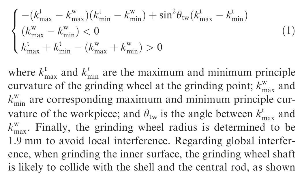
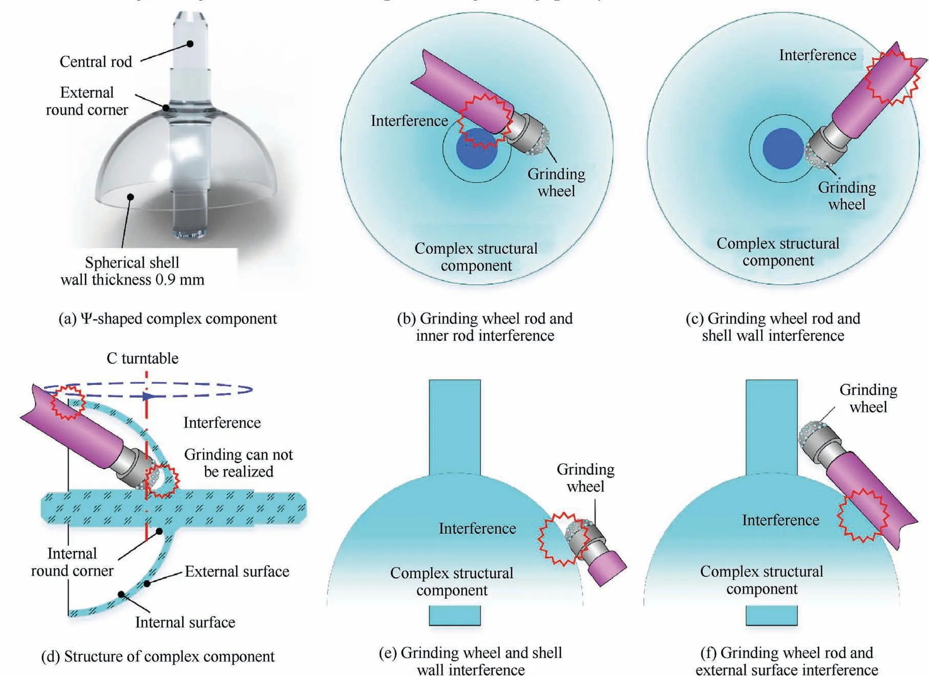
Fig. 1 Structure of Ψ-shaped complex component and interference between grinding wheel and workpiece.
2.1.Mathematical model of interference in grinding the complex component
2.1.1. Mathematical model of interference
According to the grinding kinematic analysis and screw theory,a mathematical model of collision is established to further study the global interference. In the grinding kinematic chain, there are three coordinate systems, namely workpiece coordinate O(x, y, z), grinding wheel coordinate O(x,y, z), and reference coordinate O(x, y, z), among which the grinding wheel coordinate coincides with the reference coordinate, as shown in Fig. 2. Hence, the transformation matrix of the grinding wheel coordinate to the reference coordinate is
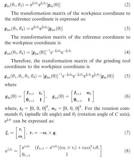
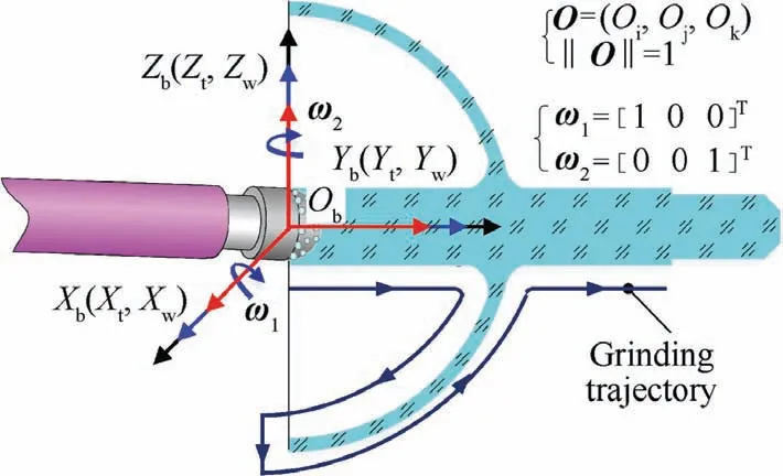
Fig. 2 Coordinate system of interference mathematical analysis model for grinding complex components.
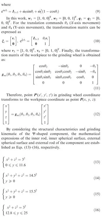
In the grinding wheel coordinate, the mathematical expression of the ball-end, cylindrical section and shaft can be expressed as follows, respectively.
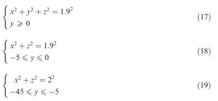
Then, the mathematical expression of each part of the grinding wheel is transformed into the workpiece coordinate to solve the motion conditions of the collision between the grinding wheel and workpiece. Finally, the limit kinematic condition of the component grinding can be obtained.
2.1.2. Mathematical model of grinding point distribution
When studying the grinding characteristics of ball-end grinding wheels, such as grinding speed and maximum undeformed chip thickness,it is necessary to study the distribution of grinding points on the ball-end grinding wheel.During the establishment of the grinding point distribution mathematical model,the workpiece coordinate needs to be transformed to the grinding wheel coordinate, and the transformation matrix is expressed as:
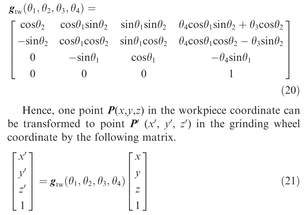
The ball-end grinding wheel needs to move along the profile line of the Ψ-shaped component to realize the component grinding. The profile line can be divided into six sections,namely inner rod, inner round corner, inner spherical surface,external spherical surface, external round corner and external rod,and in the workpiece coordinate the mathematical expression of machining trajectory can be described by Eqs. (22)-(27), respectively.
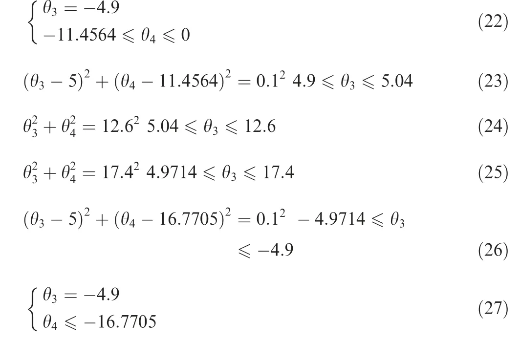
In the grinding wheel coordinate, the mathematical expression of the ball-end grinding wheel is

Then,the grinding trajectory in the workpiece coordinate is transformed into the grinding coordinate,and the distribution of grinding points on the ball-end grinding wheel can be obtained. Here, taking the inner spherical surface grinding as an example,the obtained distribution coordinates of the grinding points on the ball-end grinding wheel are as follows.
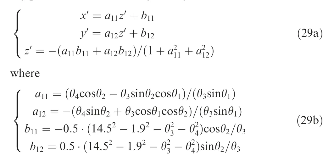
2.2. Analysis of interference characteristics in the grinding of complex components
The inclination angle of the grinding wheel spindle and the rotation angle of the C turntable are the main factors affecting the interference in the grinding process. According to the established mathematical model of interference,the influence of these two factors on interference is obtained and shown in Fig. 3. A,B,C and D in the figure define the extreme points of the rotatable region of C axis. In the inner rod grinding process, as the grinding displacement increases, the grinding wheel moves toward the root of the inner rod, and the allowable range of the C axis rotation angle decreases rapidly (see Fig. 3 (a)).Due to the restraint of the spherical shell, with the inclination angle of the grinding wheel spindle increasing, the allowable rotation range of the C axis tends to decrease. When grinding the inner round corner, as the displacement in X direction increases and the grinding wheel spindle inclination angle decreases,the allowable rotation range of C axis becomes larger,as shown in Fig. 3 (b). As the ball-end grinding wheel moves towards the edge of the spherical shell, the restraining effect of the shell reduces, the allowable rotation range of C axis increases, and the influence of the grinding wheel inclination angle weakens,as shown in Fig.3(c).When grinding the external surface of the component, the influence of the grinding wheel spindle inclination angle is relatively reduced.But the general trend is still that the allowable rotation range of the C axis decreases as the inclination angle increases.As the grinding displacement increases, the possibility of the grinding wheel shaft colliding with the shell increases, and the allowable rotation range of the C axis decreases(see Fig.3(d)).Since the external round corner is small,the allowable rotation range of the C axis is less affected by the displacement,as shown in Fig.3(e).With the displacement increasing in external rod grinding, the allowable rotation range of the C axis increases(Fig.3(f)).In general,as the inclination angle of the grinding wheel spindle increases,the allowable rotation range of the C axis decreases.
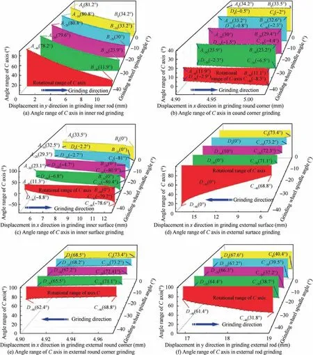
Fig. 3 Variation of rotation angle of C axis turntable at different grinding positions with tilting angle of grinding wheel spindle.
The grinding wheel inclination angle can not only affect the interference but also affect the distribution of the grinding points on the grinding wheel surface. The variation of minimum grinding position angle in different grinding sections with the grinding wheel spindle inclination angle is described in Fig.4.With the increase of the grinding wheel spindle inclination angle,all grinding position angles have shown an increasing trend. When grinding the external surface and external round corner,the curves of the grinding position angle changing with the spindle inclination angle overlap each other. Relative to the grinding of the external surface of the component,the influence of the inclination angle on the grinding sections of the inner surface is relatively significant.In the case of internal corner grinding, the increase of inclination angle helps to reduce the coincident length of the grinding line on the ballend grinding wheel surface, which is beneficial to obtain uniform grinding wheel wear, as shown in Fig. 4 (a) and (b).
After a comprehensive analysis, on the premise of increasing the grinding position angle as much as possible and avoiding interference, the inclination angle of the grinding wheel spindle is determined to be 40°. Then, the upper and lower limits of the C axis rotation angle can be calculated by the established model, and the results are described in Fig. 5,which means that the C axis must rotate within the limit in the subsequent grinding process. In the internal surface grinding, since the interference position transitions from the grinding wheel rod to the cylindrical part, there is a turning point,as shown in Fig. 5 (a).
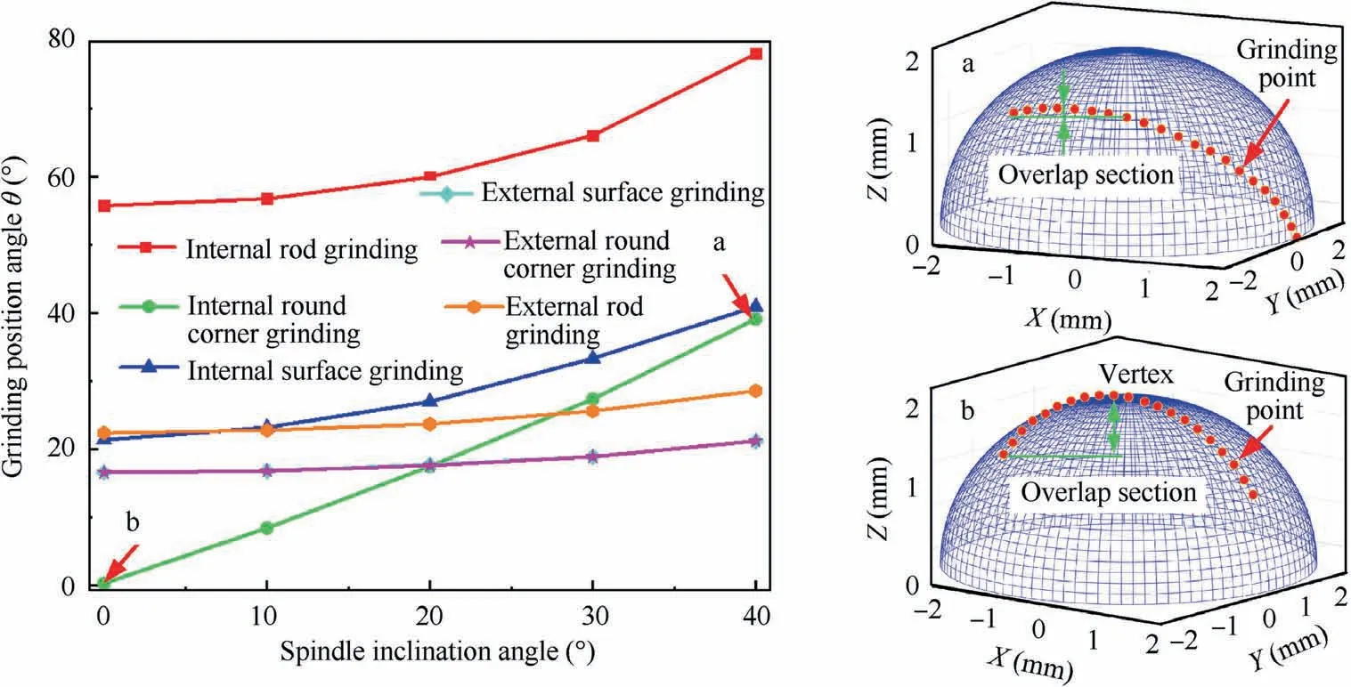
Fig. 4 Variation of grinding points distribution on ball-end grinding wheel surface with inclination angle of grinding wheel spindle.

Fig. 5 C-axis rotatable angle under inclination angle of grinding wheel spindle of 40°.
3. Trajectory planning of ball-end wheel for grinding the component
In the grinding process, grinding speed and grinding wheel wear will directly affect the machining quality. Therefore, in grinding trajectory planning,on the premise of avoiding interference,the grinding speed should be increased as much as possible, and the wear of the grinding wheel should be reduced.The rotation angle of the C axis will affect the grinding point distribution and the wear characteristics of the grinding wheel,which will affect the machining quality of the component.Since the grinding speed is proportional to the grinding position angle of the grinding point, the trajectory planning here is mainly about the design of the rotation angle of the C axis to optimize the grinding wheel wear and grinding position angle. In different grinding sections, the rotation angle of the C axis should be kept as constant as possible to avoid the impact of the C axis rotation accuracy and the eccentricity between the grinding wheel center and the C axis on the workpiece profile accuracy.During the grinding process of the thinwalled Ψ-shaped component, the ball-end grinding wheel needs to move along the profile line of the component to envelop the shape of the component.By considering the structural and grinding kinematic characteristics of the component,the component profile line can be divided into seven parts,namely A-G, as shown in Fig. 6.
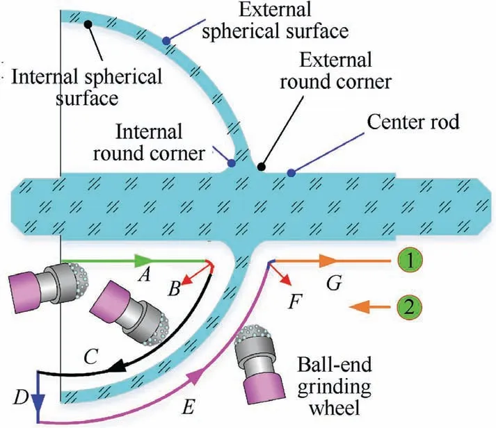
Fig. 6 Schematic diagram of trajectory planning for ultraprecision grinding process of complex component.
3.1.Effect of C turntable angular displacement on distribution of grinding points on the grinding wheel
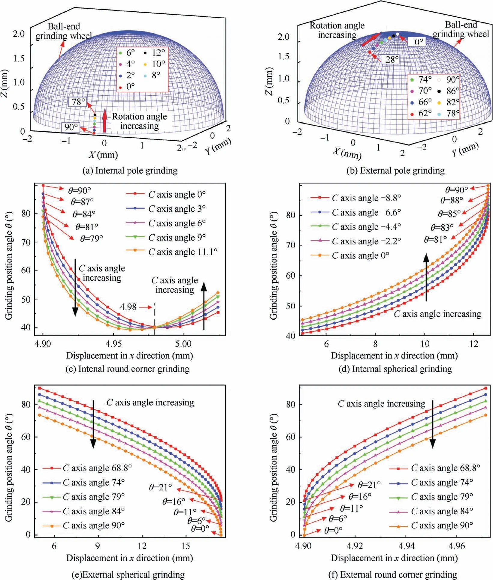
Fig. 7 Effect of C-axis rotation angle on distribution of grinding points on surface of ball-end grinding wheel.
Fig. 7 illustrates the effect of the C axis rotation angle on the grinding point distribution. For the center rod grinding,affected by the C axis rotatable angle, the grinding points are distributed near the position angle of 90° during the inner rod grinding;for the external rod grinding,the grinding points are located near the top of the ball end(see,Fig.7(a)and(b)).Therefore, the grinding quality of the inner rod will be significantly better than that of the external rod. With the C-axis rotation angle increasing, the grinding position angle decreases. When grinding the inner round corner and inner spheres,the grinding points are mainly distributed in the range of 40°-90°. And as the absolute value of the C axis rotation angle increases, the grinding position angle decreases, as shown in Fig.7(c)and(d).Fig.7(e)and(f)describe the grinding point distribution on the ball-end grinding wheel surface during the external round corner and spheres grinding. The distribution range of grinding points is from 0° to 86°, which is much larger than the distribution range of grinding points during inner surface grinding. As the C axis rotation angle increases, the grinding position angle also shows a trend of decrease.
3.2. Effect of C turntable angular displacement on wear of grinding wheel
The C axis rotation angle will affect the grinding point distribution on the ball-end grinding wheel,and further affect the wear volume of the grinding wheel at different grinding positions.Taking inner sphere grinding as an example,the grinding position angle of the grinding wheel is θ;the workpiece x-direction position is x; the grinding depth is Δa, and the grinding wheel radius wear is Δr,as shown in Fig.8.According to the definition of grinding ratio G,the following expression can be obtained:
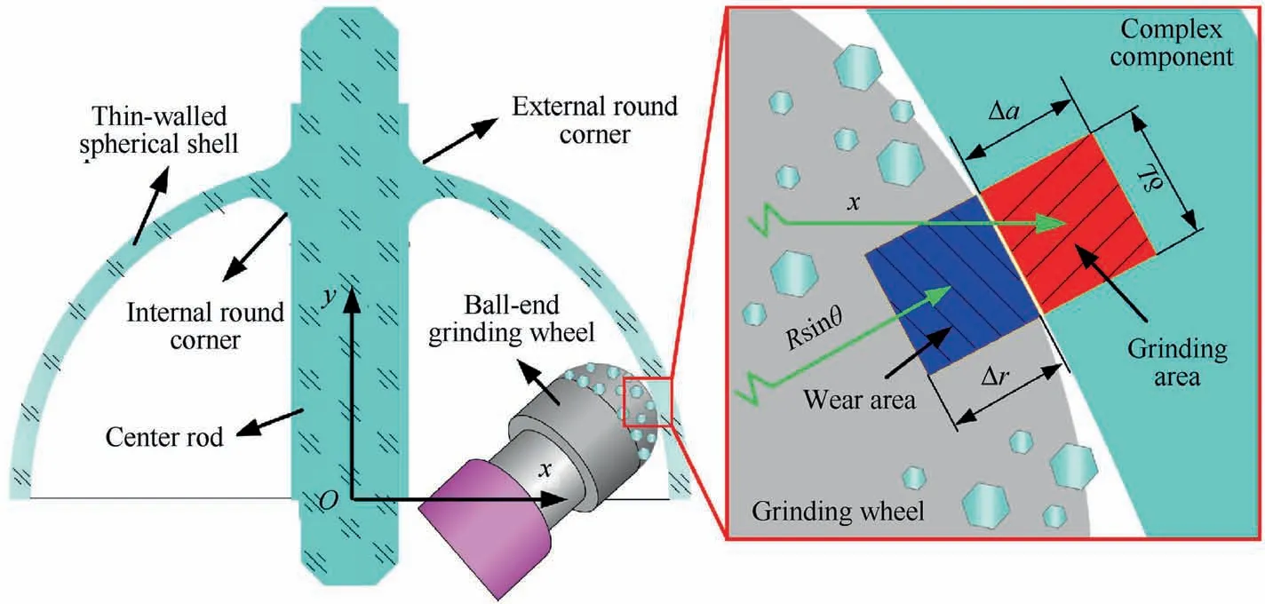
Fig. 8 Wear analysis at different positions of ball-end grinding wheel.

Since only one point of the grinding wheel participates in grinding the center rod and the material removal is small during round corner grinding, only the grinding wheel wear on the spheres grinding is analyzed, as shown in Fig. 9. For the inner sphere grinding, as the grinding position angle increases, the grinding wheel radius wear increases first, then decreases slightly and stabilizes (see Fig. 9 (a)). The wear also increases, as the absolute value of the C axis rotation angle increases. When grinding the external spherical surface, with the increase of the grinding position angle, the wear decreases rapidly and then slowly, as shown in Fig. 9 (b). Because the small angle position of the grinding wheel is used to grind the edge position of the external shell, the top of the ball-end grinding wheel is seriously worn. And the wear of the grinding wheel is obviously larger than that of the inner sphere grinding. As the C axis rotation angle increases, the wear decreases.
3.3. Planning and analysis of grinding trajectory for ball-end grinding wheel
For external sphere grinding, when the C axis rotation angle remains unchanged, the small angle position on the grinding wheel will participate in grinding. It will lead to severe wear of the grinding wheel and lower grinding speed,further affecting the profile accuracy and surface quality of the component.Therefore,the C axis rotation angle needs to be changed at an appropriate position to increase the grinding position angle,that is, the E section is divided into two parts, E1 and E2.According to the C axis rotatable angle, in order to make the grinding position angle greater than 45°, some positions that change the C axis angle are selected and compared in Fig. 10.
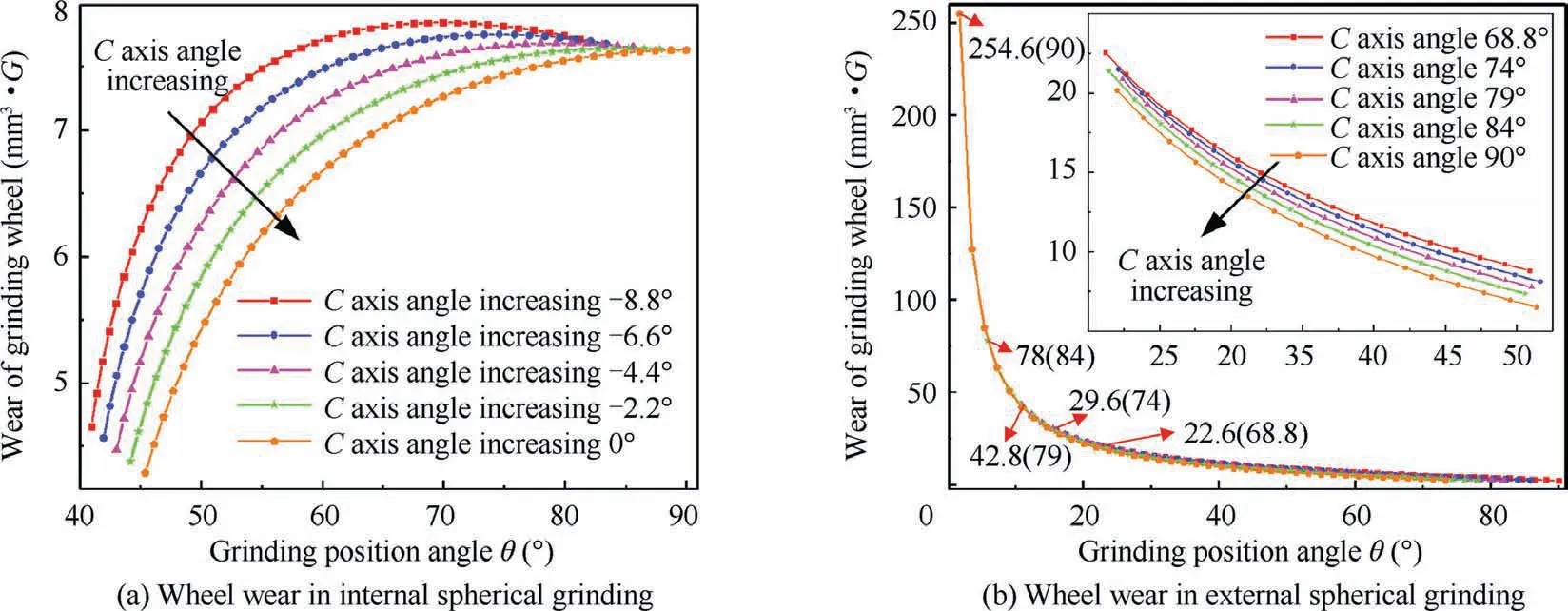
Fig. 9 Effect of C axis rotation angle on wear of ball-end grinding wheel.
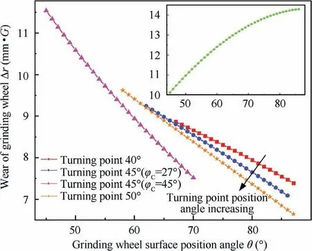
Fig.10 Influence of angular transformation position of external spherical surface of component.
By changing the C axis rotation angle when grinding the edge position of the spherical shell, the wear of the grinding wheel is effectively reduced. As the turning point angle increases, the wear of the grinding wheel radius decreases,and the arc length of the grinding wheel that take part in grinding increases.However,the increase of the turning point limits the rotatable angle range of the C axis and reduces the grinding position angle, which leads to the grinding speed decreasing.Therefore, the increase of the turning point will reduce the grinding wheel wear but also cause the grinding speed to decrease. Under the premise that the grinding position angle of all grinding points is greater than 45°, the turning point should be increased as much as possible,and the turning point angle is finally determined to be 50°. The selected C axis rotation angle has a dramatic effect on the grinding position angle and the grinding wheel wear.With the increase of C axis rotation angle,the grinding wheel wears severely,and the grinding trajectory moves toward the top of the ball-end grinding wheel, that is, the grinding position angle decreases. Finally,the angle of the turning point on the workpiece surface is determined to be 50°, and the C axis rotation angle in the E1 section is 27°, in the E2 section is 70°.
According to the analysis of the influence of the C axis rotation angle on the grinding position angle and grinding wheel wear, and the determination of the C axis rotatable range,the C axis rotation angles in different sections are determined and listed in Table 1.
With the determination of the grinding wheel spindle inclination angle and the C axis rotation angle in each grinding section, the distribution of the grinding points on the grinding wheel surface can be calculated, and the result is shown in Fig. 11. After segmented grinding of the external sphere surface, the position angles of most of grinding points during the grinding of the complex component are greater than 45°(see Fig.11(a)).Although the position angles of some grinding points are less than 45° when grinding the external round corner, the influence is limited because the corner is small. For grinding the inner round corner, the contact arc of the ballend grinding wheel is the longest, which is beneficial to improve the wear resistance of the grinding wheel. The grinding points are mainly distributed in the main grinding belt between 45° and 85° on the ball-end grinding wheel surface,as shown in Fig. 11 (b). Since the single grinding points forgrinding the inner and external rods are distributed outside the two ends of the main grinding belt, it will not affect the profile accuracy of the component.

Table 1 C-axis rotation angles in different grinding sections.
When the calculated grinding wheel wear caused by each grinding section is added up, the total grinding wheel wear is obtained, and the results are illustrated in Fig. 12. With the addition and withdrawal of each grinding section, the uneven wear appears on the grinding wheel surface, especially for the grinding wheel surface between 40° and 60°. Therefore,in the subsequent grinding wheel wear detection, grinding wheel dressing, and error compensation, sufficient attention needs to be paid to this area of the grinding wheel surface.When grinding the external rod,the wear of the grinding wheel is the most serious. Since the grinding point is not in the main grinding belt,it does not affect the grinding accuracy.But this will affect the grinding quality of the external rod of the component. However, limited by the C axis rotatable range, there is no good solution at present.
4. Analysis of relative cutting speed and maximum undeformed chip thickness of ball-end grinding
4.1. The relative speed between the component and ball-end grinding wheel
Grinding wheel speed is the main factor affecting the formation of ultra-smooth surfaces and the depth of subsurface damage.Based on the analysis of the grinding point distribution on the ball-end grinding wheel surface, the relative speed between the grinding wheel and workpiece is calculated, and the results are illustrated in Fig. 13. Since the diameter of the ball-end grinding wheel is small (only 3.8 mm), the grinding wheel speed is still low even if the rotation speed of the grinding wheel is as high as 70000 r/min. The grinding wheel speed is the largest when grinding the inner rod,which is about 14.5 m/s. For grinding inner round corner, inner and external spherical surfaces, the grinding wheel speed is main in the range from 10 m/s to 14.5 m/s,and when grinding only a small part of the corner,the grinding wheel speed is less than 10 m/s.As the outer section of the external round corner and external rod are ground,the grinding wheel speed will be as low as 4 m/s, which will have a certain impact on the grinding quality.
4.2.Analysis of maximum undeformed chip thickness of ball-end grinding the complex component
For ultra-precision grinding of hard and brittle materials,ductile domain grinding is an ideal material removal mode to improve the ground surface quality.The criterion for achieving ductile domain grinding is that the maximum undeformed chip thickness is smaller than the critical cut depth.According to previous studies,the critical cut depth can be calculated as:

where E is the elastic modulus, H is the hardness, and Kis the fracture toughness of fused silica. The detailed mechanical property parameter values of fused silica are listed in Table 2.
By bringing the corresponding mechanical parameters of fused silica into Eq. (32), it can be calculated that the theoretical critical cut depth of a single abrasive particle is 23 nm.Yao et al.adopted grinding research experiments to determine that the theoretical cut depth of fused silica is about 24 nm.Therefore, 24 nm is adopted as a criterion for the ductile domain grinding.
For studying the grinding characteristics of ball-end grinding wheels, it is necessary to calculate the maximum unde-
The commonly used maximum undeformed chip thickness of a single abrasive particle can be expressed as:

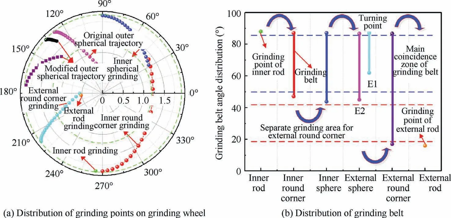
Fig.11 Distribution of grinding points on grinding wheel surface after trajectory planning.
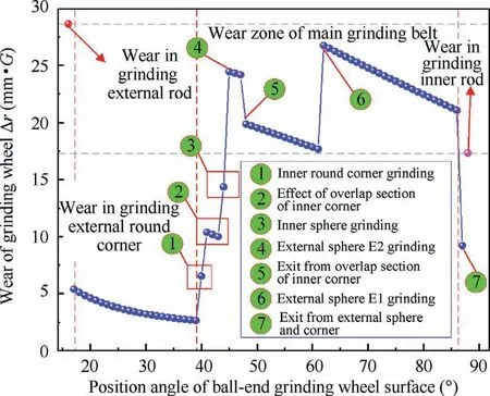
Fig. 12 Wear characteristics of ball-end grinding wheel after trajectory planning.
where C is the active abrasive grain number in per unit area;r formed chip thickness of a single abrasive particle at different grinding points. When the ball-end grinding wheel grinds the complex component, the material removal mechanism and calculation principle of the maximum undeformed chip thickness are illustrated in Fig.14.In the calculation process, when different positions of the workpiece are ground by the ball-end grinding wheel different positions, the workpiece and grinding wheel are simplified into a cylindrical workpiece and a cylindrical grinding wheel with the instantaneous radius,respectively.Based on the analysis of the actual grinding kinematics and the simplified interaction between the grinding wheel and the workpiece, it is found that the commonly used formula for calculating the maximum undeformed chip thickness is applicable to this grinding process.is the chip width-to-thickness ratio(r=10 is adopted);vand vare the workpiece speed and grinding wheel speed, respectively;ais the grinding depth;and drepresents the equivalent diameter of the grinding wheel. The calculation expression of C can be obtained through the geometric relationship as:

where χ is the effective abrasive grain percentage(1/3 here);dis the spherical diameter of the abrasive grain; ν is the volume fraction of the grinding wheel,which is 0.375.When the grinding conditions are as follows: the grinding depth is 1 μm, the grinding wheel speed is 71000 r/min, and the workpiece speed is 30 r/min,the calculation result of the maximum undeformed chip thickness for grinding of the complex component with the ball-end grinding wheel is shown in Fig. 15.
As the abrasive particle diameter increases, the maximum undeformed chip thickness increases. For inner round corner,inner and external spherical surface grinding, the maximum undeformed chip thickness increases as the displacement in the X direction increases, but the increasing trend is different.For the external round corner,the maximum undeformed chip thickness shows an opposite trend with the change in xdirection displacement. The grinding state of the inner rod is the best (see Fig. 15 (a)). Even if the abrasive particle size is 5 μm, the maximum undeformed chip thickness is less than the critical cut depth. Followed by the inner round corner and spherical surface, when the abrasive particle diameter is about 3 μm, the maximum undeformed chip thickness at all grinding points is less than the critical cut depth, as shown in Fig. 15 (b) and (c). Then the external spherical surface and round corner, when the abrasive particle size is 3 μm,the maximum undeformed chip thickness of most grinding points is less than the critical cut depth (see Fig. 15 (d) and(e)). The external rod has the worst grinding condition. For 3 μm abrasive particle, the maximum undeformed chip thickness is still greater than the critical cut depth. The small size abrasive particle will cause the wheel to wear faster and further affect the profile accuracy of the component. By comprehensively considering, the finally determined abrasive particle diameter is 3 μm.
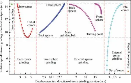
Fig. 13 Variation of relative speed between grinding wheel and workpiece.

Table 2 Mechanical property parameter values of fused silica.
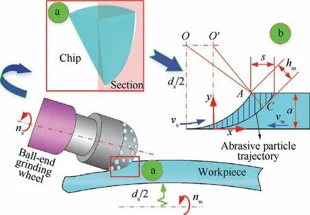
Fig.14 Theoretical analysis of maximum chip thickness for ballend wheel grinding spherical part.
For further studying the influence of grinding parameters on the maximum undeformed chip thickness of ball-end wheel grinding, it is necessary to study the sensitivity coefficient of each grinding parameter. Sobol’s method is adopted to investigate the first-order sensitivity coefficient of the influence of abrasive diameter (d), volume fraction (ν), grinding wheel speed (v), grinding wheel diameter (d), workpiece speed(v), workpiece diameter (d), and cutting depth (a) on the maximum undeformed chip thickness. The results are described in Fig. 16.
The influence of abrasive diameter on the maximum undeformed chip thickness is the largest,which is much larger than the other parameters, followed by the grinding wheel and workpiece speed. The smallest impact is the wheel diameter.Therefore, in the process of grinding complex components with ball-end grinding wheels, fine-grain grinding wheels can be adopted to improve the grinding surface quality.
5. Experiments
5.1. Experimental procedures
The grinding of the Ψ-shaped component with the small ballend grinding wheel is conducted on the self-developed ultraprecision grinding machineto verify the effectiveness of the proposed method. The machine has two stations for grinding and grinding wheel dressing, which can on-machine dress the ball-end grinding wheel during ultra-precision grinding, as shown in Fig. 17. Four-axis linkage can be realized by three linear axes (X, Y, Z) with a positioning accuracy of 0.5 μm and one rotation axis (C). The grinding wheel high-speed motorized spindle is inclined relative to the horizontal plane,of which the maximum rotation speed is 80000 r/min. The detailed parameters in the grinding experiments are listed in Table 3.
When the grinding wheel is installed on the grinding wheel spindle, the on-machine electric discharge dressing is performed on the ball-end diamond grinding wheel to improve the profile accuracy of the grinding wheel and reduce the eccentricity caused by the installation.For ultra-precision grinding of hard and brittle material fused silica, the wear of the ball-end grinding wheel is inevitable. Therefore, onmachine dressing of the ball-end grinding wheel in the ultra-precision grinding process can suppress the influence of grinding wheel wear. After grinding, a contact probe profilometer (PGI 1240, Talysurf®) is adopted to measure the profile accuracy and the surface roughness of the ground component. A three-dimensional optical microscope (HVX100,Keyence®) is used to observe the surface topography of the component.
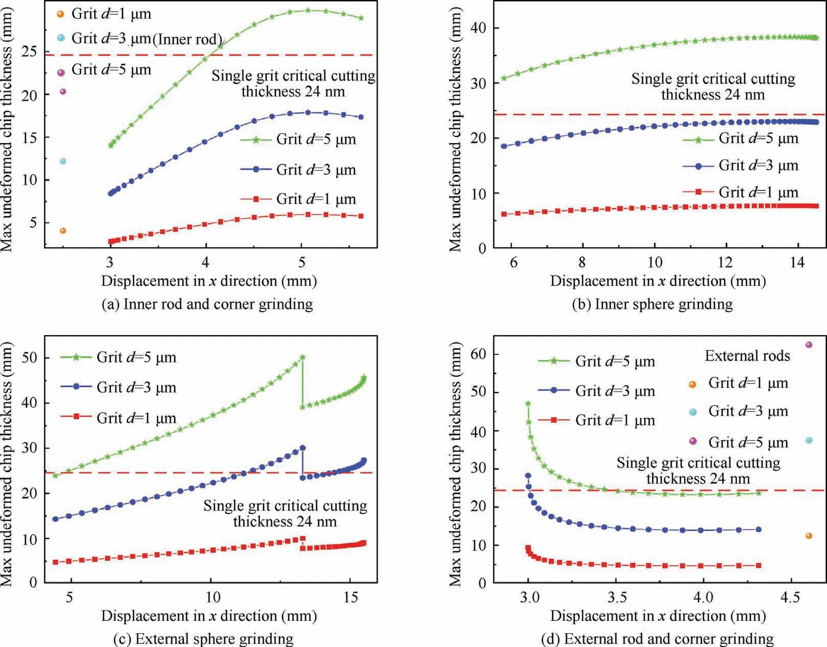
Fig. 15 Variation of max chip thickness of ball-end wheel grinding spherical part against grinding position.
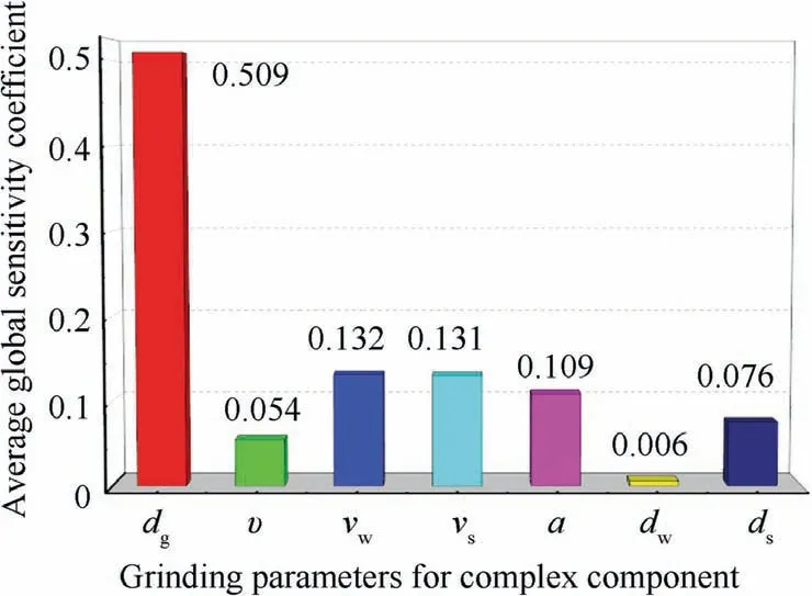
Fig. 16 Sensitivity analysis of grinding parameters for ball-end wheel grinding on the maximum chip thickness.
5.2. Experimental result and discussion
After the complex thin-walled component ground by the small ball-end grinding wheel,the experimental results are measured and compared in Fig.18.The complex component after grinding does not show any damage,indicating that there is no glo-bal interference in the ultra-precision grinding process. When local interference occurs, it will seriously affect the profile accuracy of the component. The profile accuracy (PV) of the ground complex component shown in Fig. 18 (c) is improved from 3.427 μm before ultra-precision grinding to 0.399 μm,which shows that there is no local interference to some extent.Therefore,it can be concluded that there is no interference during the grinding of the complex components with a small ballend grinding wheel, which further shows that the established mathematical model for interference analysis and the trajectory planning method are effective. Since the shape of the grinding wheel will change when it is severely worn,it will have a serious impact on the grinding profile accuracy. The experimentally measured profile accuracy results also indicate that the impact of the grinding wheel wear on the grinding process after trajectory planning is small.The surface morphology and surface roughness of the component after ultra-precision grinding can directly reflect the actual material removal mode in the grinding process. Hence, surface morphology and surface roughness are adopted to investigate the material removal mode in the complex component grinding with the small ballend grinding wheel. Before ultra-precision grinding, the component surface is covered with pits formed by brittle fracture(see Fig. 18 (a)), that is, the material removal mode during the grinding process is mainly brittle fracture. After ultraprecision grinding, the surface topography of the component is dominated by ductile stripes,with occasional brittle fracture pits, as shown in Fig. 18 (b), which shows that the material removal process is in the ductile domain grinding.The surface roughness of the component before and after ultra-precision grinding is 565 nm and 40.2 nm, respectively. These results can indicate the feasibility of the analysis method of the grinding characteristics of the ball-end grinding wheel in parallel grinding complex components and the effectiveness of the analysis results (especially for the maximum undeformed chip thickness).
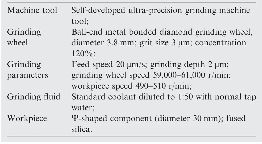
Table 3 Detailed parameters in grinding experiments.
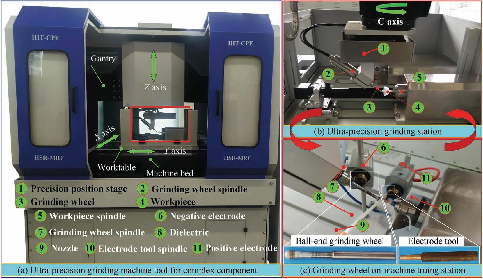
Fig. 17 Ultra-precision grinding machine for processing complex component.
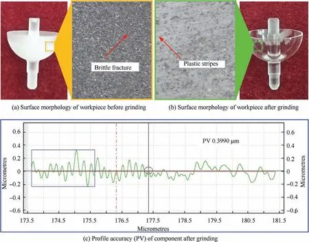
Fig. 18 Results of ultra-precision grinding of complex structural component.
6. Conclusions
This paper focuses on investigating the grinding of the thinwalled Ψ-shaped complex component with a small ball-end diamond grinding wheel.Based on the screw theory and grinding kinematic analysis, a mathematical model is established to study the interference and the grinding characteristics of the ball-end grinding wheel.
(1) With the grinding wheel spindle inclination angle increasing, the C axis rotatable range decreases, but the grinding point position angle on the grinding wheel increases. As the C axis rotation angle increases, the grinding position angle decreases, and the grinding wheel radius wear decreases.
(2) According to the trajectory planning criteria for increasing grinding speed as much as possible under the premise of avoiding interference, the grinding trajectory is planned. Then the position angle of most grinding points is greater than 45°,and the grinding speed of each grinding point is mainly between 10 m/s and 14.5 m/s.
(3) The sensitivity analysis of the grinding parameters indicates that the most significant effect is the abrasive particle size, followed by the workpiece and grinding wheel speed,and the smallest effect is the workpiece diameter.When the abrasive particle diameter is selected to be 3 μm, the maximum undeformed chip thickness at almost all grinding points is less than the critical cut depth of fused silica.
(4) Finally, in the verification experiments, the Ψ-shaped component can be ground by the ball-end grinding wheel without any interference, and the surface roughness and profile accuracy of the component can be improved from 556 nm and 3.427 μm to 40.2 nm and 0.399 μm,respectively.These results indicate the mathematic model can guide for analyzing the interference and grinding characteristics in thin-walled complex component grinding to improve its processing quality.
Declaration of Competing Interest
The authors declare that they have no known competing financial interests or personal relationships that could have appeared to influence the work reported in this paper.
Acknowledgement
This work was supported by the National Key Research and Development Program of China (No. 2018YFB 1107600).
 CHINESE JOURNAL OF AERONAUTICS2021年4期
- CHINESE JOURNAL OF AERONAUTICS的其它文章
- Time delay compensation in lateral-directional flight control systems at high angles of attack
- Dual stability enhancement mechanisms of axial-slot casing treatment in a high-speed mixed-flow compressor with various tip clearances
- Development cost prediction of general aviation aircraft using combined estimation technique
- Improvement on shaped-hole film cooling effectiveness by integrating upstream sand-dune-shaped ramps
- Modeling and parameter identification of linear time-varying systems based on adaptive chirplet transform under random excitation
- An experimental method to obtain the hard alpha anomaly distribution for titanium alloy aeroengine disks
