Neck-spinning quality analysis and optimization of process parameters for plunger components:Simulation and experimental study
Yng WANG, Honghu SU,*, Ning QIAN, Kui LIU, Jino DAI,Zhengi ZHAO, Wenfeng DING
a College of Mechanical and Electrical Engineering, Nanjing University of Aeronautics and Astronautics, Nanjing 210016, China
b Singapore Institute of Manufacturing Technology,73 Nanyang Drive, Singapore 637662, Singapore
c School of Mechatronic Engineering, China University of Mining and Technology, Xuzhou 221116, China
KEYWORDS Fuzzy method;Neck-spinning quality;Plunger component;Range analysis;Simulation
Abstract The plunger component is a key part of the plunger pump in the aircraft hydraulic system.Neck-spinning process is commonly used to fabricate plunger components,of which the quality of the spinning process significantly affects the performance of plunger pumps. One of the bottlenecks faced by the industry in the spinning process is to choose a suitable neck-spinning process so as to ensure the quality of plunger components.It is necessary to propose a reliable method to optimize the process parameters which affect the neck-spinning quality of plunger components.In this study, a calculable finite element analysis (FEA) model is established to simulate the threeroller neck-spinning process of the plunger component,which includes six typical slipper structures,two roller structures,and two spinning parameters.The FEA model is then validated by comparing the simulated spinning forces with the corresponding experimental results.The influence of the process conditions on the neck-spinning quality is investigated. And the orthogonal simulation results are analyzed by a combination of range method and fuzzy mathematical analysis method to recommend a reasonable slipper structure,roller structure and neck-spinning parameters.This study provides a promising method to improve the manufacturing quality of the typical plunger components.©2020 Chinese Society of Aeronautics and Astronautics.Production and hosting by Elsevier Ltd.This is an open access article under the CC BY-NC-ND license(http://creativecommons.org/licenses/by-nc-nd/4.0/).
1. Introduction
The aircraft plunger pump is a key power component in an aircraft hydraulic system due to its excellent properties, such as compact structure, small rotational inertia, large flow and easy to control variables, etc.The plunger component is a critical part of the plunger pump since the reciprocating movements of a plunger in the chamber can change the volume to absorb and drain oil,and its processing quality will directly affect the volumetric and mechanical efficiencies, reliability,durability and lifetime of the plunger pump.At present,the popular necking-in method of the plunger components is the neck-spinning process which has the advantages such as excellent stability, high efficiency, low loading, cost saving and high precision.However, the spinning process of the plunger component is a complex plastic deformation process,the forming mechanism is complex, the spinning process and spinning precision are affected by many factors and technological conditions, and consequently the spinning process of the plunger component often has exposed quality problems of large variance and instability.Therefore,it is urgent to develop scientific and effective methods to optimize the size of base structure and neck-spinning process,so as to improve the qualified rate of the products.
At present, the research on the reliability and optimization of the spinning process has been paid many attentions by many scholars, but there is still a blank in the formulation and optimization of spinning process for the plunger components.Whereas many early scholars conducted researches on the mechanism of metal spinning and the optimization of spinning process parameters for axisymmetric and non-axisymmetric parts, which is still of great help in the development of this study. Previous numerical analysis and experimental methods were the main means of studying the spinning forming mechanism and flow control, which primarily involves the spinning force, torque and surface damage.In recent years, more scholars get interested in the finite element method (FEM),because it can provide detailed solutions to revealing the forming characteristicsand defecting forming mechanisms.Wang and Longused the method of FE analysis and experiment to investigate the wrinkling failure of cylindrical cup during conventional spinning, and the results show that the severity of wrinkles increased with the increase of roller feed ratio. Huang et al.carried out the experiments and simulations the neck-spinning process of the circular pipe at elevated temperature by FEM. Zhang et al.proposed an optimized neck-spinning technique to improve the inner surface quality of cylindrical workpieces by reversing the material flow direction.Luo,et al.presented a kind of compound spinning process which is composed of a counter-roller spinning, multineck spinning and hot spinning by FE method. Takahashi,et al.used experiments and three-dimensional FE simulations to study the effect of neck length on tube cracking during the spinning process. Guo, et al.studied the spinning force law in counter-roller spinning,and analyzed the effects of thinning rate, feed speed and roller angle on spinning, and determined reasonable process parameters. The FE model was established by Zeng, et al.was used to study the typical deformation characteristics and forming defects in the flow forming process of tubular parts with crossed internal ribs.Li and Shuestablished the mathematical model of the involute curve roller trajectory and the spinning FE model, and used forming clearance compensation in the attachingmandrel process. It is proposed that forming clearance compensation can greatly shorten the forming time and the crack location is analyzed. Ye, et al.conducted a simulation study on the spinning process of non-axisymmetric inclined flange cylinder, the effect of the axial roller feed along the wall on the thickness distribution and stress-strain during the forming process was analyzed, and deduced the roller path formula.
However,in the above literatures,the research on the optimization of spinning parameters mainly focused on the parts with mandrel which shares the same shape, after the spinning process, the mandrel is removed from the part, the main concern is also the spinning quality of the workpiece itself. While in the neck-spinning process of the plunger component, the plunger ball functions as a mandrel, and after the process the plunger ball needs to be kept inside the slipper to work with the slipper to form the final product.Moreover,it raises high precision requirements about the matching between the slipper and the plunger in the plunger component, these include a sufficient pulling-out force and plunger swing angle and a suitable axial clearance.However,due to the lack of scientific and efficient methods to develop a reasonable workpiece structure and neck-spinning process to improve the spinning quality of the plunger component, so it is necessary to carry out the related research.
The present study is devoted a dependable and sophisticated FEA model of the plunger component neck-spinning process by the commercial software ABAQUS 6.14/Explicit,and the correctness of the FE model was verified by spinning experiments. Besides, the FE model is used to analyze the neck-spinning process of different roller structure(front angle,diameter),slipper structure and spinning parameters(feed rate,rotational speed), and the influence law of the processing conditions of the neck-spinning quality (axial clearance, pullingout force, swing angle) is analyzed. Finally, the orthogonal simulation results are analyzed by combining range method and fuzzy mathematical analysis method, the reasonable neck-spinning parameters and structure of the roller are presented.For an easy understanding of the optimization process of the neck-spinning process parameters, a research flowchart is first demonstrated in Fig. 1.
2. Development of FEA model
2.1. Introduction of neck-spinning process
The neck-spinning process of the plunger components, mainly includes a squeeze of the convexity of the slipper by the rollers,so that the convex continuously deforms and wraps the plunger.A schematic diagram of the necking process of the plunger component is demonstrated in Fig. 2. Firstly, the rear part of the slipper is fixed,and then the ball of plunger is inserted into the slipper, and the plunger is fixed through the tailstock. The three rollers are evenly distributed at 120° in the peripheral direction of the slipper and press the surface of the slipper.The spindle of the machine tool drives the slipper to rotate,the convex of the slipper deforms with the axial infeed of the rollers, during the neck-spinning process. When the rollers leave the slipper, the whole process completes.
2.2. FEA model
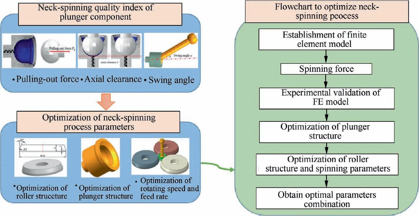
Fig. 1 A flowchart of neck-spinning process optimization of plunger component.
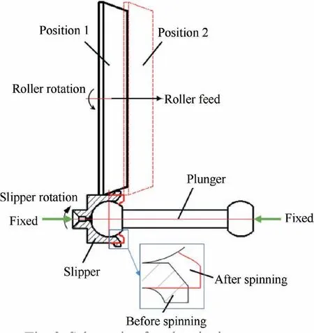
Fig. 2 Schematic of neck-spinning process.
In this study, the ABAQUS 6.14/Explicit module is used to establish the Elasto-plastic FEA model of the plunger component under the three rollers distribution modes in the neckspinning process, as shown in Fig. 3(a). The simulation contains slipper, plunger and three rollers. The slipper is made of AISI 5135 steel elastoplastic material with a density of 8000 kg/m,the mechanical properties of this material are tabulated in Table 1.In our previous study,the stress-strain relationship in the plastic deformation stage of the slipper material has been experimentally measured under room temperature by using a tensile testing machine,so the stress-strain curve are not repeated in this study.
As shown in Fig.3(a),the boundary conditions include the movement and constraints of the plunger, slipper, and rollers.According to the production experience, the slipper only retains the degree of freedom (DOF) of the rotation around its own axis. Because the plunger is affected by the friction on the inner surface of the slipper, the plunger only retains the DOF of rotation around its own axis.The rollers can move along the Y-axis direction and rotate around its central axis freely, while the DOF in other directions is fixed. According to the Coulomb friction model, the friction coefficient is 0.15when no lubrication is used between the rollers and slipper, slipper and plunger. The roller can be rotated by the slipper due to the friction.
For the spatial discretization of the FEA models, the slipper of the plunger component is divided with 3D 8-node brick elements with reduced integration (C3D8R), the total mesh number reached 36652,as shown in Fig.3(b).In order to save calculation time, local mesh refinement is carried out in the contact area(convex shape)between the roller and the slipper,and relatively coarse mesh is used for other areas of the slipper.The Arbitrary Lagrangian Eulerian (ALE) adaptive meshing technique is adopted to automatically regenerate the finiteelement mesh and control element distortion at each time increment during neck-spinning process of the plunger component. The slipper is considered as a deformable body and the plunger and rollers were represented by analytical rigid bodies.The penalty contact method was adopted to simulate the contact between the material and tools, and the Coulomb friction law was selected to model the sliding behavior between them.
2.3. Neck-spinning quality evaluation index measurement
The quality evaluation indexes of the plunger component are axial clearance C, pulling-out force P and the swing angle α of the plunger. The schematic diagram of each quality evaluation indexes is shown in Fig. 4. As shown in Fig. 4(a), the pulling-out force is the minimum force P required for the plunger to pulling out from the slipper after the slipper is spun,it is to evaluate the bonding strength standard between plunger and slipper.As shown in Fig.4(b),the axial clearance C refers to the maximum axial displacement of the plunger in the slipper after the slipper is spun, it affects the vibration and stability of the plunger component in use.As shown in Fig.4(c),the swing angle α is the maximum angle that the plunger can swing in the slipper after the slipper is spun,it directly affects the flexibility of the oil pump.These three indicators are all influenced by the forming quality of plunger component. However, current quality testing methods mainly rely on high cost and inefficient manual measurement. Therefore, it is necessary to optimize the spinning process and provide a reliable combination of process parameters to improve the quality of the neck-spinning process, the FE method shows a greater advantage from the perspective of economy and time.
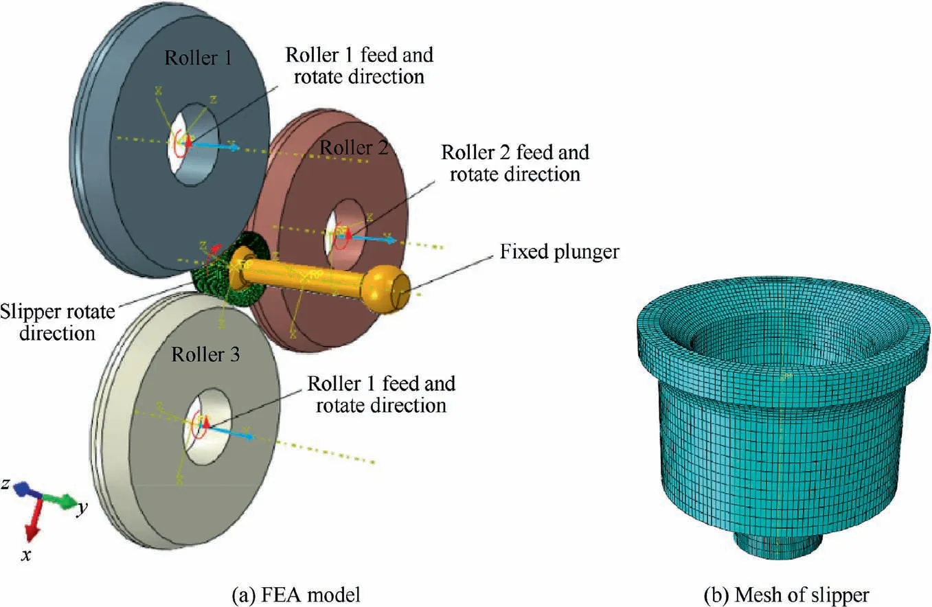
Fig. 3 FEA model of neck-spinning process for plunger component.
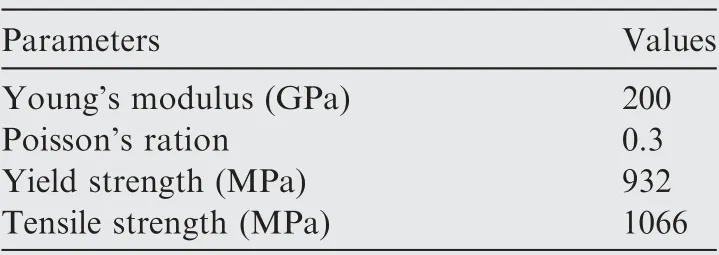
Table 1 Mechanical properties of AISI5135 steel.32
3. Experimental design
The neck-spinning experiments were carried out on a high precision CNC lathe(SK-50P),and no coolant is used during the experiments. Axial spinning force (z axis direction) was measured by the dynamometer(Kistler 9272)and charge amplifiers(Kistler 5070A). The data from the dynamometer were acquired and treated using DynoWare on a computer, and the low pass cutoff frequency is 30 Hz. The principle of the axial spinning force acquisition system is shown in Fig. 5(a),the experimental setup is displayed in Fig. 5(b). In order to successfully complete the neck-spinning experiments on the lathe, a set of special fixtures designed with simple structure and convenient installation are used for the installation of the three rollers and the Kistler 9272 dynamometer, as shown in Fig.5(b).The slipper is located in the center of scaffolds,the slipper and the plunger are mounted with the tailstock of the lathe and the micro clamp respectively. The three rollers are uniformly installed on the side of scaffolds, and the scaffolds are fixed on the dynamometer.The dynamometer is connected with the feeding system of the lathe,so as to drive the rollers to complete the axial feed motion (z axis direction), and the rollers will rotate due to the action of friction. Until the rollers completely leaves the surface of the slipper, and the whole neck-spinning process is completed.
The single factor experiment method was used in the present spinning experiments. The feed rate f of the rollers was changed to analyze the influence on the axial spinning force Fand analyze the reliability of the finite element model.Fig. 6 shows the schematic diagram of slipper and roller, as shown in Fig. 6(a), where lis the straight edge length of slipper and Dis the slipper diameter and Ris the slipper circular radius. As shown in Fig. 6(b), where θ is the front angle of roller and Dis the roller diameter.Table 2 lists the processing parameters applied in experiments.

Fig. 4 A schematic diagram of quality evaluation indexes for plunger component neck-spinning.
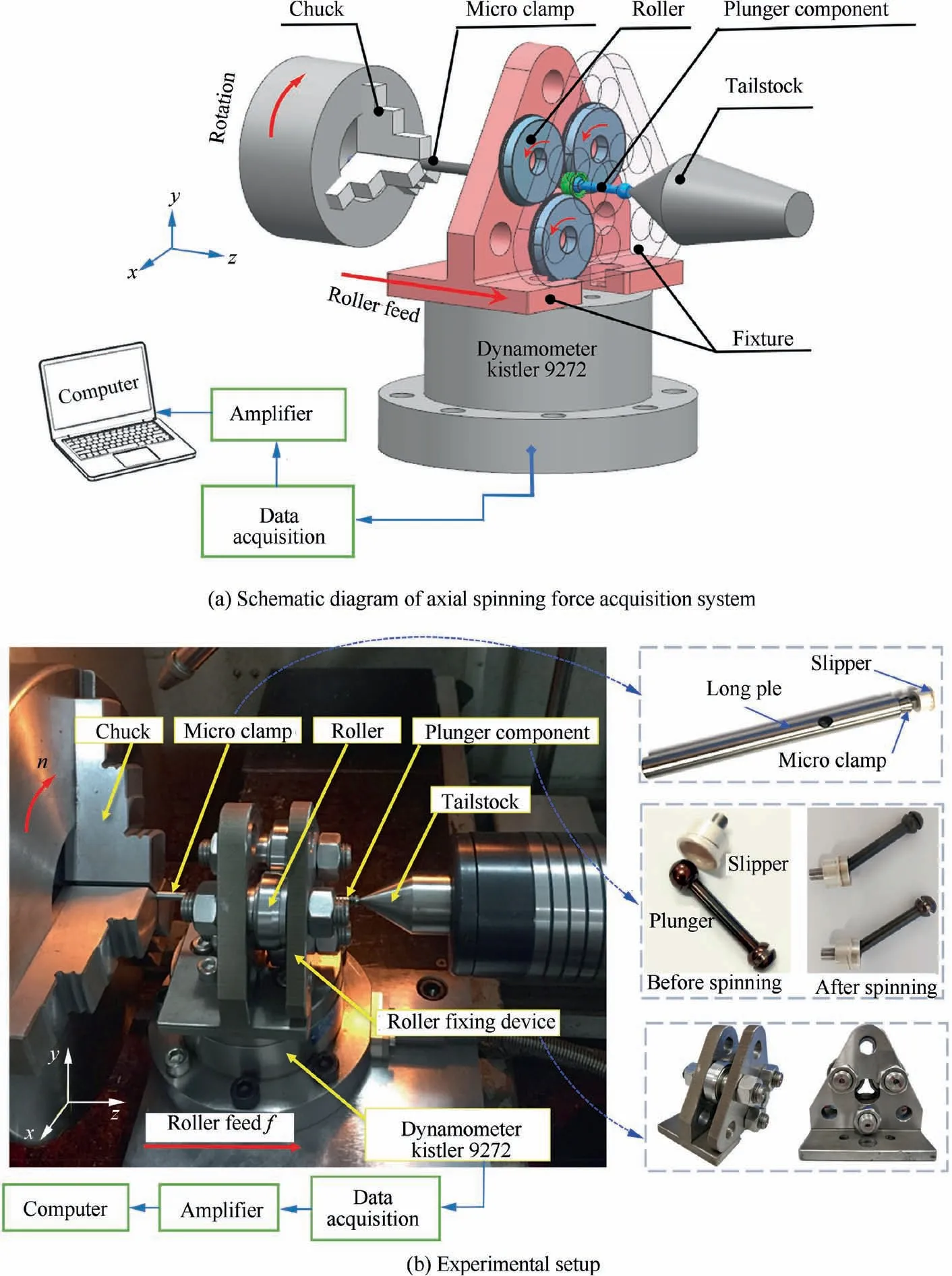
Fig. 5 Schematic diagram and experimental setup of axial spinning force acquisition system.
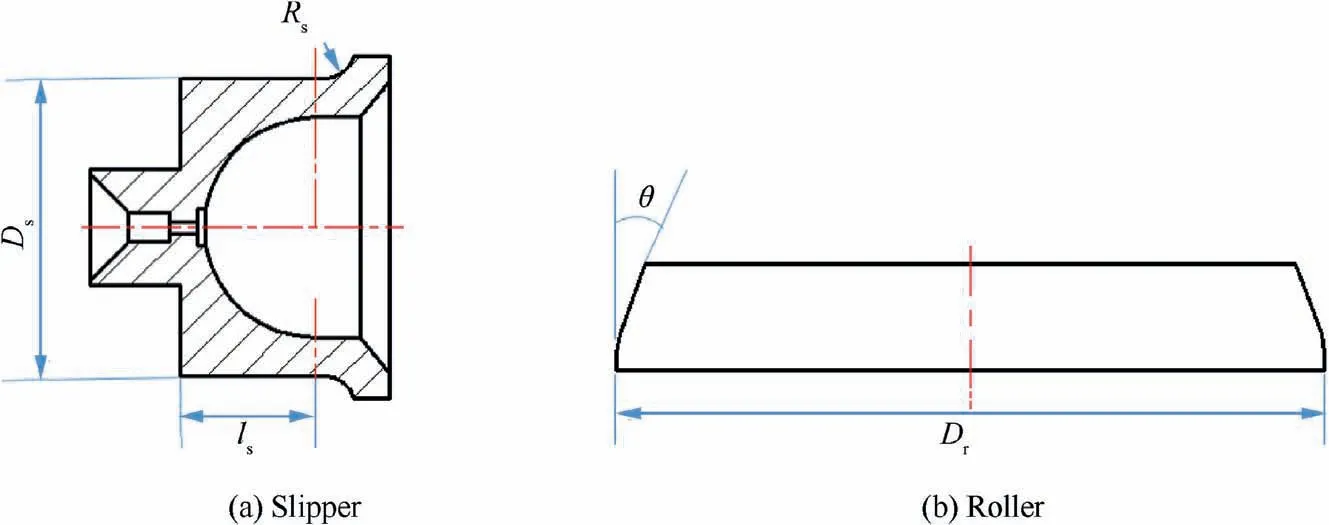
Fig. 6 Schematic diagram of slipper and roller structure.
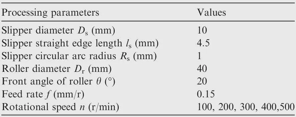
Table 2 Parameters of neck-spinning experiments.
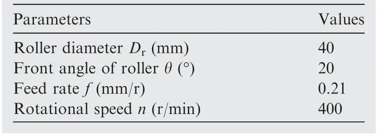
Table 3 Simulation parameters for structural optimization of slipper.

Table 4 Simulation parameters for optimization of rollers structure and spinning parameters.
Table 3 shows the simulation parameters selected for the optimization of slipper structure,and Table 4 shows the simulation parameters selected for the optimization of roller structure and spinning parameters.
4. Results and discussion
4.1. The simulation analysis
The simulation analysis is conducted to evaluate the equivalent plastic strain (PEEQ) and stress distribution of the slipper under the processing parameters of n=100 r/min and f=0.15 mm/r. The PEEQ and stress distribution of neckspinning process at each completion ratio r of the slipper are shown in Figs. 7 and 8. The rollers and plunger are hidden.Figs.7(a) and 8(a)show the initial state of the slipper without contact with the rollers. As shown in Fig. 7(b)-(e), the mises stress of the slipper acts in the spinning process. With the spinning process, the maximum stress of slipper almost remains unchanged, and the stress is concentrated in the contact area between slipper and rollers. Fig. 8(b)-(e) shows the PEEQ distribution of slipper at each deformation stage.It can be found that the maximum strain value is almost the same, the position of the maximum strain appears in the contact position of the rollers and the slipper. It can be seen from the strain distribution in different time periods that the spinning process is stable and reliable.
Fig. 9 shows the distribution of the tangential, axial and radial stress and strain of the formed slipper. These analyses can explain the development and occurrence of deformation in the neck-spinning process.It can be seen from Fig.9(a)that the outer surface of the slipper is subject to tensile stress in the x-direction, while in the inner blue area, the stress is negative,indicating that it is subject to compressive stress,which is helpful to compress the plunger.Fig.9(b)shows that the tangential strain occurs mainly at the convex of the slipper, is the tensile strain, and the maximum tangential strain value is 0.43.
It can be seen from Fig.9(c)that the blue area on the upper part of the ball socket inside the slipper is mainly subject to the compressive stress in the y-direction, while the convex is mainly subject to the tensile stress in the y-direction caused by the extrusion of the rollers. As shown in Fig.9(d),the convex of the slipper is mainly affected by tensile strain in the ydirection.The axial strain of the outer layer is greater than that of the inner layer,and the maximum axial strain value is 0.918.
Fig. 9(e) shows that the blue area inside the slipper is subjected to radial compressive stress, while Fig. 9(d) shows that the strain value at the outer convex of the slipper is negative,So the convex of the slipper is under radial compressive stress,and the maximum radial strain value is 0.476.
In addition, by comparing the strain values of the three directions,it is found that the axial strain value is almost twice as much as the tangential and radial strain value, so the axial stretch of the slipper convex plays a major role in the neckspinning process.
4.2. Validation of the FE model
Fig. 10 compares the simulated and experimental axial spinning forces at different rotational speeds.The rotational speeds are selected within the range of 100-500 r/min, the constant interval is 100 r/min. The feed rate is constant at 0.15 mm/r.From Fig. 10(a)-(e), the simulated and experimental axial spinning forces share a resemblance, but with different peak values. The change in the maximum axial spinning force with respect to the rotational speed is plotted in Fig.10(f).By comparing the maximum axial spinning force Fmeasured by the simulations and experiments,it is found that the maximum error is smaller than 15%, which is acceptable. Therefore, the accuracy of the FE model is verified. In addition, as shown in Fig.11,the experimental and simulated axial elongation L and diameter of the convex d of the formed slipper are respectively compared. It can be seen from Fig. 11 that the simulation results are very similar to the experimental results, and the maximum error is also smaller than 15%. Therefore, based on the comparison between the above results of the experiment and simulation, the accuracy of the FE model is verified.
4.3. Structural optimization of the slipper

Fig. 7 Stress distribution at various simulation stages.

Fig. 8 Strain distribution at various simulation stages.
Due to the complicated structure of the slipper itself,there are many types of convex shape. The convex shape of the slipper has an important influence on the neck-spinning quality(axial clearance, pulling-out force and swing angle) after the neckspinning process. The main types of convex shape are shown in Fig.12(a)-(f),where Type a indicates that the convex shape is a combination of bevel edge and bevel edge.Type b indicates that the convex shape is a combination of bevel edge and arc.Type c indicates that the convex shape is a combination of bevel edge, straight edge and vertical edge. Type d indicates that the convex shape is a combination of arc and bevel edge.Type e indicates that the convex shape is a combination of arc and arc. Type f indicates that the convex shape is a combination of arc, straight edge and vertical edge. The simulation parameters of structural optimization of the slipper are shown in Table 3.
Fig.12 shows the different convex shapes of the slipper and corresponding simulation results. It can be found that the stress in the forming process of different slipper types is mainly concentrated in the contact area between the rollers and the slipper.In addition,different convex shapes will lead to different forming processes,when the completion ratio r of the neckspinning process reaches 75% and 100%, it can be found that the plunger sphere is not completely covered by slipper, indicating that the axial elongation of Type a and Type d is smaller than that of other types of slipper. It is further explained that the structure of different slipper convex has an important influence on the neck-spinning process,and the influence of the different convex shape of the slipper on the neck-spinning quality evaluation index of the plunger component will be analyzed below.
4.3.1. Comparison of the pulling-out forces in different convex shape types
In this study, a new analysis step was added to the FE model,that is,an axial pulling force Pwhich increases linearly in the axial direction is applied to the plunger. When the plunger is pulled out, the time t is recorded. The product of time t and axial pulling force Pcan be used to obtain the value of the minimum pulling-out force P of the plunger component. As shown in Fig.13,the method of obtaining the pulling-out force P is introduced by taking the spinning parameters of 400 r/min, 0.21 mm/r, the diameter of the roller of 40 mm and the front angle of 20°, type f as an example. The detailed method to obtain the pulling-put force P is to add a new analysis step to the FE model. That is, an axial pulling force P, which increases linearly in the axial direction is applied to the plunger, the axial loading rate is 2000 N/s. Fig. 13(a) shows the different pulling-out stages as the axial displacement of the plunger increases. Fig. 13(b) the black solid line shows the change of the contact force between the outer surface of the plunger and the inner surface of the slipper, while the red dashed line shows the axial displacement of the plunger.As shown in Fig. 13, when the time reaches t(2.844 s), the contact force between the plunger and the slipper reaches the peak value, and the plunger displacement increases suddenly,indicating that the plunger has been completely detached from the slipper. The loading rate 2000 N/s is multiplied by time t2.844 s to obtain the pulling-out force P is 5688 N.
Fig. 14 shows the results of pulling-out forces in the neckspinning simulation of each convex type. As can be seen from the Fig. 14, the pulling-out force is significantly higher when the arc of the convexity is replaced by the bevel edge.The reason is that when a bevel edge is used instead of an arc, the material of the inward contraction after the neck-spinning process will increase, which leads to the tighter packing of the plunger in the slipper. Therefore, the result of increasing the pulling-out force appears. Since the spinning quality of the plunger component is positively correlated with the pullingout force, the convex shape of different types of slipper is in the order of best to worst: Type c, Type b, Type a, Type f,Type e and Type d.
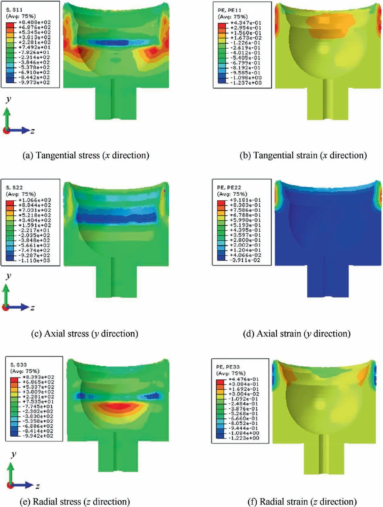
Fig. 9 Stress and strain distributions in three directions.
4.3.2. Comparison of the axial clearance in different convex shape types
As shown in Fig.15(a),the axial clearance can be obtained by setting a constant axial movement speed 1 mm/s is set for the plunger after the neck-spinning process,when the axial contact force Fdirection between the inner surface of the slipper and the outer surface of the plunger sphere is changed, the time of movement of the plunger is recorded. Fig. 15(b) shows the axial contact force Fand axial displacement of the plunger l versus the simulating time under the condition of f=0.21 mm/r, n=400 r/min, D=40 mm, α=20° and the convex shape of the slipper is Type f.When the simulating time reaches 0.12968 s, the magnitude of the axial contact force transits from negative into a positive value. That is, the plunger moves from the lower to the upper surface of the slipper.The axial movement speed 1 mm/s is multiplied by the time t of 0.12968 s to obtain the axial clearance is 0.12968 mm.
In order to avoid too large axial clearance of the plunger component resulting in vibration during operation, the axial clearance of the plunger component after a neck-spinning process should be kept as small as possible. However, if the axial clearance is 0, it will cause severe friction between the slipper and the plunger. Therefore, the axial clearance after the neck-spinning process should be larger than 0. Fig. 16 shows the axial clearance results obtained by neck-spinning FE simulation for each convex shape of the slippers. Among them,the axial clearance of Type a, b and c does not meet the requirement of greater than 0. Therefore, the remaining three types are in the order from best to worst according to the reason of smaller axial clearance. They are: Type e, Type f and Type d.
4.3.3. Comparison of the swing angle in different convex shape types
The approach to obtain the swing angle is to extract the slipper model after the neck-spinning simulation through the software ABAQUS,then to export the input file of the extracted model into the software Hypemesh, and export each surface into the software UG NX as an entity. Finally, the 2D solid model exported to UG NX software is exported to AutoCAD, and the swing angle can be obtained directly and conveniently.Fig. 17 shows a flowchart of swing angle measurement.
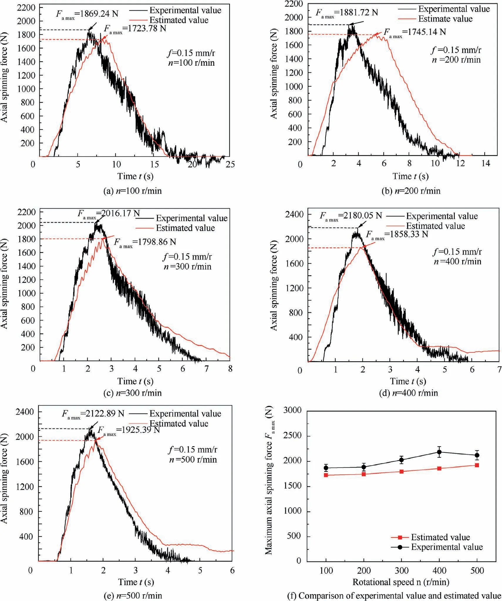
Fig. 10 Comparison of experimental and simulated axial spinning force at different rotational speeds.
The swing angle is one of the key parameters related to the normal operation of the plunger components in the oil pump.If the swing angle is too small, it is easy to cause the plunger stuck. Therefore, the scheme with a larger swing angle is preferred.The swing angle results in the neck-spinning simulation of each convex shape are shown in Fig.18,each convex type is in the order of good to bad: Type e, Type d, Type b, Type a,Type f and Type c.
Besides, it is also found from the results of the Fig. 18 that the swing angle obtained by using the arc at the convex shape is obviously larger than that obtained by using the bevel edge.This is because when the bevel edge is adopted at the convex shape, the material of the slipper is increased, which limits the rotation range of the plunger in the slipper, so the swing angle of the plunger will become smaller.
4.3.4. Optimization results of the slipper
Since the convex shape optimization of the slipper needs to consider multiple indexes, for the multi-index test, the evaluation of the experimental treatment scheme becomes complicated and difficult due to the incompatibility and contradiction among the indexes, the convex shape scheme of the slipper is optimized based on the fuzzy analysis method.According to the membership principle of fuzzy mathematics,the comprehensive evaluation method transforms qualitative evaluation into quantitative evaluation, that is, fuzzy mathematics makes an overall evaluation of things or objects restricted by various factors. It has the characteristics of clear results and strong systematicness, and can solve vague and hard-to-quantify problems well, so it is suitable for solving various non-deterministic problems.
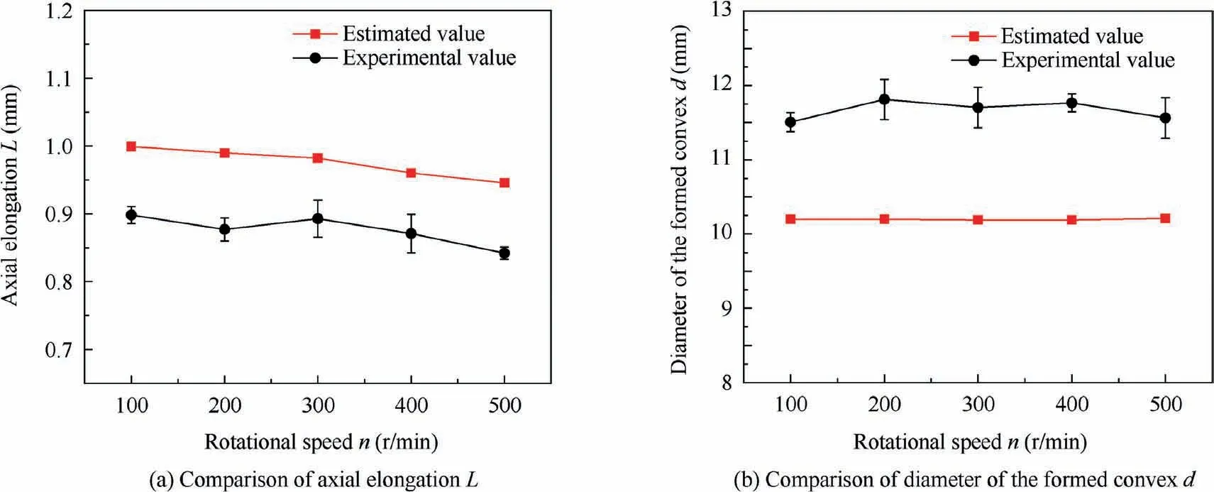
Fig. 11 Comparison of experimental and simulated geometry size of forming results of slipper.
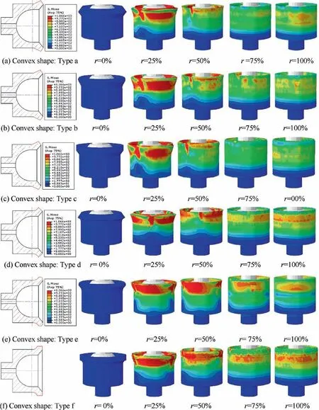
Fig. 12 Different structural types of slipper.
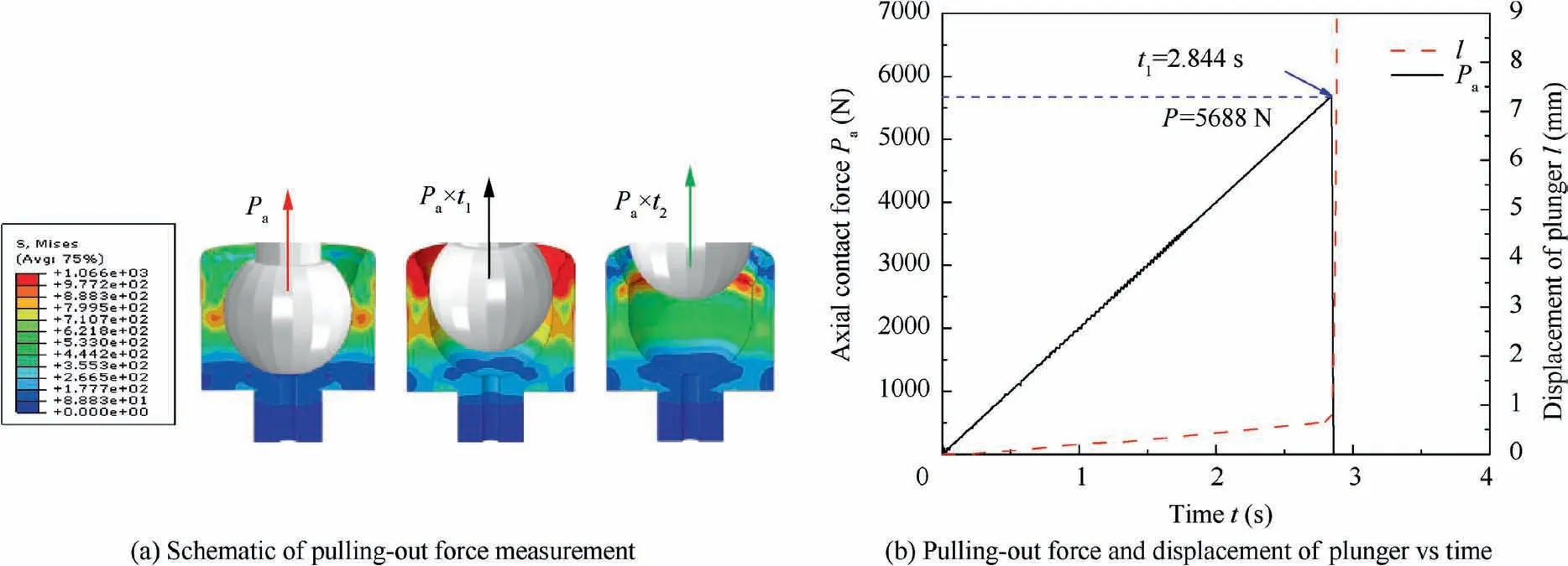
Fig. 13 Method of measuring pulling-out force.
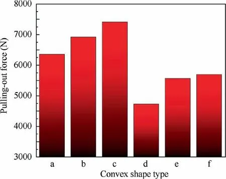
Fig. 14 Comparison of pulling-out forces in different convex shape types.
The above six types are respectively represented by X, X,X,X,Xand X,since Type a,Type b and Type c have been excluded, only the remaining three schemes need to be analyzed, denoted as X=[X, X, X]. The evaluation indexes mainly include pulling-out force P,axial clearance C and swing angle α,which are denoted as k,k,krespectively.The multiindex analysis matrix is denoted as k=[k, k, k]. Meanwhile, the No. i index in the No. j scheme is denoted as k,and the multi-index analysis matrix is obtained as shown in Eq. (1).

The first and third columns in the matrix respectively represent the values of pulling-out force, axial clearance and swing angle obtained by neck-spinning simulation of the three schemes, as shown in Table 5.
According to the above analysis, the optimization criteria of each evaluation index are different, that is, the smaller the axial clearance is, the better, while the larger the pulling-out force and the swing angle is,the better.It is difficult to get consistent evaluation results if we directly analyze these three indicators. In order to solve this problem, the reciprocal values of the pulling-out force and swing angle were used as the new evaluation indexes, so the smaller each evaluation index is,the better.
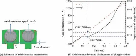
Fig. 15 Method of measuring axial clearance.
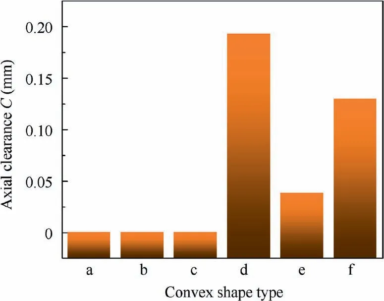
Fig.16 Comparison of axial clearance in different convex shape types.
In addition, there are differences in units and orders of magnitude in each evaluation index, the evaluation indexes can be normalized, that is, the mapping method is adopted to map each evaluation index of the interval [0, 1]. Since the reciprocal values of the pulling-out force and the swing angle are used as the new evaluation indexes, the reciprocal values of each side shall be used in the normalization, as shown in Eq. (2), and the normalized treatment of the axial clearance is shown in Eq.(3),and the mapped analysis matrix k is shown in Eq. (4).
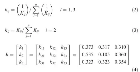
According to the importance of each evaluation index, the fuzzy weight vector W is set as:

where w, wand wrepresent the importance of the pulling force, axial clearance and swing angle respectively. According to the fuzzy analysis method, the Satisfaction matrix E is obtained by multiplying the fuzzy weight vector W and the mapped analysis matrix k, as shown in Eqs. (4)-(6), where erepresents the satisfaction of the No.i scheme. According to the analysis process, the smaller the value, the better. Therefore, according to e<e<e, the best scheme is the Type e, that is, the type of arc and the combination of arc should be preferred for the convex shape.

4.4. Optimization of the rollers structure and spinning parameters
4.4.1. Prioritization scheme
Based on the optimization of slipper structure, the optimization of the roller structure and spinning parameters are carried out. The primary condition for optimizing the process parameters of the plunger component is that the forming quality of the plunger component after the neck-spinning process must meet the relevant technical requirements of the actual production. The main technical requirements are shown in Table 6.
Based on the reliable finite element model, the orthogonal optimization, simulation of neck-spinning process parameters are carried out in this paper. The main optimized process parameters are feed rate f, rotational speed n, roller diameter Dand front angle of roller θ. The orthogonal optimization scheme is shown in Table 7.
4.4.2. Orthogonal simulation, optimization results and analysis
The results of each evaluation index obtained according to the above orthogonal simulation,optimization scheme is shown in Table 8.
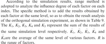
According to the results in the Table 9, the relationship between the different levels of feed rate,rotational speed,roller diameter and swing angle and the evaluation indexes of the neck-spinning process of the plunger component is shown in Fig. 19.

Fig.17 Flowchart of swing angle measurement.
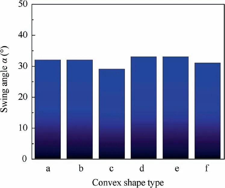
Fig. 18 Comparison of swing angle in different convex shape types.

Table 5 Simulation results of different types of convex shape.

Table 6 Plunger component neck-spinning quality requirements.
As shown in Fig.19(b),the order of the influence of various factors on the axial clearance from large to small is:n,f,θ,and D. According to the strategy that the smaller the axial clearance is, the better the parameter selection, a set of optimal parameters are obtained: f=0.3 mm/r, n=500 r/min,D=50 mm, and θ=30°.
As shown in Fig.19(c),the order of the influence of various factors on the swing angle from large to small is:f,θ,Dand n.According to the strategy that the smaller the swing angle is,the better the parameter selection, a set of optimal parameters are obtained: f=0.03 mm/r, n=100 r/min, D=50 mm,and θ=25°.
In addition,as shown in Fig.19(a),under the same spinning conditions, the impact of feed rate on the pulling-out force is more significant than other spinning parameters. The pulling-out force will increase with the increase of the feed rate,and there is a certain upper limit of the pulling-out force.When the feed rate increases to a certain value, the variation of the pulling-out force will gradually decrease. The largest parameter affecting the axial clearance is the rotational speed,as shown in Fig. 19(b). With the increase of the rotational speed, the axial clearance decreases obviously. It can be seen from Fig. 19(c) that the swing angle is hardly affected by the spinning parameters and the structure of the roller.
From the above analysis, it can be seen that when parameters are selected from different evaluation indexes, the obtained optimal parameters are difficult to be unified, so fuzzy analysis method is still adopted for the optimization of the neck-spinning parameters and the roller structure. The acquisition of evaluation results of the fuzzy analysis method mainly includes two key steps, one is the normalization of data, and the other is the setting of the fuzzy weight vector.
Since the reciprocal values of the pulling-out force and the swing angle are used as the new evaluation indexes, the reciprocal values of each side shall be used in the normalization,as shown in Eq. (2), and the normalized treatment of the axial clearance is shown in Eq. (3), and the mapped analysis matrix k is shown in Eqs. (7)-(10).
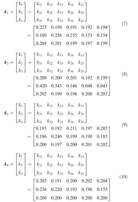
According to the fuzzy mathematical analysis method, the Satisfaction matrix E is obtained by multiplying the fuzzy weight vector W and the mapped analysis matrix k, as shown in Eqs.(13)-(16),where erepresents the satisfaction of the No.i scheme. According to the analysis process, the smaller the value, the better.
The next time I was at the store, I bought a few more packs. I gave some of the cards to my eight-year-old son, who was also a baseball fan. We often played out in the yard, hitting a Nerf ball with an oversized plastic bat. Now we had an indoor sport that we could share as well.

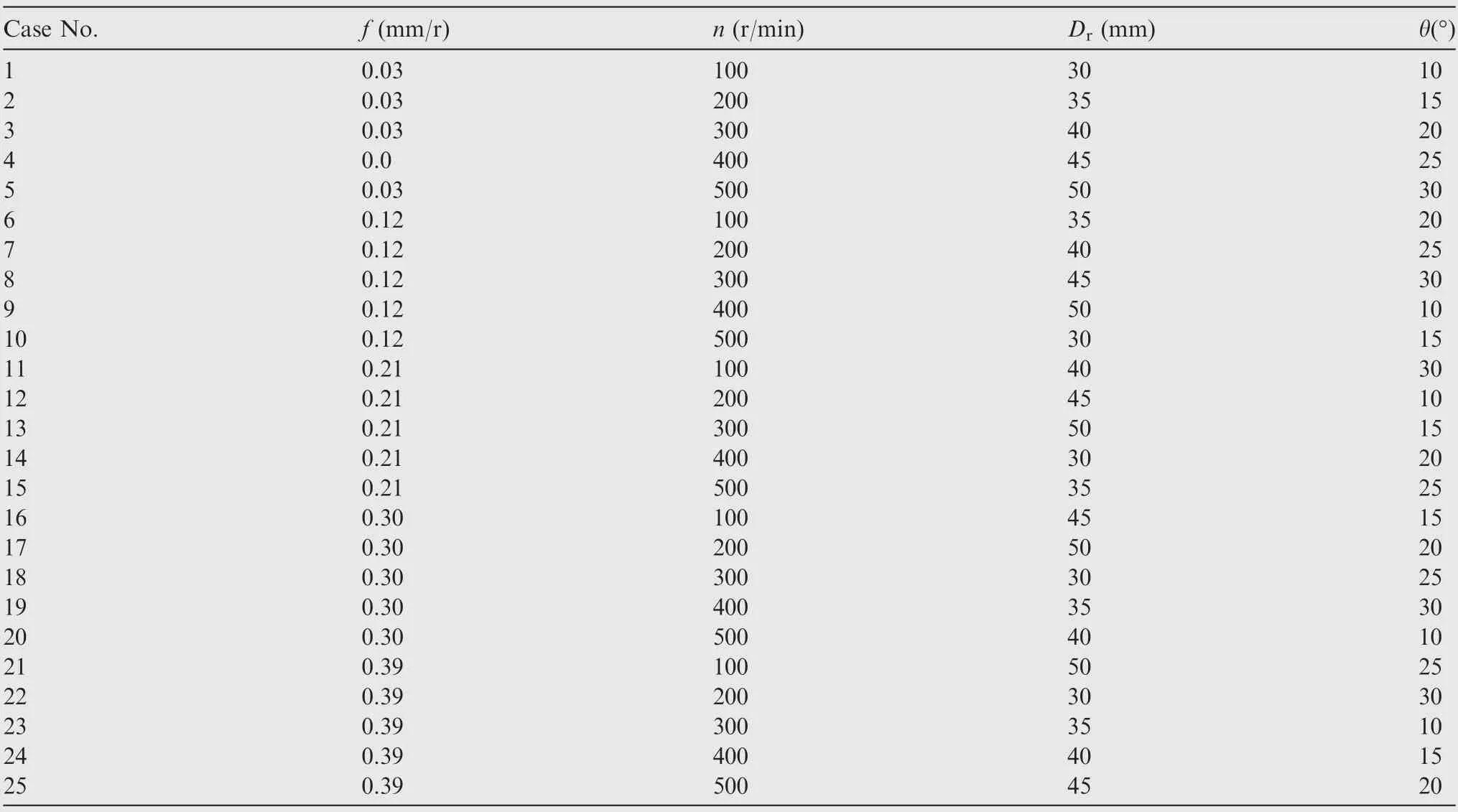
Table 7 Orthogonal optimization scheme of process parameters.
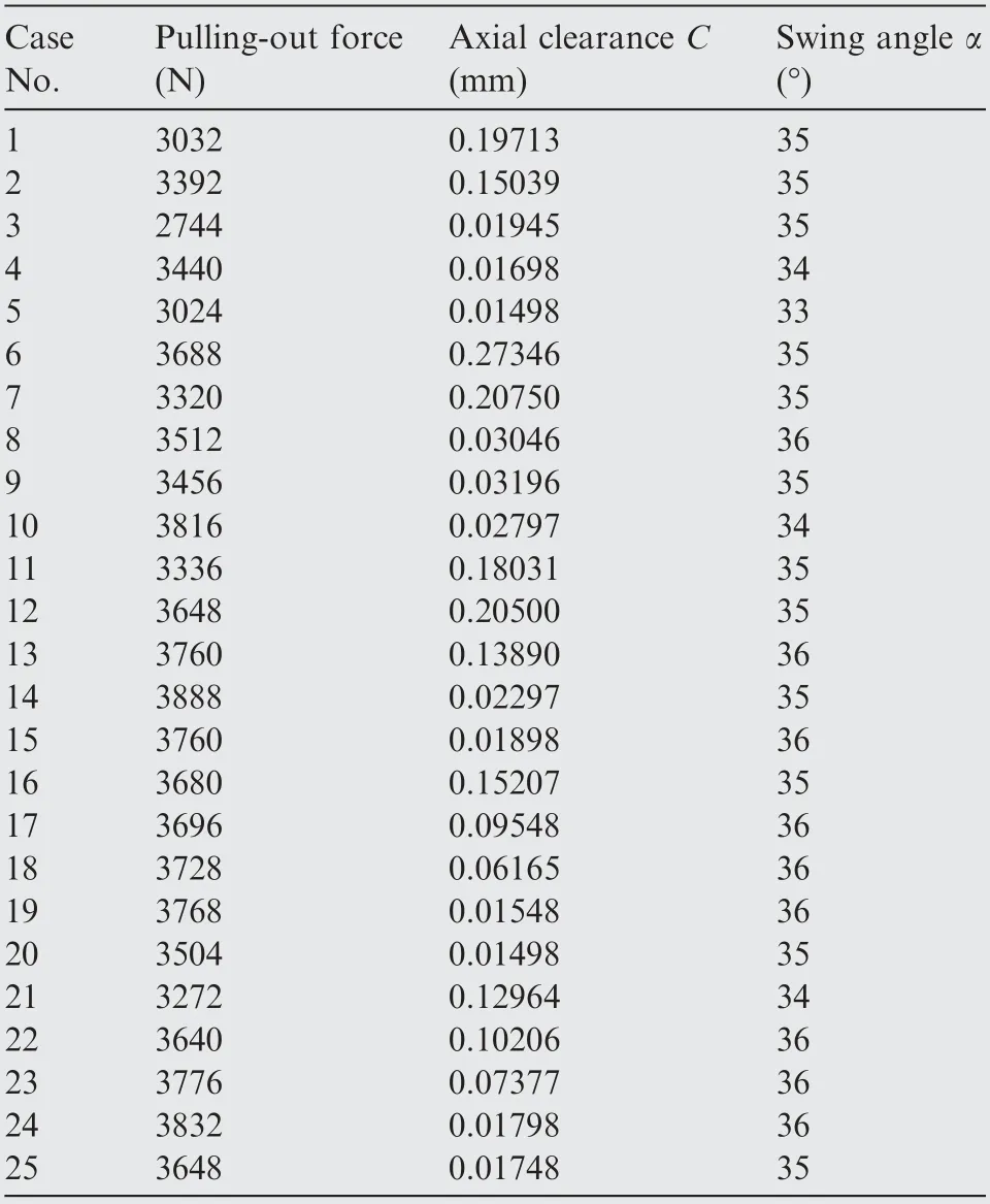
Table 8 Results of orthogonal simulation optimization.
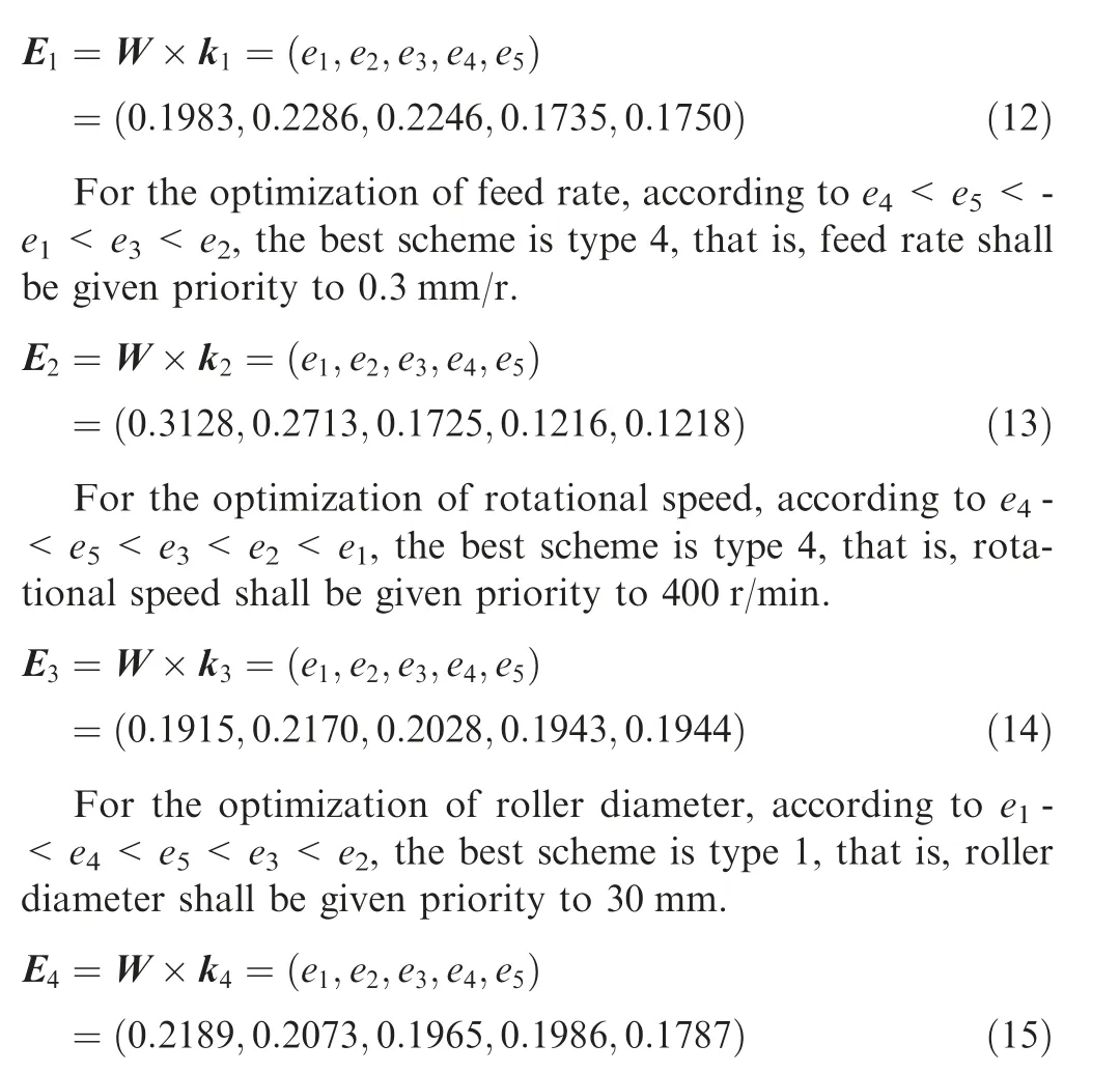
For the optimization of the front angle of roller θ, according to e<e<e<e<e, the best scheme is type 5, that is, front angle of roller θ shall be given priority to 30°.
To sum up, the optimal results of spinning parameters and roller structural parameters obtained through orthogonal simulated optimization are: f=0.3 mm/r, n=400 r/min,D=30 mm, and θ=30°.
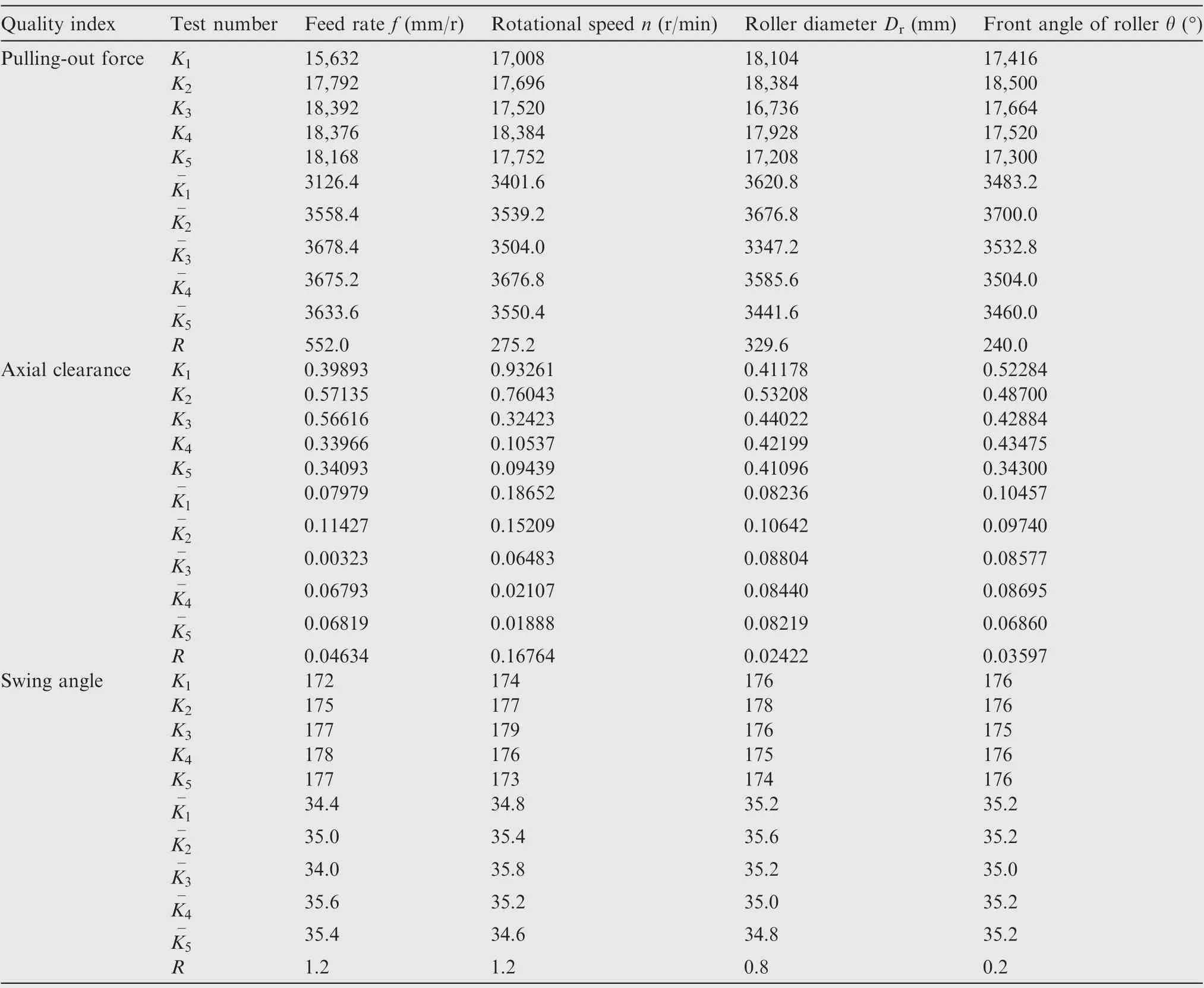
Table 9 Result of orthogonal simulation is optimized by range method.
4.5. Confirmation simulation
The combination of the optimized slipper structure, spinning parameters and roller structure obtained above is applied in the FEA model for the validation process. The simulation results of pulling-out force P, axial clearance C and swing angle α were obtained as follows.
(1) Pulling-out force
Fig.20(a)demonstrates the curves of the axial pulling force Pand plunger displacement l obtained by FEM after the neck-spinning process under the optimized process parameters above. It can be seen that a constant loading rate of 2000 N/s is applied to the plunger, when the plunger moves 1.962 s, the plunger reaches the critical point of breaking away from the slipper.That is,the pulling-out force P reaches the peak value of 3924 N, it meets the technical requirement that the pullingout force should be more than 2500 N.
(2) Axial clearance
Fig. 20(b) shows the curves of the axial contact force Fbetween the plunger and slipper contact inner surface and the plunger displacement l obtained by FEM after the neckspinning process of the plunger component under the optimized process parameters above.In this FEA model,a constant moving speed of 1 mm/s is applied to the plunger,it can be seen that when the plunger moves 0.0145 s, the direction of the axial force has changed,indicating that the displacement of the plunger moves at this time is the axial clearance(about 0.0145 mm),which can be obtained from the intersection point on the red dotted line at 0.0145 s. It meets the technical requirement of axial clearance not exceeding 0.025 mm.
(3) Swing angle
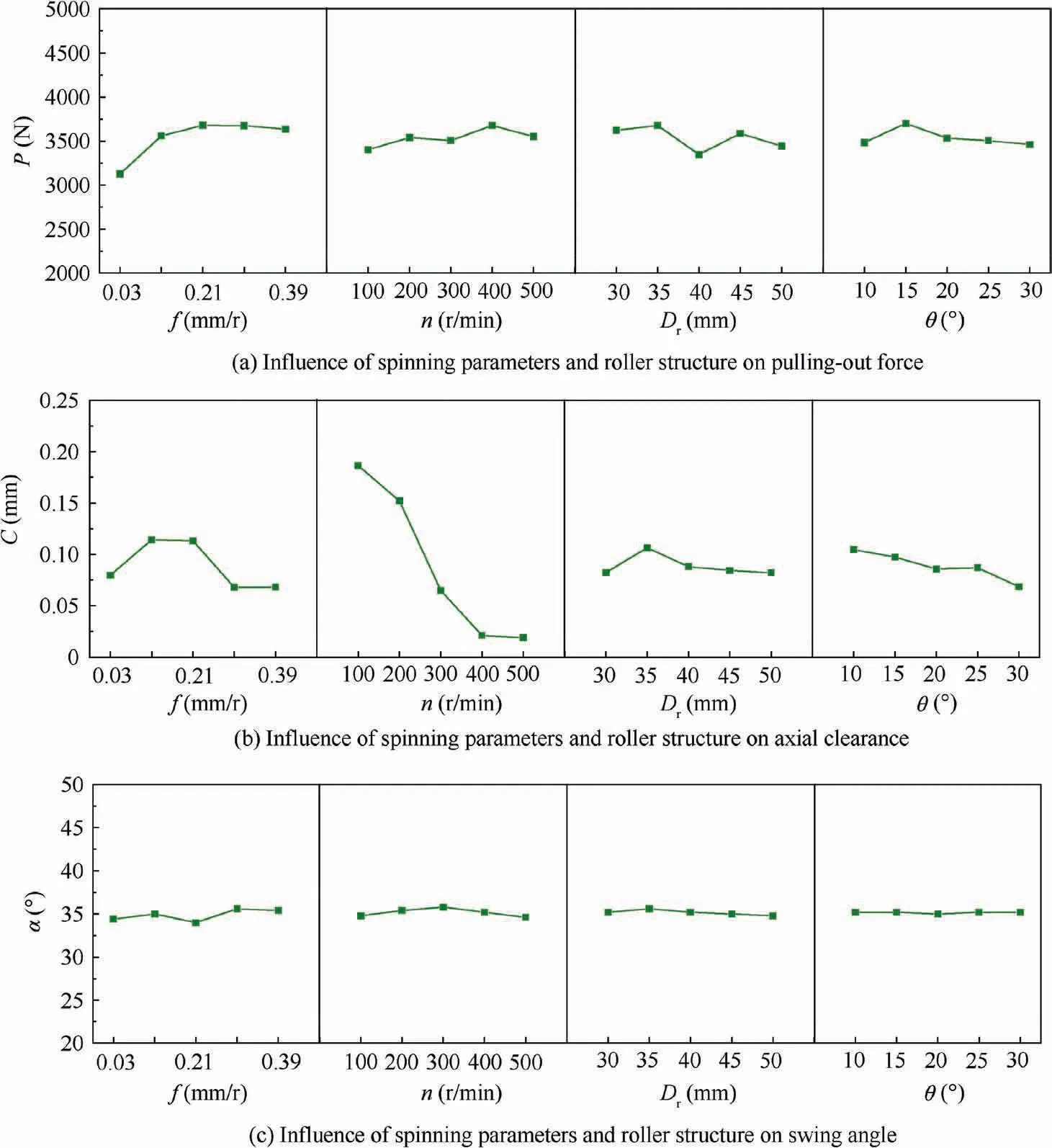
Fig. 19 Effect of spinning parameters and roller structure on neck-spinning quality.
Fig. 20(c) shows the swing angle of the plunger component obtained by neck-spinning simulation under the optimized process parameters. Its value is 36°, which meets the technical requirement that the swing angle is not less than 35°.
5. Conclusions
In this study, a reliable finite element model for the quality analysis of the plunger component after the neck-spinning process has been proposed. The neck-spinning tests were carried out on the plunger component to verify the finite element analysis (FEA) model, which is used to analyze the neckspinning process of different roller structure (front angle of the roller and roller diameter), slipper structure and spinning parameters (feed rate and rotational speed). The influence of process conditions on the neck-spinning quality (axial clearance C, pulling-out force P and swing angle α) is analyzed.And the neck-spinning process parameters were optimized through the combination of range method and fuzzy mathematical analysis method. The main conclusions are as follows:
(1) A novel FEA model for the prediction of the neckspinning quality of the plunger component is established and verified by the experimental results. The simulation results are in good agreement with the experimental results within 15% errors.
(2) The neck-spinning simulations have been carried out on the slipper with different convex shapes under the same spinning conditions, and the simulation results are analyzed and calculated based on the mathematical fuzzy analysis method. It is found that the best neckspinning quality can be obtained when the convex shape of the slipper is a combination of arcs and arcs.
(3) The orthogonal simulations have been carried out to analyze the influence of roller structure and spinning parameters on the neck-spinning quality. And the roller structure and spinning parameters are optimized by the combination of range method and fuzzy mathematical analysis method.It is found that the reasonable spinning parameters and structure of roller for the plunger component are: feed rate f of 0.3 mm/rev, rotate speed n of 400 rev/min, roller diameter Dof 30 mm, and front angle of the roller of 30°.
(4) Under the same spinning conditions,the impact of feed rate on the pulling-out force is more significant than other spinning parameters.Rotational speed has the largest impact on the axial clearance,and the swing angle is hardly affected by spinning parameters and the structure of the roller.
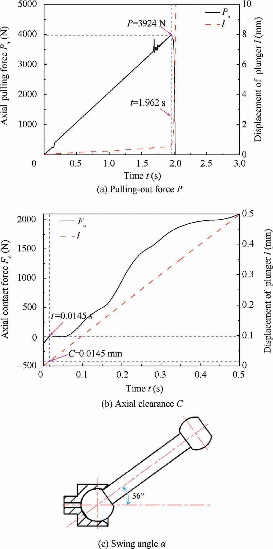
Fig. 20 Confirmation simulation results.
Declaration of Competing Interest
The authors declare that they have no known competing financial interests or personal relationships that could have appeared to influence the work reported in this paper.
Acknowledgment
This study was supported by the National Natural Science Foundation of China for Creative Research Groups (Grant No. 51921003).
 CHINESE JOURNAL OF AERONAUTICS2021年4期
- CHINESE JOURNAL OF AERONAUTICS的其它文章
- Time delay compensation in lateral-directional flight control systems at high angles of attack
- Dual stability enhancement mechanisms of axial-slot casing treatment in a high-speed mixed-flow compressor with various tip clearances
- Development cost prediction of general aviation aircraft using combined estimation technique
- Improvement on shaped-hole film cooling effectiveness by integrating upstream sand-dune-shaped ramps
- Modeling and parameter identification of linear time-varying systems based on adaptive chirplet transform under random excitation
- An experimental method to obtain the hard alpha anomaly distribution for titanium alloy aeroengine disks
