Analytical model of cutting force in axial ultrasonic vibration-assisted milling in-situ TiB2/7050Al PRMMCs
Xiaofen LIU, Wenhu WANG, Ruisong JIANG, Yifeng XIONG,Kunyang LIN, Junchen LI, Chenwei SHAN
a Key Laboratory of High Performance Manufacturing for Aero Engine, Ministry of Industry and Information Technology, School of Mechanical Engineering, Northwestern Polytechnical University, Xi’an 710072, China
b Engineering Research Center of Advanced Manufacturing Technology for Aero Engine, Ministry of Education, School of Mechanical Engineering, Northwestern Polytechnical University, Xi’an 710072, China
c School of Aeronautics and Astronautics, Sichuan University, Chengdu 610065, China
KEYWORDS Al-MMCs;Analytical model;Cutting force;In-situ;Milling;TiB2 particles;Ultrasonic vibration
Abstract Ultrasonic vibration-assisted milling has been widely applied in machining the difficultto-cut materials owing to the remarkable improvements in reducing the cutting force. However,analytical models to reveal the mechanism and predict the cutting force of ultrasonic vibrationassisted milling metal matrix composites are still needed to be developed.In this paper,an analytical model of cutting force was established for ultrasonic vibration-assisted milling in-situ TiB2/7050Al metal matrix composites. During modeling, change of motion of the cutting tool, contact of toolchip-workpiece and acceleration of the chip caused by ultrasonic vibration was considered based on equivalent oblique cutting model. Meanwhile, material properties, tool geometry, cutting parameters and vibration parameters were taken into consideration.Furthermore,the developed analytical force model was validated with and without ultrasonic vibration milling experiments on in-situ TiB2/7050Al metal matrix composites.The predicted cutting forces show to be consistent well with the measured cutting forces. Besides, the relative error of instantaneous maximum forces between the predicted and measured data is from 0.4%to 15.1%.The analytical model is significant for cutting force prediction not only in ultrasonic-vibration assisted milling but also in conventional milling in-situ TiB2/7050Al metal matrix composites, which was proved with general applicability.
1. Introduction
To satisfy increasing demands of thrust and fuel efficiency for gas turbine engines,in recent years,many innovative materials such as titanium alloy,nickel-based alloy,high temperature alloy,ceramics,compositeshave been developed and used in the aeronautics and astronautics field and other industries. Among these new materials, the in-situ TiB/7050-Al metal matrix composites (MMCs) is becoming a promising material for high performance aero-engine due to its excellent properties such as improved strength, low density and increased wear resistance.As hard ceramic particles in the matrix material, it shows characteristic of machining difficult-to-cut materials such as terrible tool wear and large cutting force during conventional cutting process.Compared with conventional cutting, ultrasonic vibration-assisted cutting has the remarkable advantages of prolonging tool life,reducing surface roughnessand cutting forceand has been one of the most important cutting method for MMCs. However, due to the change of cutting tool motion and the material removal mechanism, the cutting force generation and component is quite different in ultrasonic vibrationassisted cutting process. In order to have a better understanding of the effect of ultrasonic vibration on the material removal process and cutting force, it is needed to develop a cutting force model to predict the cutting force for ultrasonic vibration-assisted milling (UVM) the in-situ TiB/Al 7050 MMCs.
In order to reveal the mechanism of reduction of cutting force, Ni et al.performed an analytical model to calculate the contact rate between the cutting tool and the workpiece in the UVM process. The results showed that the separation of tool-workpiece caused by ultrasonic vibration was the main reason for the reduction of cutting force.
From another perspective, Shen et al.and Ding et al.developed force models to predict cutting force with consideration of instantaneous chip thickness in UVM. The results showed that intermittent cutting had remarkable influence on instantaneous chip thickness and thus resulted in cutting force reducing. Tao et al.made a cutting force model by considering uncut thickness based on UVM experimental data.And the results showed that cutting force was dramatically affected by the feed rate, vibration amplitude, the ratio between the vibration frequency and the rotation speed. The model could express the relationship between cutting force and the process parameters.
Besides, Elhami et al.developed an analytical model to predict the mean cutting force for a hybrid milling process between the thermally enhanced machining and UVM. The model was taken into consideration of chip thickness and thermal softening effect,which was proved greatly by experimental results.Verma et al.proposed a static cutting force model to study the effect of ultrasonic vibration on the mean cutting force in the axial UVM. The model was considered the effect of acoustic softening on flow stress by modifying the Johnson-Cook (J-C) model and analyzed the change of the cutting motion by calculating the tool-workpiece contact rate.The results indicated that ultrasonic vibration could result in flow stress changing which has significant influence on the cutting force.
Viewed from the previous studies, researches are mainly focused on the effect of ultrasonic vibration on the chip thickness and the influence of acoustic softening on the material’s property during the cutting force modeling in UVM.However,beyond that there are obvious changes in the motion of the cutting tool and the contact of tool-chip-workpiece due to the role of ultrasonic vibration, which would have significant influence on the cutting force.In this paper,a novel analytical cutting force model is developed with consideration of contact of tool-chip-workpiece, material properties and geometry of the cutting tool for the axial UVM. The coupled effect of tool-chip-workpiece is analyzed based on discrete method and equivalent oblique cutting. In order to validate the force model, a series of milling experiments with and without ultrasonic vibration are carried out on the TiB/7050Al particle reinforced metal matrix composites.
2. Cutting force modeling
2.1. Principle of axial UVM
The axial UVM is a machining technology that is based on the conventional milling (CM) with assistance of ultrasonic vibration along the axial direction of the spindle. In this study, the ultrasonic vibration with sinusoidal signal is imposed on the cutting tool, which could make the cutting tool vibrate with high frequency and low amplitude during machining. The schematic diagram of axial ultrasonic vibration-assisted milling is shown in the Fig. 1.
Due to the application of ultrasonic vibration, the cutting tool generates hybrid motion with rotation motion, feed motion and oscillation motion. The complicated motion of the cutting tool can be defined by a motion equation of a random point on the cutting edge, which is described as follow:

where vis the feed velocity, R is the radius of the cutting tool, ω is the angular velocity of the spindle, t is the cutting time,A and f is the vibration amplitude and frequency,respectively. It shows that the trajectory of the cutting tool is sinusoidal cycloid style.
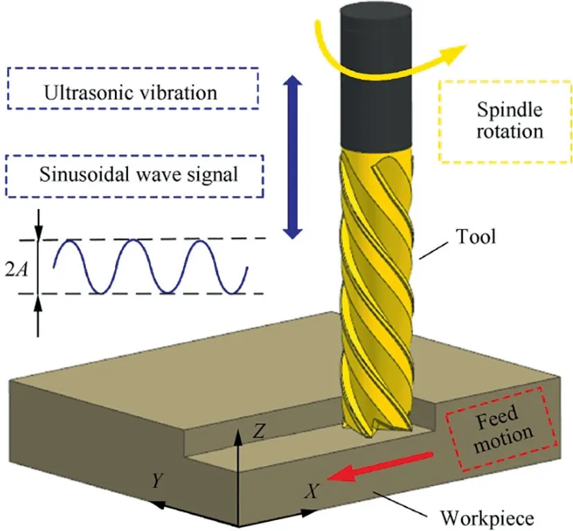
Fig. 1 Schematic diagram of axial UVM.
2.2. Analysis of cutting force
Due to the hybrid motion and complex geometry of the cutting tool, the chip thickness is varied with change of time, which has significant effect on the cutting force during the machining process. It is considered that the milling tool is resolved many equal slices with the same height dz along axial direction which is shown in Fig.2(a).And machining of each slice participated is regarded as oblique cutting process. The total cutting force could be calculated by sum of the cutting force of the each layer, which is shown in Fig.2(b), where fis the feed rate per tooth, θ(z) is the instantaneous immersion angle of the slice at axial position z, dF, dFand dFis the tangential,radial and axial cutting force of one slice dz in milling,respectively.
Due to the application of ultrasonic vibration, a certain amount of change creates in the oblique cutting process,which will be analyzed in detail in the Section 3. In this study, the total cutting force of the milling tool is given as follow:

where F, Fand Fare the cutting force components of the tangential, radial and axial force in the kth flute and the jth slice, respectively. θ(t) is the angular position of the cutting point of the kth flute in the jth slice. The index of the slices j=1, 2, 3, ···, r, where r is the number of the slices.The index of the flutes k=1,2, 3, ···, N, where N is the number of the teeth of the cutting tool.Rrefers to the contact rate between the cutting tool and the workpiece,which is defined as Ref.:

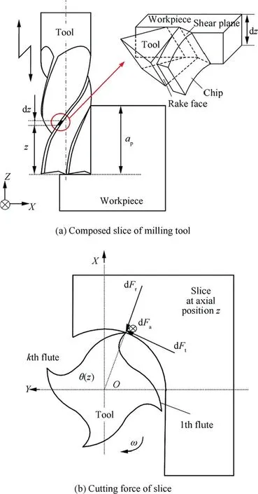
Fig. 2 Schematic diagram of cutting force on tool.
where v is cutting speed,β is mill helical angle,and the coefficient 1/2 expresses that the cutting tool participates in impacting the workpiece with half period in one vibration period.
3. Equivalent oblique cutting mechanism
Based on the analysis above,it is important to understand and analyze material removal and cutting force of the slice for cutting force modeling. In other words, the equivalent oblique cutting process is significant for building cutting force model,which is expressed as Fig. 3. During cutting process, the relative motion between the cutting tool and the workpiece is occurred generally, it is considered that the workpiece is fixed without moving. From Fig.3(a), the velocity of a random point of cutting edge includes cutting speed v and vibrating velocity valong the axial direction, which can be described as follow:

where D is tool diameter,nis the spindle rotation speed.Aiming at modeling the cutting force,the slice dz of cutting edge is equivalent to the oblique cutting and the Cartesian coordinate system XYZis built, which is shown in Fig.3(b).
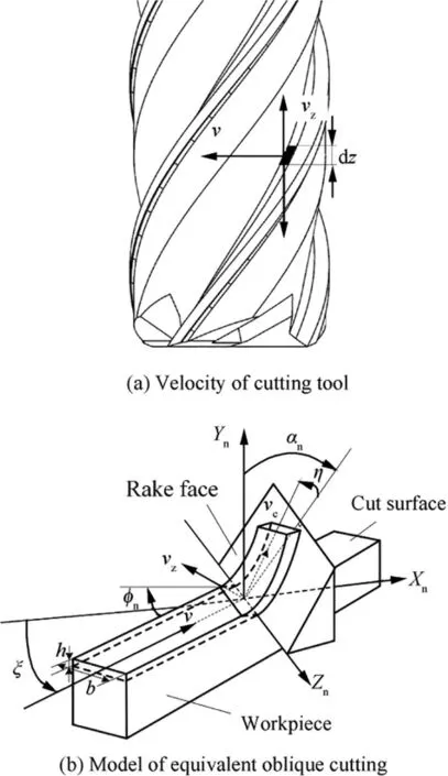
Fig. 3 Schematic diagram of equivalent oblique cutting.
3.1. Velocity analysis
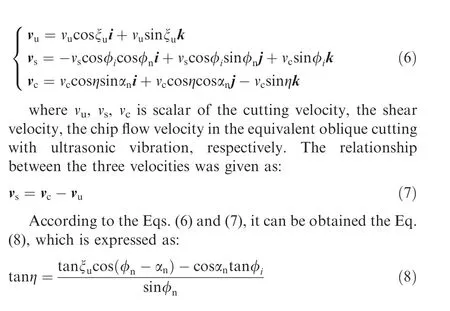
With adding ultrasonic vibration, the cutting velocity of cutting tool vand the angle between the cutting edge and the X axial ξis created, which is defined as:
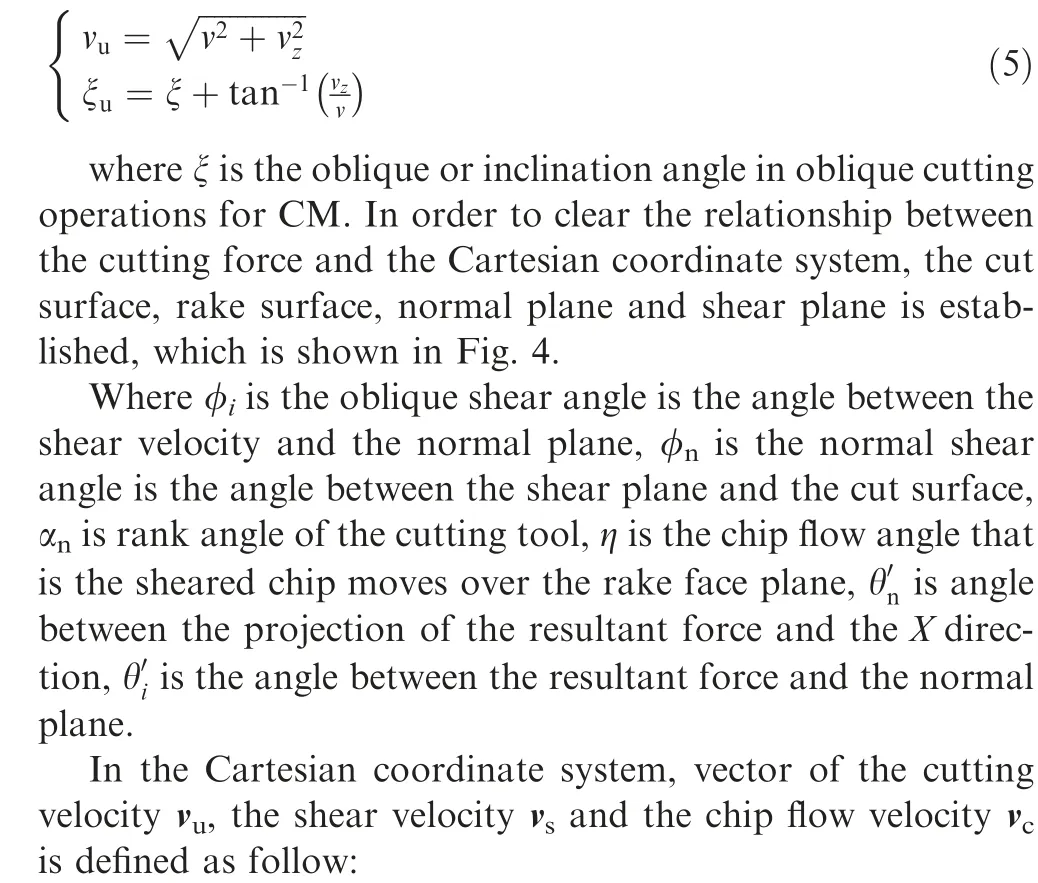
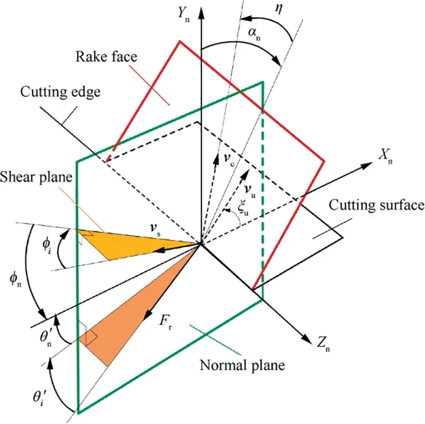
Fig. 4 Velocity analysis of equivalent oblique cutting.
3.2. Forces analysis
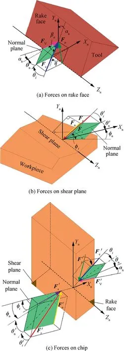
The cutting force is the main factor for the material removal during cutting process. For better understanding the cutting force, in this study, the forces applied to the rake face, the shear plane and the chip are analyzed, respectively, which are shown in Fig. 5.
3.2.1. Forces applied to the rake face
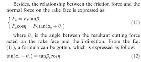
On the rake face,the resultant cutting force Fis composed of frictional force Fand normal force F, which is shown in Fig.5(a). The friction force is produced by the chip flowing along the rake face.The relationship between the friction force and the cutting force is expressed as follow:

where βis the friction force and θis the angle between the resultant cutting force acted on the rake face and the normal plane. From the Eq.(9), the following equation can be obtained:

3.2.2. Forces applied to the shear plane
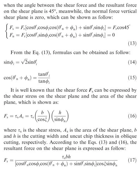
The resultant force Fapplied on the shear plane is composed of shear force Fand normal force Fvertical the shear plane,which is shown in Fig.5(b). Based on the maximum shear stress principle in Ref.,the maximum shear force occurs
3.2.3. Forces applied to the chip
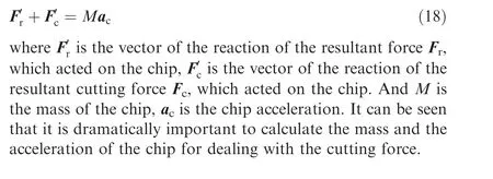
According to Newton’s Third Law of Motion,action and reaction is equal in magnitude and opposite in direction.Then the forces on the rake face and forces on the shear plane is equivalent to the chip, which is described as Fig.5(c). Generally, in the conventional oblique cutting, the cutting force is equal to the resultant force on the shear plane, the acceleration of the chip is without consideration, and it means that the inertial effect of chip is ignored. However,during ultrasonic vibration assisted cutting, due to the ultrasonic vibration, it makes the chip obtain some kinetic energy. Furthermore, the chip between the rake face and the shear plane gets acceleration which is necessary to take into consideration. As a result, a new force balance between the chip,shear plane and rake face is described:
3.3. Analysis of mass and acceleration of the chip
3.3.1. Mass of the chip
To get the cutting force of the chip, it is important to analyze the mass and acceleration of the chip.For calculating the mass of the chip between the rake face and the shear plane,the volume of the chip is analyzed,the schematic diagram of mass calculation is shown in Fig. 6.
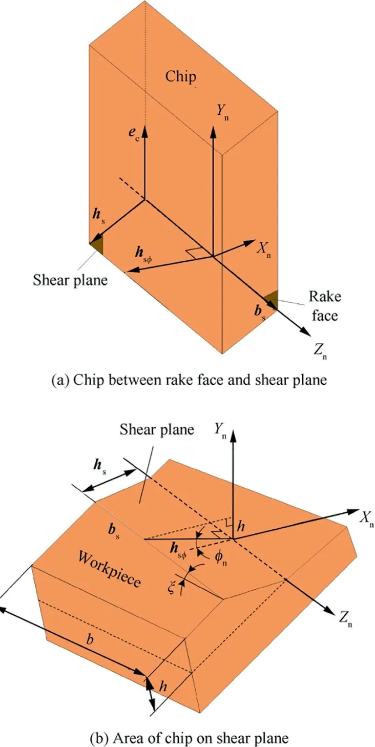
Fig. 6 Schematic diagram of mass calculation.
The chip can be described by the vector (h, b, e) Ref.,which is shown in Fig.6(a). The volume of the chip per unit length Vcan be calculated as follow:
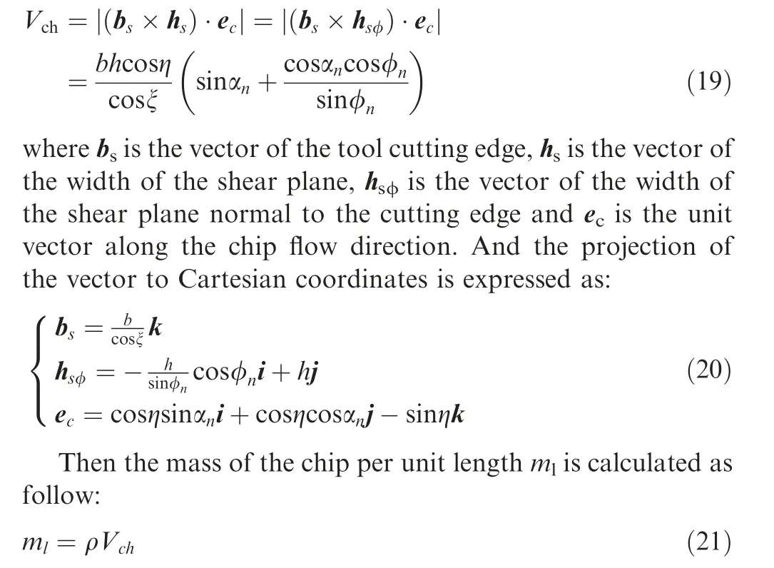
where ρ is the density of the workpiece material.According to the theory of orthogonal cutting, the contact length between the chip and the rake face lis expressed as Ref.:


3.3.2. Chip acceleration
During the cutting process, mass conservation is performed before and after materials deformation. The schematic diagram of the chip deformation is shown in Fig. 7.
According to the law of mass conservation, it can be obtained the equation as follow Ref.:
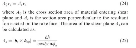
The across area of the chip Aalong the chip flow direction is calculated as the equation:
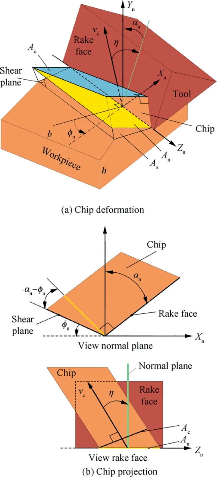
Fig. 7 Schematic diagram chip deformation.
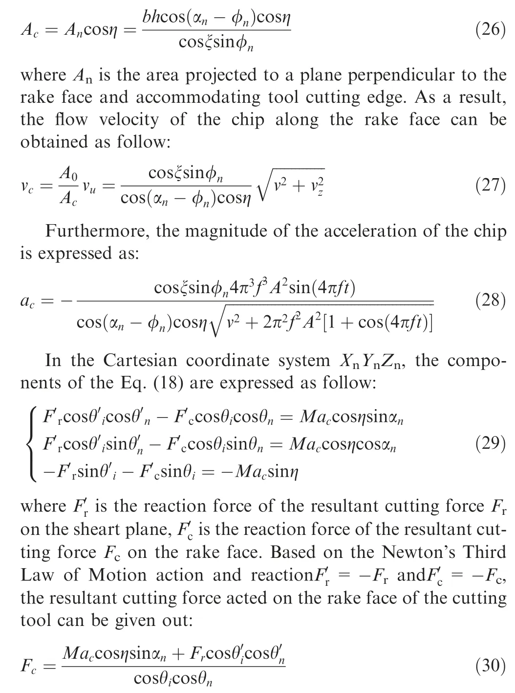
4. Prediction of milling force
In order to get the cutting force model, it is needed to transform the forces in the oblique cutting process to the milling process. From the analysis above, in oblique cutting process the vector of the resultant force on the rake face can be expressed as follow:
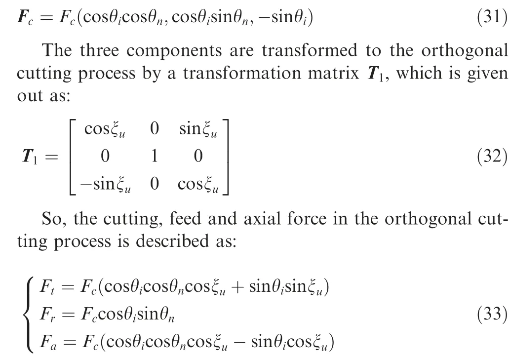
In milling forces,it is assuming that cutting process is keeping stable, the height of cutting tool participated in cutting is resolved into the same r slices, the height of every slice dz is calculated as:
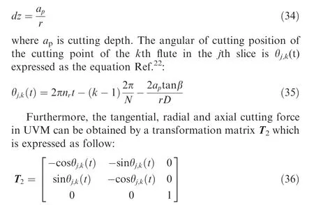
Then, taking the Eqs. (17), (30), (33) and (35) into the Eq.(2),the cutting force is calculated by MATLAB,the flowchart of the methodology for cutting force calculation is shown in Fig. 8.
5. Experimental validations
To prove the analytical cutting force model, a set of experiments were carried out on a VMC-850 CNC machine with and without ultrasonic vibration. Cutting conditions of all experiments were down milling and dry cutting, experimental setup is presented in Fig. 9. Ultrasonic vibration equipment is mainly consisted of three parts including the ultrasonic generator, non-contact electromagnetic unit and ultrasonic tool holder. In this study, the vibration frequency was 21 kHz and vibration amplitude was 4 μm. The details of the cutting parameters of validated experiments are listed in Table 1. A set of single-factor tests with and without ultrasonic vibration were performed to investigate the influence of cutting parameters on cutting force, the detailed levels of cutting parameters investigated are listed in Table 2. The measuring equipment used included 9255B Kistler 3D force measuring platform,charge amplifier, data collector and computer. The tools used in the experiments were 4 flutes TiAlN coated carbide end milling tools. The diameter of cutting tools included 12 mm and 7 mm which were used in validated experiments. The cutting tool of 7 mm was used to the single-factor test. The geometrical parameters of the cutting tool were listed in Table 3.
In this study,the material used is TiB/7050Al MMCs with 6wt%TiBparticles,the size of the particles varies from 50 to 200 nm, and the nominal chemical composition (wt%) of the 7050Al alloy matrix is expressed in the Table 4, the material’s constitutive parameters are presented in Table 5, the mechanical and physical properties of the material are listed in Table 6. It could be seen that the main element in the in-situ TiB/7050Al MMCs is aluminum and its elongation is 6%, it shows ductility. However, machining the in-situ TiB/7050Al MMCs is a rather complex work owing to the reinforcement particles embedded in the matrix are highly abrasive and responsible for complex deformation behaviour,severe tool wearand poor surface integrity.According to the previous study on its machinability, the insitu TiB/7050Al MMCs is regarded as one of the typical difficult-to-cut materials.
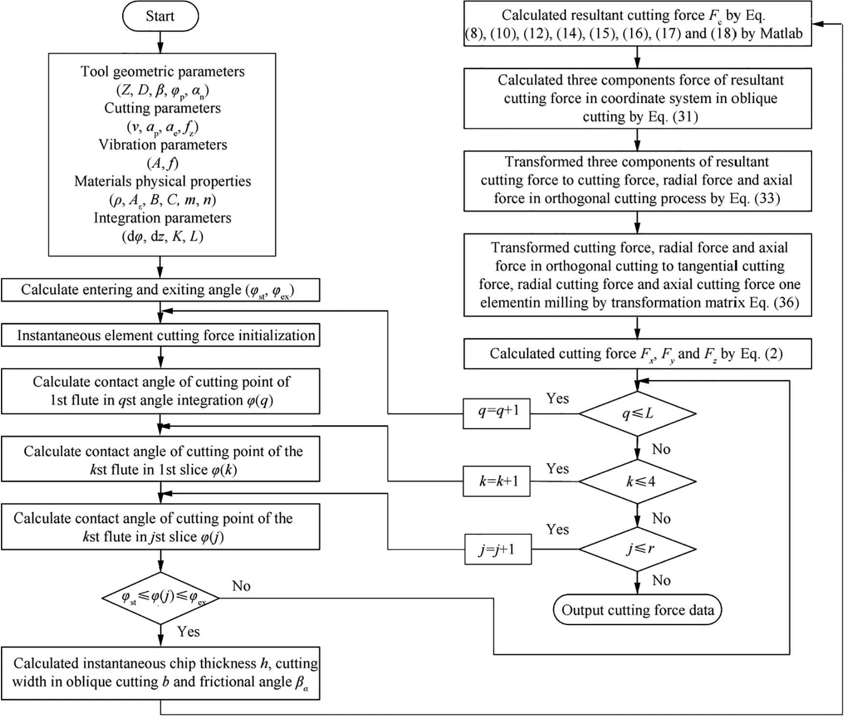
Fig. 8 Flowchart of methodology used for calculation of cutting force.
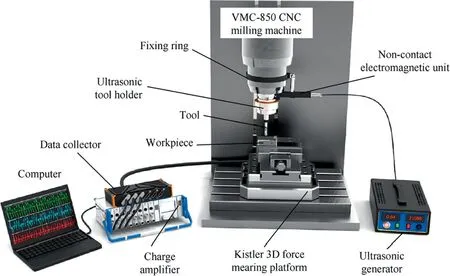
Fig. 9 Schematic diagram of experimental setup.
6. Results and discussions
The proposed model for predicting the cutting forces in UVM process is validated by comparing the predicted cutting forces with the experimentally measured ones in the UVM test#1 and test#2,the cutting force components F,Fand Fin the X,Y and Z directions during one revolution of the milling tool are shown in Fig.10.Besides,the cutting force components F,Fand Fin CM during one revolution of the milling tool are shown in Fig. 11. It can be seen that the results show a good agreement between the predicted and measured cutting forces of UVM in both the variation trend and its magnitude.

Table 1 Experimental parameters of validated experiments.

Table 2 Experimental parameters and levels of single-factor tests.

Table 3 Specifications of coated carbide milling tool.

Table 4 Nominal chemical composition of the 7050 Al alloy matrix.26

Table 5 Material’s constitutive parameters of TiB2/7050Al MMCs.27
In this analytical force model, when the parameters of vibration amplitude and frequency are set to be 0 the machining becomes CM process, the experimental results and predicted results in frequency and amplitude of 0 in test #3 and test #4. The results show that the force model can be used to predict the cutting force for CM, and the cutting forces calculated by the model are in reasonable agreement with that measured in experiments in CM. Besides, it could be noticed from Figs. 10 and 11 that the measured cutting forces tend to fluctuate regularly, comparing to the relative smooth predicted cutting forces. There are two possible reasons for the deviation for the measured and predicted cutting forces.First,actually, the material in-situ TiB/7050Al MMCs is heterogeneous because of the reinforcements. During experiments,the cutting tool comes into contact with the different compositions of the material,it might result in measured cutting forces fluctuating. However, during modeling, the in-situ TiB/7050-Al MMCs is regarded as a homogeneous material due to the content and size of the particles is very small,the predicted cutting forces is shown relative smoothly. Second, in the actual machining process,the tool deflection,cutting process dynamics, machine vibrations and so forth might have effect on the measured cutting force, which would make the measured cutting forces tend to fluctuate,however,these factors are ignored in the developed cutting force model.Furthermore,it could be observed that the fluctuations tend to be greater when using the cutting tool with a diameter of 7 mm. This might be because length to diameter ratio is bigger and the contact length that is in the tool holder is smaller when the cutting tool is 7 mm. A research has shown that length to diameter ratioincreases and contact length decreases the interface stiffness and damping between the tool and tool holder decreases,which has significant influence on the tool deflection and cutting process dynamics.

Table 6 Mechanical and physical properties of TiB2/7050Al MMCs.28
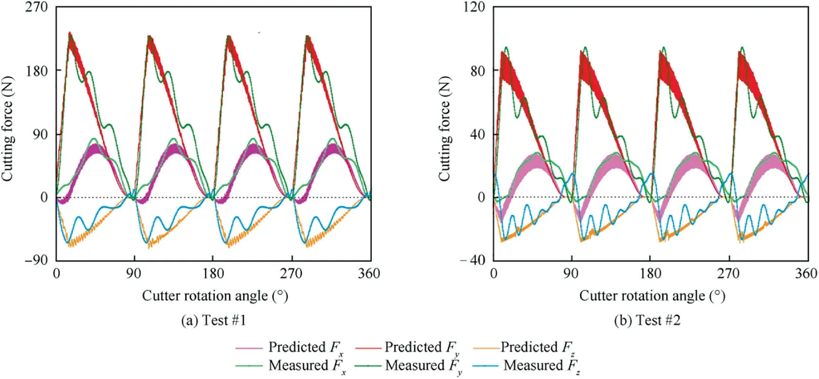
Fig. 10 Comparison of cutting forces between predicted and experimental data of UVM.
In Fig.12,the instantaneous maximum forces and their relative error of the cutting forces components F,F,Fand the resultant cutting force of the components F are shown. The resultant cutting force F can be expressed as follow:

From Fig.12(a),the instantaneous maximum force components F,F,Fand the resultant cutting F measured in test#1 in UVM is 83.22 N, 227.48 N, 64.23 N and 250.60 N, respectively. And the corresponding predicted cutting force results of F, F, Fand F are 76.13 N, 234.41 N, 72.85 N and 257.00 N, respectively. The relative errors of F, F, Fand F are 8.5%, 3.4%, 13.4% and 2.5%, respectively.
From Fig.12(b),the instantaneous maximum force components F,F,Fand the resultant cutting F measured in test#2 in UVM is 27.81 N, 94.04 N, 26.71 N and 101.64 N, respectively. And the corresponding predicted cutting force results of F, F, Fand F are 26.97 N, 91.69 N, 28.36 N and 99.69 N, respectively. The relative errors of F, F, Fand F are 3.0%, 2.5%, 6.1% and 1.9%, respectively.
From Fig.12(c),the instantaneous maximum force components F,F,Fand the resultant cutting F measured in test#3 in CM is 77.19 N, 288.52 N, 90.76 N and 312.15 N, respectively. And the corresponding predicted cutting force results of F, F, Fand F are 76.87 N, 305.58 N, 104.43 N and 331.95 N, respectively. The relative errors of F, F, Fand F are 0.4%, 5.9%, 15.1% and 6.3%, respectively.
From Fig.12(d),the instantaneous maximum force components F,F,Fand the resultant cutting F measured in test#4 in CM is 37.36 N, 112.64 N, 34.30 N and 123.53 N, respectively. And the corresponding predicted cutting force results of F, F, Fand F are 37.08 N, 115.01 N, 38.07 N and 126.69 N, respectively. The relative errors of F, F, Fand F are 0.7%, 2.1%, 10.9% and 2.6%, respectively.
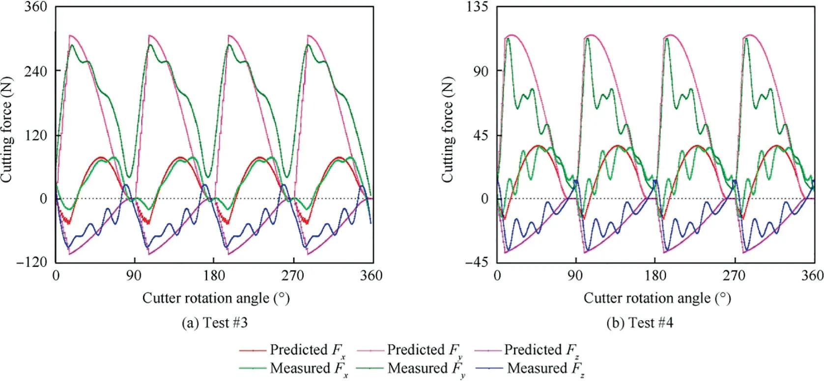
Fig. 11 Comparison of cutting forces between prediction and experiment data of CM.
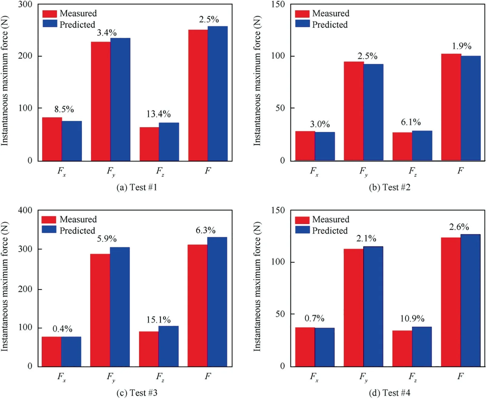
Fig. 12 Relative error of instantaneous maximum forces between predicted and experimental data of UVM and CM.
It can be seen that the relative error of instantaneous maximum forces between predicted and experimental data of UVM and CM is less than 10% for the forces F, Fand F.However, the maximum relative error of force components Fis 15.1%.A literature had shown that the force Fwas easily influenced by the environment which would result in a larger error.In actual machining process, the error-sources from environment may include deflection of cutting tool, stiffness of tool holder, force-chatter, machine vibration, and so forth.Tool deflection comes from manufacturing and installing milling tool, and it is significantly influenced by the stiffness of tool holder. Force-chatter results from rotation errors of the spindle, fixture and workpiece and so on, which would cause machine vibration. All of them would result in machining error which is effective to influence the cutting force error.Besides, the smaller cutting force is more significantly influenced by the environment.And many researchesof cutting force also indicates that the error of force Fis relative larger and it is easily influenced by environment.In this study,the main reason for the error is the measuring equipment and experimental environment.
Additionally, the results show that the cutting force in UVM (test #1 and test #2) is smaller than cutting force in CM (test #3 and test #4), respectively, which is shown in Table 7 and Fig.13(a). It indicates that it would contribute to reducing cutting force by applying ultrasonic vibrationassisted milling in-situ TiB/7050Al composites. In order to have a deep understanding of the cutting force reducing between UVM and CM, the percentage of force reduction Pcould be calculated as follow:

where ΔF is the amount of reduction of the resultant cutting force F, Fand Fis the resultant cutting force in CM and UVM,respectively.Compared with CM,it could be found that the maximum resultant force could be reduced by about 20% during UVM in-situ TiB/7050Al composites, which is expressed as in Table 7 and Fig.13(a). According to analysis in Section 3.2.3, the reason for the reduction of cutting force might be the inertia force of chip caused by the ultrasonic vibration. The force equilibrium relation for the chip is reformed by considering the inertial effect of chip because the relative motion between the cutting tool and workpiece in UVM is changed by adding ultrasonic vibration. Due to addition of the inertial force, the cutting force is reduced during UVM.
However, in this paper, besides the influence of the inertial effect of chip removal process, the contact rate between the cutting tool and workpiece is considered during cutting force modeling. Hence, it is quite important to make clear that the proportion of the cutting force reduced is determined by the inertial force of the chip. From the Eq. (2), it could be found that the contact rate of tool-workpiece has an effect on the force F, and the reduction of Fis relative small. It could be achieved the approximate proportion Pby estimating ratio of reduction of the resultant cutting force Fto reduction of the resultant cutting force F,approximate proportion Pcould be calculated as follow:


Table 7 Results of experiments in CM and UVM in-situ TiB2/7050Al composites.
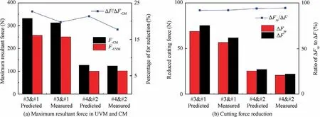
Fig. 13 Comparison and analysis of cutting force in UVM and CM.
where Fis the resultant cutting force of Fand F,ΔFis the amount of reduction of the cutting force F,Fis the resultant cutting force Fin CM,Fis the resultant cutting force Fin UVM.
In Fig.13(b), reduction of the resultant cutting force ΔFand reduction of the resultant cutting force ΔF in CM and UVM is shown.Through the comparison and analysis,it could be found that the amount of reduction of the resultant cutting force ΔFaccounts for more than 90% of reduction of the total resultant cutting force ΔF. It means that the proportion of the cutting force reduced by the inertial force of chip is more than 90%of the total resultant cutting force reduced.It could be concluded that the reason for the cutting force reduced in UVM is the inertial force of chip caused by ultrasonic vibration. Additionally, the contact rate between the cutting tool and workpiece has slight effect on reduction of the cutting force.
As discussion above,it indicates that the acceleration of the chip generated in ultrasonic machining has significant influence on the cutting force,and it is the main reason for cutting force reduction in UVM. Besides, cutting parameters has greatly influence on the inertial force of chip, then it would result in cutting force varying.In Fig. 14,the influence of cutting parameters on the maximum resultant forces F in tests of Table 2 are shown. The results show that the cutting forces in UVM are smaller than that in CM.From Fig.14(a),the maximum reduction of cutting force in UVM is 29.6% when the cutting speed is 21.98 m/min. And with the cutting speed increasing, the magnitude of the reduction is decreased. The reason for this is that the acceleration of the chip is decreased with the cutting speed increasing if the vibration frequency and amplitude is constant. It is noted that when the feed rate is small the cutting force is reduced insignificantly, which is shown in Fig.14(b). It might be that the mass of chip is very small and the inertial effect of the chip is not prominent,which would not lead to an obvious reduction of cutting force, as analysis in Section 3.2.3.From Fig.14(c),the maximum reduction of cutting force in UVM is 31.8%when the cutting depth is 0.2 mm, however, with the cutting depth increasing the reduction of cutting force is decreased.This is because the flow velocity of the chip along the rake face is decreased which will result in reducing of the acceleration of the chip.Therefore,the results show that the acceleration of the chip is the major factor for cutting force reducing.According to the analysis in Sections 3.2 and 4, it could be found from the Eq. (18) that if the acceleration of the chip is reduced to be 0 the ultrasonic vibration-assisted cutting would become conventional cutting.With the acceleration of the chip decreasing the effect of ultrasonic vibration is reduced,which would result in the amount of reduction of cutting force decreasing. Moreover, combining Eqs. (28)and(30), it could be observed that when the acceleration of the chip is reduced the resultant cutting force acted on the rake face of the tool is increased,then the amount of reduction of the cutting force is reduced.
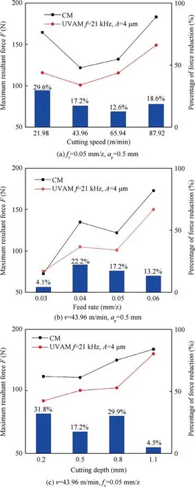
Fig. 14 Maximum resultant force between UVM and CM.
Therefore, it is of importance to take consideration of the effects of the chip acceleration into the cutting force modeling.By comparing of cutting forces between predicted and experimental results, it is proved of great application to predict the cutting force in UVM and CM process.
7. Conclusions
In this paper, a cutting force prediction model was developed to predict the cutting force by analytical method. It was considered the effect of acceleration caused by ultrasonic vibration on the primary cutting zone.And the experiments were carried out to valid the model by milling in-situ TiB/7050Al composites with and without ultrasonic vibration.Based on the results and analysis, following conclusions can be made:
(1) In ultrasonic vibration-assisted cutting, the acceleration of the chip caused by the ultrasonic vibration is needed to take into consideration in cutting force modeling. In this study, the relationship between the acceleration of the chip and the cutting parameters and vibration parameters is developed.
(2) An analytical cutting force model for UVM is performed with considering the effect of the acceleration of the chip,and the force prediction was considered the contact of the tool-workpiece. From the comparison of predicted and measured cutting force,it shows that the predicted cutting force has a good agreement with the measured ones.
(3) The relative error of instantaneous maximum forces between predicted and experimental data of UVM and CM is less than 10% for the forces F, Fand F, but a larger relative error of force component Fis about 10%-15%.On the whole,it is proved that the proposed force model could be used for cutting force prediction with a relative reliability in UVM and CM.
(4) The acceleration of chip caused by ultrasonic vibration is the main reason for the cutting force reduction in UVM.In this study,the cutting force can be reduced by 12%~31% during ultrasonic vibration-assisted milling in-situ TiB/7050Al composites. Besides, vibration parameters and cutting parameters should be properly matched,which is of great importance to reducing cutting force.
In the future study work, the theoretical cutting temperature model will be developed for having a deeper understanding of ultrasonic vibration-assisted machining for in-situ TiB/7050Al composites.
Declaration of Competing Interest
The authors declare that they have no known competing financial interests or personal relationships that could have appeared to influence the work reported in this paper.
Acknowledgement
sThis work is sponsored by National Natural Science Foundation of China (No. 51775443), National Science and Technology Major Project of China (No. 2017-VII-0015-0111).
 CHINESE JOURNAL OF AERONAUTICS2021年4期
- CHINESE JOURNAL OF AERONAUTICS的其它文章
- Time delay compensation in lateral-directional flight control systems at high angles of attack
- Dual stability enhancement mechanisms of axial-slot casing treatment in a high-speed mixed-flow compressor with various tip clearances
- Development cost prediction of general aviation aircraft using combined estimation technique
- Improvement on shaped-hole film cooling effectiveness by integrating upstream sand-dune-shaped ramps
- Modeling and parameter identification of linear time-varying systems based on adaptive chirplet transform under random excitation
- An experimental method to obtain the hard alpha anomaly distribution for titanium alloy aeroengine disks
