Investigation on induction brazing of profiled cBN wheel for grinding of Ti-6Al-4V
Qilin LI, Ki DING, Weining LEI, Jiji CHEN, Qingshn HE,Zhenzhen CHEN
a School of Mechanical Engineering, Jiangsu University of Technology, Changzhou 213001, China
b Nanjing Forestry University, Nanjing 210010, China
c Henan University of Technology, Zhenzhou 450007, China
d Key Laboratory of Special Purpose Equipment and Advanced Processing Technology, Ministry of Education & Zhejiang Province, Zhejiang University of Technology, Hangzhou 310032, China
KEYWORDS Grinding performance;Induction brazing;Profiled cBN wheel;Specific grinding energy;Temperature uniformity
Abstract Profiled monolayer cBN wheel was induction brazed for grinding of titanium dovetail slot in this study.Aimed at acquiring a uniform temperature distribution along the profiled surface and reducing the thermal deformation of the brazed wheel,a finite element model was established to investigate the temperature uniformity during induction brazing. A suitable induction coil and the related working parameters were designed and chosen based on the simulation results. Ag-Cu-Ti alloy and cBN grains were applied in the induction brazing experiment.The results showed geometric deformation of the brazed wheel was no more than 0.01 mm and chemical reaction layer were found on the brazed joint interface. Further validation tests were carried out by grinding of Ti-6Al-4V alloy. Compared to the electroplated wheel, the brazed wheel showed better performance such as low specific grinding energy and good ground quality in grinding of Ti-6Al-4V alloy.Abrasion wear was found to be the main failure mode for the induction brazed wheel,while adhesion and grains pull-out were the main failure mode for the electroplated wheel.
1. Introduction
Titanium alloys are broadly applied as the most common structural metallic material in the aerospace, defense industry and other fields because of their favorable mechanical properties,such as high specific strength and excellent corrosion resistance. However, poor machinability caused by poor thermal properties and high reactivity at high temperatures hinder the manufacturing of titanium alloys parts.High efficiency grinding procedures such as high-speed grinding are developed to meet the machining requirements of these materials.
The cubic boron nitride (cBN) wheels are widely used during high efficiency grinding of titanium alloys.Lately,brazed monolayer cBN wheels were proposed in the grinding of titanium alloys, with the reason that having high bonding strength of grains to matrix, good sharpness, large chipstorage spaces, and long servicing cycle compared to the conventional ones (including electroplated monolayer cBN wheel and multi-layered cBN wheels).Most researchers hold the opinion that a reaction layer formed at filler alloy/cBN grain interface contribute the excellent properties of the brazed cBN wheels. For example, Ghosh and Chattopadhyayfound that a mixture of TiN and TiBgenerated within the reaction layer at cBN-alloy interface,which leading to effective wetting and higher joint strength.
Generally, there are three brazing techniques for the fabrication of brazed cBN wheels, including vacuum furnace brazing,laser brazing,and induction brazing.Comparing to other brazing procedure,induction brazing is more suitable to fabricate the brazed cBN wheels with large size(i.e.,400 mm in diameter),considering that the large wheel could not be brazed in the vacuum resistance furnace because of the limitation of the chamber size. Besides that, with the characters of rapid heating rate and locally heating, induction brazing could decrease thermal deformation of the metallic wheel matrix remarkably.
However, there is a fact in induction brazing that it’s difficult to get a uniform temperature distribution on the wheel surface, especially the profiled wheel. The reason is a phenomenon called‘‘electromagnetic end and edge effects”during induction heating.That means the temperature profiles along the workpiece’s length and width are affected by a distortion of the electromagnetic field in its end and edge areas. Moreover,the electromagnetic field and temperature field are coupled with each other, leading to the induction heating becoming a non-linear procedure. Consequently, finite elemental method(FEM)numerical simulation is used for investigating of induction heating usually. Many studies on the influence factors of temperature filed during induction heating manifested that the structure of the induction coil played a significant role in temperature distribution.For example, Shih et al.investigated the temperature distributions for various coil geometries on a nonplanar mold plate surface subjected to induction heating. The simulation results suggested that the geometry of the inductive coils with respect to the processed workpiece demonstrated a considerable effect on the electromagnetic field distribution and the heating efficiency of the system.Besides that,Li et al.and Gao et al.both believed that the magnetic flux concentrator i.e. magnetizer, had great effect on controlling the surface temperature distribution.However,the curve of the profiled grinding wheel has the characteristic of small curvature radius.Affected by the strong‘‘electromagnetic end and edge effects” during induction brazing, the temperature distribution alone the profile is tendentiously ununiform. The coil design for induction brazing of profiled wheel is a tough work. As a result, investigations related to induction brazing of profiled grinding wheel are very few so far.
In this paper,an induction brazing coil was designed for the profiled grinding wheel. This wheel was used for grinding of a dovetail slot on the titanium blade.The length of the magnetic core of the coil were analyzed by FEM simulation to ensure a proper uniform temperature distribution along the profiled surface of the wheel matrix. Induction brazing experiments were performed on the profiled grinding wheel. The temperature distribution along the width direction and the geometric accuracy for the brazed profiled grinding wheel were monitored.The brazing quality including microstructure characterization of the joining interface and the resultants on brazed cBN grains, was analyzed. Finally, the comparative grinding tests of titanium alloy are conducted with electroplated cBN wheel for investigating the comprehensive performance of the brazed profiled wheel.
2. Modeling and simulation
2.1. Simulation model
Fig. 1 shows the geometry and dimensions of the dovetail slot grinding wheel matrix. The diameter of the wheel is 400 mm.The cross section of the grinding surface is dovetail with small curvature.
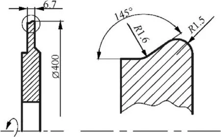
Fig.1 Geometry and dimensions of dovetail slot grinding wheel matrix.
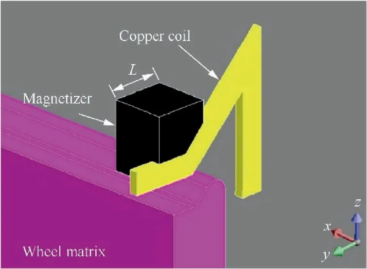
Fig. 2 Simulation model.
In order to investigate the temperature uniformity in induction brazing, a three-dimensional FEM simulation model was built for coil design in this study.Due to the symmetric electromagnetic and temperature field in simulation, the geometry of the model was symmetrical about the YZ planes,and was illustrated in Fig.2(a).The model consists of the wheel matrix,the copper coil, the magnetizer and air domain. The copper coil was set beyond the wheel matrix with cross section size of 2 mm×2.5 mm. Generally speaking, with the characteristic of considerably higher permeability than air and electric conductor,the magnetizer could strongly gather the magnetic flux lines,enhance the efficiency of the heating and acquire the controllable surface temperature.As a result, a magnetizer was employed to enhance the magnetic field intensity near the concave of the wheel surface, considering that the temperature in this area was much lower than that of convexity area of the wheel surface. The convective heat transfer coefficient and the emissivity coefficient of the wheel matrix were defined as 220 W/(m·°C) and 0.8 W/(m·K) respectively. The whole model was set inside the air domain with a constant initial temperature of 20°C. The influence of the magnetizer length (L)on temperature uniformity were investigated in this study.The detailed parameters were shown in Table 1.
2.2. Simulation results
Fig. 3 illustrated the typical temperature counter on the wheel matrix after heating for 5 s with I=26 A and L=2.8 mm.It was obviously that the high temperature concentrated in the surface layer because of the skin effect.The maximum temperature occurred on the concave area of the wheel surface,which should be attributed to the ‘‘electromagnetic end and edge effects”.It implied that under the influence of the proximity effect in the induction heating,the temperature near the end of the workpiece increases more quickly than that of the other area with the same conditions.
In order to evaluate the temperature uniformity of the profiled surface,the uniformity and standard deviation were used.The standard deviation was defined as:

where σ is the standard deviation,Tis the temperature of one measured point on the measure path a to b in Fig. 4, Tis themean of all temperatures in the data set,and n is the total number of measured points.

Table 1 Simulation parameters.
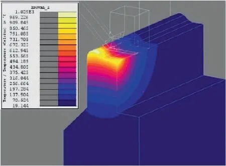
Fig.3 Temperature contour on wheel matrix with I=26 A and L=2.8 mm.
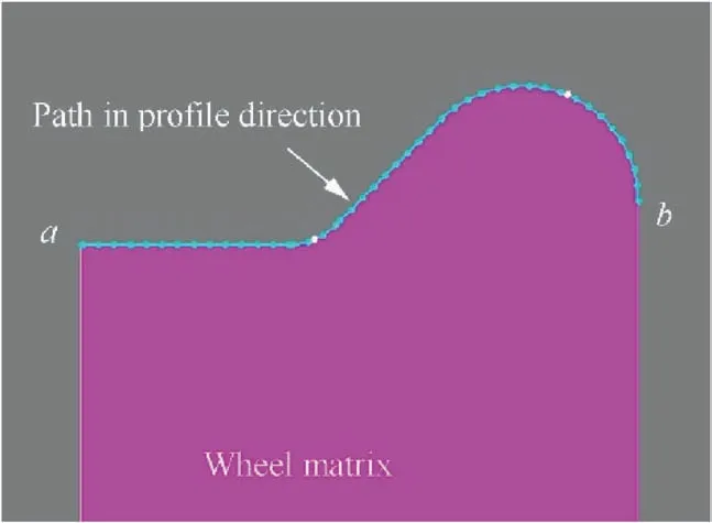
Fig. 4 Measured path for uniformity investigation.
The uniformity was defined as below:

According to Eq. (2), uniformity equals to 1 means a perfect temperature uniformity. In other words, there is no temperature difference among the measured data set.
Fig. 5 showed the temperature uniformity alone measured path from a to b in Fig.4 with different magnetizer length after heating for 5 s. It should be point out that L=0 meant the coil without magnetizer. Fig. 5 demonstrated that the length of magnetizer had great influence on the temperature uniformity of the profiled surface. The temperature uniformity was 77.49%when magnetizer was not applied.With the magnetizer length increasing, the temperature uniformity was increasing first and then decreasing. The highest uniformity was 95.41%when L=2.8 mm in this study.
2.3. Verification of the simulation result
An experimental setup was established to verify the simulation results as shown in Fig. 6(a). The coil was designed according to the simulation result with the magnetizer length of 2.8 mm.The infrared (IR) thermography was employed to obtain the temperature distribution on the profiled surface of wheel matrix. The emissivity of the workpiece was set to 0.8.
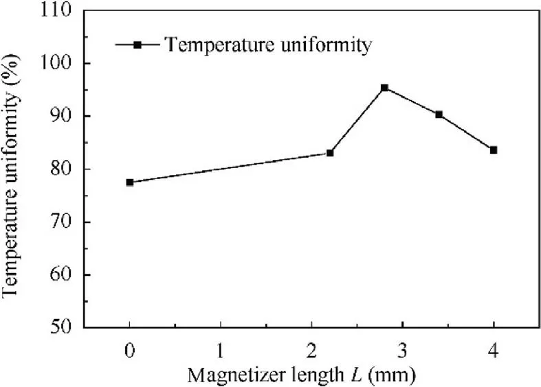
Fig. 5 Temperature uniformity alone measure path with different magnetizer length.
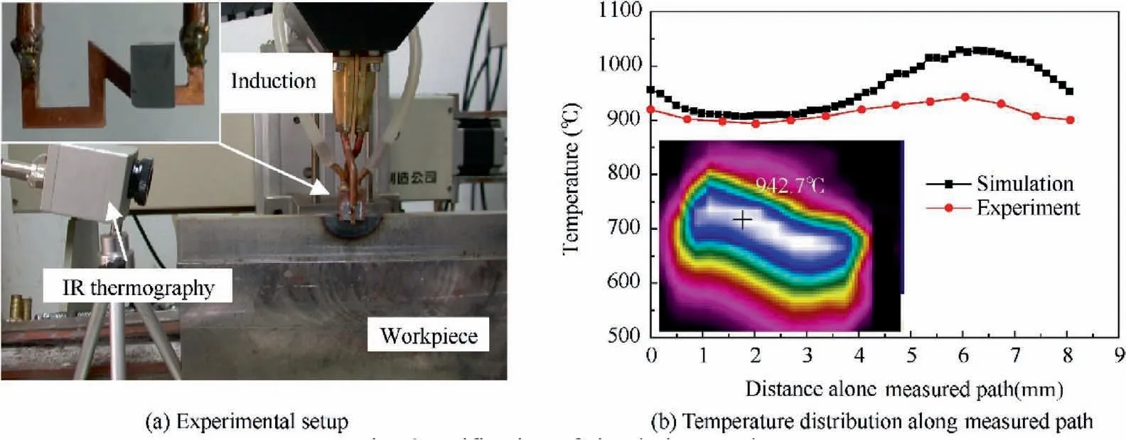
Fig. 6 Verification of simulation result.
Fig. 6(b) showed the comparison of the temperature distributions between the simulation result and the experiment with the induction current I=26 A for 5 s. The x axis in Fig. 6(b)meant the distance from point a along the measured path in Fig.4.It was demonstrated in Fig.6b that the temperature distribution in experiment and simulation with a range of 893.7-942.7°C and 906.8-1029.8°C respectively. The uniformity of the experimental result and simulation result was 98.19%and 95.41% respectively. It was noticed that the maximum temperature in experiment was 9.24%less than that of simulation result. This may be attributed to the heat loss to the surroundings during the brazing process.
3. Induction brazing experiments
3.1. Fabrication of brazed profiled cBN wheel
The cBN grains with average size ranged from 150 to 180 μm,were arranged orderly on the wheel matrix. The wheel matrix was ANSI 1045 steel. The (AgCu)Timixed powder was used as the brazing alloy. The brazing of profiled wheel was carried out on the special platform as that of in previous research.The schematic diagram was illustrated in Fig. 7.The designed induction coil which connected to the high frequency(f=1 MHz)power source,was placed upon the wheel.The gap between the coil and wheel was 2 mm. During brazing,the wheel counterclockwise rotated within a linear velocity of 1 mm/s. The induction power was about 6 kW to ensure that the maximum temperature of the molten pool was about 940°C.Argon with a flow rate of 40 L/min was applied to protect the brazed surface from being oxidized.
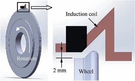
Fig. 7 Schematic diagram of induction brazing.
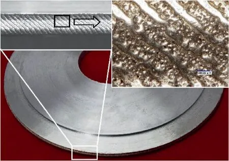
Fig. 8 Morphology of induction brazed profiled wheel.
Fig.8 showed the morphology of induction brazed profiled wheel. A consistent quality seems to be obtained on the wheel surface. Besides that, the brazing alloy spread out uniformly on the wheel surface. The cBN grains had good exposure altitude both on the concave and convexity area of the wheel surface. This should be attributed to the good temperature uniformity during induction brazing.
3.2. Geometric accuracy
During the induction brazing, the rapid heating and cooling could cause phase transformation and thermal plastic deformation in the surface of brazed wheel, leading to the decreasing of the wheel geometric accuracy.In order to investigate the deformation of the brazed profiled wheel,the dimension of the wheel matrix was measured both before and after brazing by coordinate measuring machine(Micro-Hite DCC).The geometry subjects to be measured (including the end surface C, the cylindrical surface D and the inner hole A) were shown in Fig. 9(a).
It could be seen from the measured results demonstrated in Fig. 9(b) that all the geometric dimension of the brazed profiled wheel increased a little after brazing.Even so,all of them were no more than 0.02 mm,which met the requirement of the designed accuracy. Additionally, the deformation, which was defined as the difference between the dimensions before and after brazing, was below 0.01 mm. This should be attributed to the rapid local heating during induction brazing procedure.Therefore, induction brazing was an excellent method to control the deformation of the wheel.
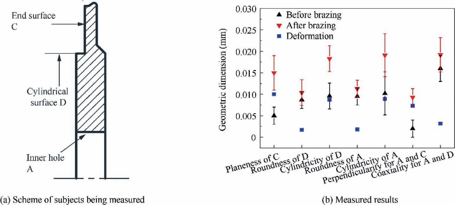
Fig. 9 Geometric accuracy of brazed profiled wheel.
3.3. Microstructure characterization of joining interface
Fig. 10(a) demonstrated the representative metallographic structure morphology of the brazed joint. Due to the short processing time in brazing procedure, the small grain α-Ag solid solution formed in the brazing alloy layer. The fine and small grain size in the brazing alloy had the strengthen effect to the brazed joint, which was benefit for prompting the performance of the brazed wheel. Fig. 10(b) illustrated the corresponding element distribution taken by EDX along the white line in Fig. 10(a). From the element distribution curves, it could be seen that the Ti element was dramatically transferred towards and concentrated both on the interface of matrix/Ag-Cu-Ti alloy and Ag-Cu-Ti alloy /cBN grain. Moreover, at interface I (i.e. the interface of matrix/Ag-Cu-Ti alloy), a Ti-Fe intermetallic interlayer was developed,indicating good wetting between Ag-Cu-Ti alloy and wheel matrix. Interface II(i.e. the interface of Ag-Cu-Ti alloy /cBN grain) was enriched in element Ti, N and B. The higher Ti concentration in the vicinity of the cBN grain surface implies that Ti from the Ag-Cu-Ti alloy has actually segregated. This phenomenon was consistent with the high chemical affinity of element Ti towards B and N, indicating that chemical reaction could be likely to take place at interface II.
Fig. 11 showed the SEM micrograph of the microstructure of the newly formed compounds on the surface of cBN grains after electrolysis treatment with vol.10 % HNO. Obviously,this corresponds to the interface of Ag-Cu-Ti alloy/cBN grain in Fig. 10. It implied that a good brazing bond between Ag-Cu-Ti alloy and cBN grains was achieved.The graininess compounds A and the needle-like compounds B covered on the surface of the cBN grain. The diameter of both compounds A and B was less than 200 nm.
Many of the researchers such as Johari MR believed that the brazing mechanism of Ag-Cu-Ti alloy and cBN grains could be attributed to the preferential migration effect of active element Ti on the surface of cBN grain crystal to generate TiN and TiB.The follow reaction could occur when brazing temperature was over 807°C:

The crystal structure of TiN was face centered cubic structure with lattice constant of 0.4235 nm. The morphology of TiN formed in reaction was graininess usually.As the stable compound between element Ti and B, TiBwas the C32-type metalloid compound in hexagonal system. Generally, TiBgrew along [0001] and <1100>crystal orientation during the reaction, leading to TiBcrystal appear columnar or needle-like morphological structure.As a result,according to the morphology in Fig.11,the compounds A and B should be TiN and TiBrespectively.
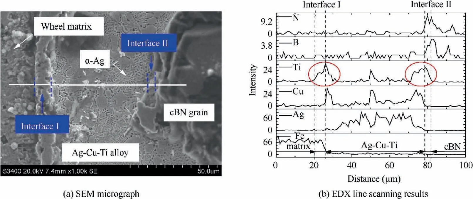
Fig. 10 Brazed joint interface of wheel matrix/Ag-Cu-Ti alloy/cBN grain.
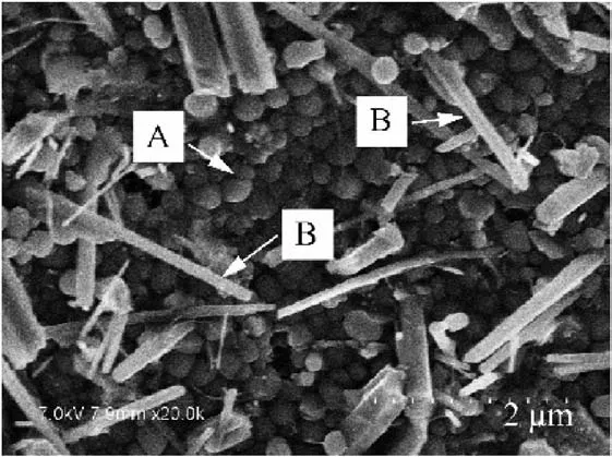
Fig. 11 SEM micrograph of microstructure of newly formed compounds on surface of cBN grains.
4. Grinding performance of the brazed profiled wheel
4.1. Grinding parameters
The grinding experiments for Ti-6Al-4V alloy was carried out in a high-speed grinding machine BLOHM Profimat MT408.A 5% solution of a soluble water-based coolant was used as the grinding fluid. The comparative tests were conducted with electroplated cBN wheel for investigating the ground surface quality. Grinding parameters were displayed detailly in Table 2.
4.2. Results and discussion
4.2.1. Dimensional accuracy of the ground profiled slot
The typical ground profiled slot was illustrated in Fig.12 with the grinding petameters of ν=80 m/s, ν=240 mm/s and a=0.3 mm. Three specimens (located in entrance, middle and departure of the slot respectively) were prepared for the dimensional accuracy investigation on the measuring microscopes, and the results were showed in Table 3. The measured subjects were radius of the two arcs and angle between the top and slope. As illustrated in Table 3, the minimum and maximum values of the measured dimensions were all accordance with the designed values.
During profiled grinding, the wheel wear affected significantly the shape and accuracy of the ground slot. Generally speaking, the wheel wear at out corner was faster than other areas,considering that the liquid coolant was difficult to enter into this area leading to the worse friction wear.It was noticed that the tolerance of the radius of curvature R2 was closed to the upper limit of the designed value in this study. This could balance the wear speed of each profiled areas on the brazed wheel, and was useful for maintaining the shape and accuracy of the ground slot in grinding.

Table 2 Grinding parameters.
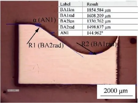
Fig. 12 Cross section morphology of ground slot and dimensional measuring scheme.

Table 3 dimensions of the ground profiled slot.
4.2.2. Specific grinding energy
The specific grinding energy which was a crucial characteristic in the grinding process, was applied to investigate the performance of the brazed profiled wheel. The specific grinding energy ewas defined as the rate of energy consumption divided by the material removal rate, and was expressed as:

where Pis the net grinding power,Qthe volumetric removal rate,Fthe tangential force,vthe grinding wheel speed,vthe feed rate, athe cutting depth, and b the width of wheel, i.e.6.7 mm in this study.
The grinding result of the specific grinding energy versus the specific material removal rate Qmm/(mm/s)) was plotted in Fig.13.It was observed that the grinding specific grinding energy decreases with the increase of the specific material removal rate. Moreover, with the same material removal rate,the specific grinding energy of the brazed wheel was much lower than that of electroplated ones. This indicated that the brazed wheel was superior in energy consumption during grinding. It was mainly attributed to the sufficient chip capacity and sharp cutting edges on the brazed wheel surface,which required less energy to remove the material and avoid the chip adhesion.
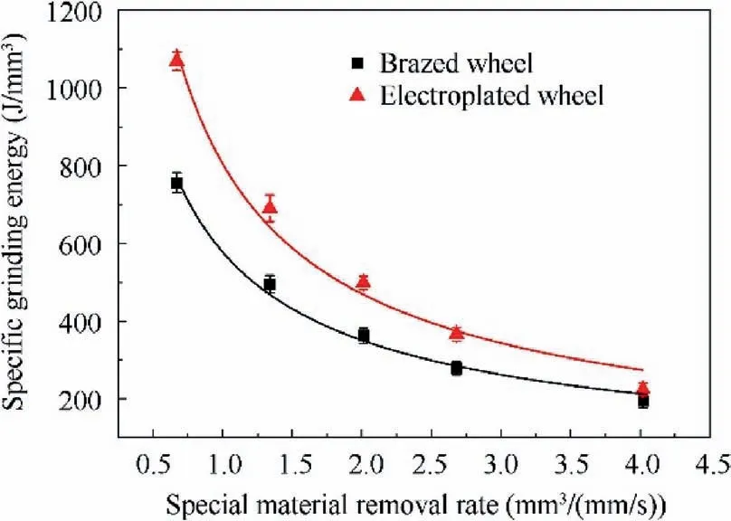
Fig.13 Specific grinding energy plotted versus material removal rate.
4.2.3. Microstructure of the ground profiled slot
Fig. 14 illustrated the microstructure of the ground profiled slot.It was obviously in Fig.14(a)that the microstructure near the ground surface remained consistent with that of the bulk material, which consisted of typical bimodal microstructure with original α phase and fine β phase. While the grain was stretched along the grinding direction near the ground surface when electroplated wheel was applied, and was shown in Fig. 14(b). It could be observed that the depth of stretched layer was about 20 μm. It could be seen from the results in Fig. 12 that the specific grinding energy of the electroplated wheel was much higher than that of brazed wheel. According to Eq. (4), this indicated that the grinding force was much higher, leading to the high risk of grain stretching when electroplated wheel was applied.
4.2.4. Wheel surface morphology after grinding
Generally speaking, the grinding performance of a wheel directly depends on the cutting ability of grains on its surface.With regard to cutting ability, all grains with states of whole,abrasion, and micro-fracture can be regarded as strong grains since they still have cutting abilities.As a result, the quality of surface morphology can reflect the condition of a grinding wheel. Fig. 15 illustrated the typical surface morphology of the two types of wheels observed by microscope when the specific material removal volume reached up to 2000 mm/mm. It should be noticed that both two wheels were on their duty cycle, i.e. having cutting ability yet. it was evidently that inter-grit spaces of the brazed wheel were much larger than that of electroplated count part. The abrasion flat of the cBN grains was dominant on the brazed wheel surface as in Fig. 15(a), while micro-fracture could be also observed. No crash or pull-out of the grains occurred.By contrast,the adhesion and grains pull-out were found to be dominant on the electroplated wheel surface as in Fig.15(b),while abrasion flat of the cBN grains could be also observed infrequently. Grinding debris adhered to the surface of the electroplated wheel and made it blunt, which attributed to the higher grinding force and temperatures. This was in accordance with the results in Figs. 13 and 14. Besides that, poor bonding strength between cBN grains and matrix of electroplated wheel result in the grains pull-out more easily.Above all,that’s to say,the brazed cBN wheel was superior than electroplated cBN wheel in grinding of Ti-6Al-4V alloy.
5. Conclusions
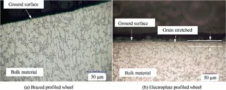
Fig. 14 Microstructure of slot ground by brazed profiled wheel and electroplate profiled wheel.
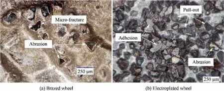
Fig. 15 Typical wear morphology of brazed wheel and electroplated wheel.
(1) A simulation model was established for the designing of coil in induction brazing of profiled wheel. Simulation results illustrated that the length of magnetizer had great influence on the temperature uniformity of the profiled surface.With the magnetizer length increasing, the temperature uniformity was increasing first and then decreasing. The coil with magnetizer length of 2.8 mm had the optimal uniformity of 95.41% in this study.The comparison of the temperature distributions between the simulation result and the experiment showed good accordance with each other. The uniformity of the experimental result was 98.19%, which was better than that of in simulation.
(2) The fabrication of profiled cBN wheel was carried out with induction brazing. The chemical compounds were found on the surface of cBN grains, indicating a good bond between brazing alloy and cBN grains. The cBN grains had good exposure altitude both on the concave and convexity area of the wheel surface.All the geometric dimensions of the brazed profiled wheel were no more than 0.02 mm, which met the requirement of the designed accuracy. Additionally, the deformation of the brazed wheel was below 0.01 mm.
(3) The grinding tests for Ti-6Al-4V alloy illustrated that the ground slot had good profiled accuracy with the developed brazed profiled wheel. Compared to the electroplated wheel, the brazed wheel showed better performance such as low specific grinding energy and good ground quality in grinding of Ti-6Al-4V alloy.Abrasion wear was found to be the main failure mode for the induction brazed grinding wheel, while adhesion and grains pull-out were the main failure mode for the electroplated wheel.
Declaration of Competing Interest
The authors declare that they have no known competing financial interests or personal relationships that could have appeared to influence the work reported in this paper.
Acknowledgement
The authors are grateful to the anonymous reviewers for their critical and constructive review of the manuscript. This study was supported by the National Natural Science Foundation of China (Nos. 51905234, 51805231, 51975264, 51905275,51705463).
 CHINESE JOURNAL OF AERONAUTICS2021年4期
- CHINESE JOURNAL OF AERONAUTICS的其它文章
- Time delay compensation in lateral-directional flight control systems at high angles of attack
- Dual stability enhancement mechanisms of axial-slot casing treatment in a high-speed mixed-flow compressor with various tip clearances
- Development cost prediction of general aviation aircraft using combined estimation technique
- Improvement on shaped-hole film cooling effectiveness by integrating upstream sand-dune-shaped ramps
- Modeling and parameter identification of linear time-varying systems based on adaptive chirplet transform under random excitation
- An experimental method to obtain the hard alpha anomaly distribution for titanium alloy aeroengine disks
