
Pressure relief of underground ammunition storage under missile accidental ignition
2021-05-06 12:30:42weiWngYuzhuoYngGownZouHuiDongYnHuo
Defence Technology 2021年3期
Y-wei Wng ,Yu-zhuo Yng ,Go-wn Zou ,*,Hui Dong ,Yn Huo
a College of Aerospace and Civil Engineering,Harbin Engineering University,Harbin,Heilongjiang,China
b Architecture and Civil Engineering Department,City University of Hong Kong,Hong Kong,China
Keywords:Underground ammunition storage Pressure relief Large-scale experiment Missile accidental ignition
ABSTRACT Safety of underground ammunition storage is an important issue,especially during the accidental ignition of missiles.This work investigates the pressure and temperature distribution of the multi-layer underground ammunition storage with a pressure relief duct during the accidental ignition process of the missile.A large-scale experiment was carried out using a multi-layered restricted space with a pressure relief duct to simulate the underground ammunition store and a solid rocket motor to simulate the accidental ignition of the missile.The results show that when the motor gas mass flow increased by 5.6 times,the maximum pressure of the ammunition storage increased by 5.87 times.At a certain motor flow rate,when the pressure relief exhaust area at the end of the relief duct was reduced by 1/2,the maximum pressure on the first layer did not change.But the rate of pressure relief was reduced and the time delayed for the pressure of ammunition store to drop to zero.In this experiment,when the motor ignition position was located in to the third layer ammunition chamber,the maximum pressure was reduced by 32.9% and also reduced the rate of change of pressure.In addition,for the experimental conditions,the theoretical analysis of the pressure relief of the ammunition storage is given by a simplified model.Based on the findings,some suggestions to the safety protection design of ammunition store are proposed.
1.Introduction
Due to explosive risks,some ammunition must be stored underground.However,the resulting damage caused by ammunition storage fires is of rising concern.The accidental ignition of missiles is especially dangerous[1].Due to the propellants being extremely sensitive to external thermal and electrostatic stimulations.When a propellant’s temperature reaches a certain level or generates an electrostatic discharge,phenomena such as self-ignition or explosions may occur[2].These phenomena may damage the structure of the ammunition store,making the warhead and other missiles prone to thermally induced firing(ie cooking off),causing the ammunition to explode,thereby resulting in a wider range of damage.As of late,accidents such as this have occurred with frequency.For example,in March 2012,ammunition storage exploded in a city in Congo,causing 206 deaths and thousands of injuries.In February 2011,ammunition at a military base in the capital of Tanzania exploded.Additionally,a major accident,known as the Nigerian national disaster,was caused by a series of explosions in an ammunition store,resulting in at least 2000 deaths[3].It has been reported that these accidents,of which there are many,may be due to the spontaneous combustion of ammunition caused by high temperatures.Therefore,safely designing ammunition storage to prevent the accidental ignition of missiles is very important.
Solid propellants are the main power source of rocket motors.Approximately 85% of the missiles in use worldwide are solid rocket motors[4].Solid rocket motors are powerful missile devices that continuously increase the energy requirements of composite propellants with the rapid development of high technology.The high energy of solid propellants significantly reduces the thermal safety of rocket motors during transportation,storage,and use,increasing their risk[5].In 1969 and 1981,the US Navy’s enterprise and Nimitz aircraft carriers,respectively,suffered from missile solid propellant safety accidents[6]that resulted in significant personnel and equipment losses.On January 11,1985,the US military were conducting“Pershing”II missile assembly training at a base near Hailblung,former West Germany when the solid rocket motor caught fire and exploded[7].In the early stage of missile launching,the rocket engine burns completely to produce a large number of high-temperature and high-pressure gases.Then,oxygen in the air is entrained in the chamber,and a secondary combustion of the gas in the ammunition storage occurs,producing a strong,infrared radiation tail flame[8,9].As an ammunition store is a closed space,its temperature and pressure increases rapidly causing missiles in storage to bake.
Among the protective technical measures of ammunition stores,pressure relief is one of the most important[10].In the case of unexpected motor ignition,when the pressure of the ammunition store reaches a set value,the pressure relief device installed will open quickly to allow the high-temperature and high-pressure gas to exit.Zhang et al.simulated ammunition stores with different fire sources and mastered the characteristics of the accidental ignition fire of a missile in ammunition storages[11].Li et al.performed a numerical simulation on the flow field of spray cooling in ammunition storage after the accidental ignition of a solid rocket motor[12].According to the equations of conservation of energy and mass,they established a differential equation for the exhaust process of the ammunition store after the accidental ignition of the missile in storage.The exhaust process is calculated when the missile is accidentally ignited in the ammunition store.Based on this,the differential equation of the exhaust process when spraying an inhibitor after accidental ignition of missiles is established,and the influence of the spraying inhibitor is studied[13,14].N.Davis et al.calculated pressurization rates versus time for different magazine confinement/energetic material reaction rate combinations to determine its effect on magazine structures by simulating the pressure rise inside an earth-covered magazine from the burning of solid gun propellant[15].In the existing research on the accidental explosion of underground ammunition storage,studies have focused on earthquake disasters,debris disasters,and structural damage caused by ammunition explosions[16-21].However,research is lacking on the variation law of the pressure and temperature fields in the ammunition store and pressure relief when the missile is accidentally ignited.Nevertheless,there is some research that is relevant to solid rocket motor ignition in confined spaces.Lunn et al.investigated the effects of vent ducts on reduced explosion pressure,derived a simple model to describe the effect of vent ducts on the reduced explosion pressure,and compared with the experimental results[22].Gao et al.investigated propane refrigerant explosion leakage in a square model chamber under different venting conditions and determined the relationship between the concentration of combustible gas before ignition and the transient temperature and pressure after ignition[23].Chow et al.numerically studied the pressure rising in closed chamber fires[24].
Among the existing safety regulations related to various types of ammunition storage,there are no specific regulations to ensure that when accidents under the normal level occur(one or two missile motors are accidentally ignited),the ammunition storage has the ability to discharge high-temperature gas in a timely manner,without further expanding the damage.Thus,guidelines for how to design the discharge capacity of the gas stream and how to determine the size of the vent are critical in the design of the ammunition storage.However,there is little published literature for design reference.
This study aims to investigate the influence of the accidental ignition of missiles on the space environment of underground ammunition storage,specifically regarding temperature and pressure changes before and after opening the pressure relief device,in order to develop reliable guidelines to safely design underground ammunition storage.This experiment simulates underground ammunition store with a multi-layered and large restricted space with a pressure relief duct and uses a solid rocket motor to simulate the accidental ignition of a missile.Different working conditions were used to investigate the main factors influencing the pressure relief process.Based on the results of this experiment,a theoretical calculation method for the pressure release of the ammunition storage was developed.This calculation method can be used to guide pressure relief designs of ammunition storage in the case of accidental ignition of missiles,thereby increasing the safety of ammunition storage.
2.Methods and materials
When an accidental explosion occurs,the underground space can only be relieved to the outside through a relief duct or ventilation passage[25].However,the presence of ducts severely increases the severity of explosions,posing problems for the proper design of ventilation devices[26-28].In prior studies,the experimental model has mostly been a single,confined space with a venting window or relief duct,and the structure is relatively simple.Underground ammunition storage usually has more than one chamber.Therefore,in this study,we used a limited space structure,which is a design in which multiple layers of the internal chamber are connected to the same relief duct.It is also of great significance to be safe while studying underground dangerous goods storage.
2.1.Experimental ammunition storage model
The large model ammunition storage used for this experiment consisted of a three-layer storage space and an exhaust pressure relief duct,as shown in Fig.1.The ammunition storage model is an irregular structure made of welded steel.The solid rocket motor was placed on the test bench inside the ammunition storage model.
The model of the underground ammunition store used in this test was simplified from actual ammunition storage,retaining only the general size and spatial structure,and ignored some of the detailed design.The test model has a first layer of 84 m3and other two layers of 126 m3,wherein each layer has a height of 2.5 m.The area of the relief window connecting the space of each layer to the relief duct is 0.5 m2.The test model can reach a pressure of 0.2 MPa without measurable leakage.
2.2.Solid rocket motor
This study uses two typical models of solid rocket motors:type A and type B.Both types of motor propellants were selected from a three-component composite propellant,and the gas mass flow rate remained unchanged during the working process.The solid rocket motor parameters used in the test were redesigned according to the relationship between the parameters of a prototype missile engine and the volume of the ammunition storage.The method used to induce the accidental ignition of missiles was not considered in this study.The ignition mode was a regular charge ignition.The motor parameters are listed in Table 1.
2.3.Ammunition storage pressure relief device
At the outlet of the pressure relief duct of the ammunition storage model,there are four pressure relief exhaust ports.The opening and closing of the pressure relief duct is achieved by controlling the movement of the exhaust cover.The exhaust cover size in this experiment is 305 mm×305 mm,and the net exhaust area is 0.0909 m2,as shown in Fig.2.The exhaust cover opening response time is no more than 1 ms,and the exhaust cover opening pressure is no more than 8 kPa.The maximum angle of the exhaust cover opening exceeds 90°.Herein,the tightness of the pressure relief device and actuation speed were examined.
Fig.1.Model ammunition storage.
Table 1Solid fuel rocket parameters.
2.4.Pressure sensor arrangement
Only two pressure sensors are in each layer of the ammunition chamber.One is located in the center of the side wall of each layer,named PRC,and the other is positioned in the same wall but adjacent to the relief window,named PO,as shown in Fig.3(a).In the pressure relief duct,the pressure measuring points are arranged along the duct,starting from the bottom of the pressure relief duct to the outlet,referred to as PC.The pressure sensors are arranged at the center line of the side wall on the same side as the duct,and all the pressure measurements are by wall tappings,as shown in Fig.3(b)and Fig.4.A total of 16 pressure points are included in this experiment.The specifications of the pressure sensor are as follows:
Range:≤0.25 MPa;
Accuracy:±0.5% FS;
Response frequency:1 kHz.
2.5.Temperature thermocouple arrangement
A total of 26 temperature measuring points were included in the experiment.A section of the temperature measuring point arrangement is shown in Fig.3(c).Four temperature measuring points are arranged at different heights on the same vertical line at the pressure relief window of each ammunition layer,herein referred to as TR.The temperature measurement point(denoted as TRC,TC)arrangement is consistent with the pressure measurement point(PRC,PC)arrangement.Each temperature measuring point is 0.25 m from the wall surface of the ammunition chamber.In addition,outside the ammunition storage model,a temperature measuring point is located at the center of the side wall of the first layer to measure the temperature rise of the wall surface.Because of the fast flow rate of high temperature gas,the S-type thermocouple with bare measuring end is used for temperature measurement.In order to protect the thermocouple from being ablated by the high-temperature gas stream,a ceramic material is used to protect and support the thermocouple wire.Owing to the high brittleness of the ceramic and the extensive vibration generated by the test,a stainless-steel tube was placed around the ceramic for further protection.The specification parameters of thethermocouple are as follows:
Fig.2.Pressure relief device.
Model:S
Range:0-1600°C
Accuracy:±0.25%t(tis the measured temperature)
Response time:<0.1 s
2.6.Gas flow velocity measurement
A pitot tube was used for velocity measurements to monitor the dynamic pressure of the velocity flow in and out of the exhaust cover.Two pitot tubes,directed inwards and outwards,were arranged at the center of the opening of the exhaust cover to monitor the airflow in and out of the exhaust ports(see Fig.5).
2.7.Experimental conditions
The experiment was divided into four groups,as summarized in Table 2.The first group used the type A motor,while the other three groups used the type B motor.The pressure and temperature changes of the ammunition storage under various workingconditions were measured.The effects of gas flow,exhaust port area,and motor working position on the exhaust pressure of the ammunition storage were studied for each group.
Fig.5.Installation diagram of two pitot tube measurement points.

Table 2Experimental conditions table.
3.Results and discussion
3.1.Variation of parameters in the pressure relief process
Fig.6 shows the pressure changes in test-1,wherein(a)and(b)show the gas pressure curves measured at the PO and PRC measuring points of each layer of ammunition in this working condition,respectively.The pressure of the first layer ammunition chamber reached a maximum value of 0.0201 MPa approximately 0.64 s after motor ignition.The pressure of the second layer ammunition chamber was approximately 0.0118 MPa at a time of approximately 0.92 s.The maximum pressure of the third layer of ammunition storage was approximately 0.0115 MPa at 1.26 s.The pressure at the measuring point PO almost coincides with the pressure curve at the measuring point PRC,showing that the pressure inside each layer of ammunition storage is relatively uniform.
The gray horizontal solid lines in Fig.6(a)and(b)indicate the external ambient air pressure.Because of the measurement error of the sensor and the curve smoothing method that was used,there were small negative pressures in the P02 and PRC-1 readings prior to ignition(-2 s-0 s).After the motor finished,the minimum pressure inside the model ammunition store was lower than the external ambient air pressure.The reason for this phenomenon is attributed to the heat dissipation effect of the steel structure,which causes the internal gas temperature to drop,making the air in the ammunition storage shrink.This results in an internal pressure that is lower than the ambient air pressure.As shown in Fig.7(a),because the temperature of the gas in the first layer of the store is the highest,the density changing of gas in that layer is the most.Meanwhile,because the distance between the first layer of ammunition storage and the exhaust ports is the farthest,the first layer of the store has the largest negative pressure value,followed by the second layer,and then the third.
Fig.6(c)shows that the pressure values from PC1 to PC9,measured from the motor,along the relief duct,to the outside of the exhaust ports,gradually decreased.This is in accordance with the gas flow law.All the measured points had negative pressure after motor operation ceased.The closer to the exhaust ports the measurement was taken,the smaller the negative pressure.Because the PC10 measuring point is located outside the exhaust ports,the monitored value at PC10 was closer to the ambient air pressure,making the overall pressure change small.The cross-sectional area of the relief duct between the measuring points PC2 and PC3 decreases and the relief duct has a 90°turning point,causing the airflow pressure to significantly reduce.The pressure drop between the PC9 and PC10 measuring points is also large,and the pressure of the airflow experiences a large change as a result of the sudden area limitation of the exhaust ports.
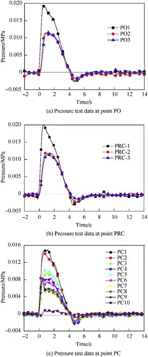
Fig.6.Pressure test results during test-1.
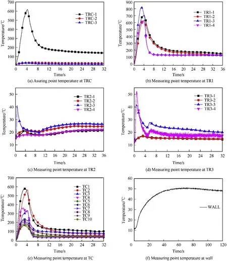
Fig.7.Temperature test results in test-1.
Because the pressure measuring point PC9 is positioned closest to the inside of the exhaust cover,when the exhaust cover is closed,the pressure inside the exhaust cover can be considered to be equal to the pressure at PC9.As shown in Fig.6(c),after the motor starts working,the pressure at the exhaust cover rises rapidly.At approximately 0.37 s,the pressure inside the exhaust cover reaches an alarm pressure of 8 kPa,triggering the exhaust cover to open.After the exhaust cover opens,there is a significant drop in the pressure at PC9.
Fig.7 shows the temperature change at each temperature measurement point under test-1 conditions.Fig.7(a)shows that the maximum temperature at TRC-1 is 617.6°C.In the test,this peak appears at the end of the motor operation,which is later than the peak pressure.Limited by the flow velocity of the airflow and the structure of the ammunition,there is a large temperature difference between the different ammunition chambers.When the solid rocket motor finishes operation,the temperature of the first layer of ammunition storage rapidly decreased,and the internal temperature of the store gradually became balanced.There are two main reasons for the temperature drop in the ammunition store.One is the loss of heat caused by the heat through the store wall.The other main reason is the low temperature gas recirculation caused by the negative pressure in the ammunition storage.
It can be seen from Fig.7(b)that although the TR1-1 to TR1-4 measuring points are inside the same ammunition chamber,their temperature changes varied significantly as a result of their different height positions.This indicates that the temperature inside the ammunition chamber is not uniform.In addition,the rate of temperature drop of the measuring points TR1-3 and TR1-4 is significantly faster than that of measuring points TR1-1 and TR1-2.This is because TR1-3 and TR1-4 are located at the relief window of the ammunition chamber connected to the duct.Thus,the returning airflow passes through here first,causing the gas temperature at this position to drop rapidly.In Fig.7(c)and(d),the temperature changes of TR2-3,TR3-3,and TR3-4 are also significantly different from the other measuring points as they are affected by the airflow direction in the pressure relief window of the ammunition chamber.
Fig.7(e)shows the temperature changes at different measuring points inside the relief duct under test-1 conditions.Note that the temperature rises later at measuring points located nearer to the exit of the duct because the high temperature gas arrives later at those points.Meanwhile,more cold air mixes with the hightemperature gas,causing a lower maximum temperature change near the exhaust ports.For the motor-generated high-temperature gas to enter the second and third layers of the ammunition chamber,it must pass through the duct and then mix with the air in the two-layer ammunition chamber to cool down.Therefore,the temperature of the gas in the duct is higher than the temperature of the gas in the two ammunition chambers.
The all-steel structure of the model ammunition storage affects the temperature of the gas inside the ammunition storage.Fig.7(f)shows the temperature rise of the wall in the first layer of model ammunition storage during testing.The wall temperature of the ammunition chamber correlates with the gas cooling inside the ammunition chamber.Fig.7(a)shows that 4-10 s is the fastest gas temperature drop in the ammunition storage and temperature rise on the outer wall of the ammunition storage.The heat transfer effect through the wall of the store is the main cause of the drop in the gas temperature inside the ammunition storage.In this test,the peak temperature rise of the outer wall of the first-layer ammunition store was 50.4°C.
Fig.8 shows the pitot tube measurements.Because of the characteristics of the pitot tube,the negative part of the curve in the figure is meaningless.As can be seen from Fig.8,when the exhaust cover is opened,the outflow speed at the exhaust port rises rapidly.After the pressure in the ammunition chamber reaches a maximum value,the gas outflow dynamic pressure value at the exhaust port also reaches its maximum.Subsequently,the gas outflow dynamic pressure value decreases with decreasing ammunition chamber pressure.When the speed at which the ammunition chamber gas flows to the outside drops to zero,the velocity at which the airflow at the exhaust port flows into the ammunition chamber begins to rise.At this moment,gases from the external environment begin to flow into the ammunition chamber.The dynamic pressure monitoring value of the airflow proves the aforementioned theory of reverse flow.
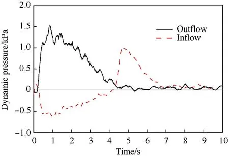
Fig.8.Airflow dynamic pressure at the exhaust port.
3.2.Influences of the factors on pressure during pressure relief
Test-2 had a larger increase in motor mass flow than test-1.As can be seen from Fig.9(a),the pressure of the ammunition chamber is much higher than that in test-1 as a result of the large increase in the gas mass flow of the motor.The pressure difference between the three-layer ammunition chamber is similar to that of test-1.The maximum possible pressure of the ammunition chamber was 0.118 MPa,which is 5.87 times greater than the maximum pressure of test-1,which was 0.0201 MPa.The pressure curve of the first layer of the ammunition chamber in test-2 reached a maximum at approximately 0.8 s.Further,in test-2,the pressure change rate of the first layer of the ammunition chamber is larger.The pressure of the first layer of the ammunition chamber changes more dramatically than that of the second third layers.Moreover,the time at which the pressure reaches its maximum value is later than that of the first layer of the ammunition chamber,and the speed of the pressure drop is relatively slow.After the motor has finished working,the pressure of each layer is relatively close.The pressure change law of each pressure measuring point in the relief duct shown in Fig.9(b)is the same as that of test-1.However,the exhaust cover opened at approximately 0.12 s,which was 70%earlier than in test-1.
In test-2,the negative pressure value in the ammunition chamber after the end of motor operation is smaller than that in test-1,and the negative pressure phenomenon is relatively weak.According to Fig.10,at the end of motor operation,the first layer pressure remains a large positive value.Then,when the pressure of the ammunition chamber drops to 0,the velocity of the gas temperature drop in the ammunition chamber greatly reduces,and the gas temperature begins to stabilize.As the stability of the gas temperature causes the driving force of negative pressure in the ammunition chamber to disappear,the negative pressure of the ammunition chamber is smaller under test-2 conditions.
The trend of the data collected in test-3 is basically the same as that in test-2.Fig.11 shows that under both working conditions,the internal pressure change law of the ammunition chamber is similar.In each test,the maximum pressures reached in the first layer of the ammunition chamber were very close.However,after reaching these maximum values,the pressure drop rates inside the ammunition chamber were different.The area of the exhaust ports in test-3 is smaller than that in test-2.Thus,the pressure drop in the ammunition chamber is smaller.In test-3,the pressure of the first layer of the ammunition chamber reached a maximum of 0.119 MPa at 0.83 s.The pressure of the second layer reached a maximum of 0.073 MPa at 1.76 s,and the third layer reached a maximum pressure of 0.072 MPa at 1.92 s.Conversely,in test-2,the pressure of the second layer of the ammunition chamber reached a maximum value of 0.056 MPa at 1.38 s,and that of the third layer was 0.0545 MPa at 1.56 s.Compared with test-2,the maximum pressure of the second and third layers of the ammunition chamber increased significantly in test-3.In test-2,the internal pressure of the ammunition storage was the same as the external pressure,and occurred 7.15 s earlier than the 8.16 s in test-3.
Under test-3 conditions,the area of the pressure relief and exhaust at the end of the relief duct of ammunition storage is reduced by 1/2,which causes the pressure of the second and third layers of the ammunition storage to rise by 30.4% and 32.1%,respectively,while the maximum pressure of the first layer of the ammunition chamber does not significantly increase.Note that there is a 1.01 s time delay in the pressure drop.
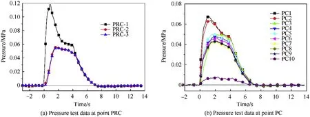
Fig.9.Pressure test results during test-2.
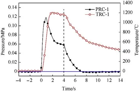
Fig.10.Variation of pressure and temperature in first layer of test-2.
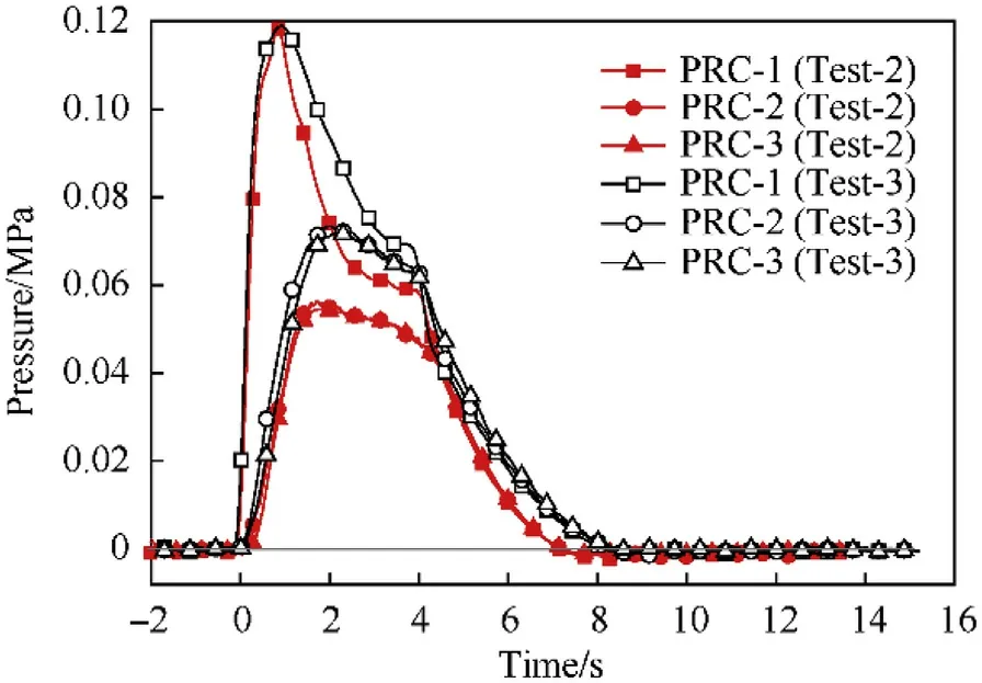
Fig.11.Comparison of ammunition chamber pressure between test-2 and test-3.
As seen in Fig.12,because the motor is placed in the third layer of the ammunition chamber in test-4,the pressure of the third layer is the highest.The pressures of the first and second layers of the ammunition chamber are close to each other and less than that in the third layer.Under test-4 conditions,the negative pressure value measured inside the ammunition store remains relatively weak.The ammunition chamber pressure reached a maximum of 0.07915 MPa at 1.46 s in test-4.Although the pressure relief window of the third layer is smaller in this test,the maximum pressure value is reduced by 32.9% as compared with that of test-2.In addition,the rate of pressure change within the ammunition chamber is significantly smaller.
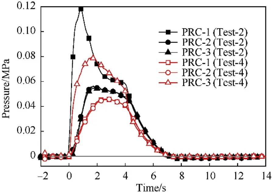
Fig.12.Comparison of ammunition chamber pressure between test-2 and test-4.
The data in Fig.12 show that the pressure of the third layer of the ammunition storage is the largest under test-4 conditions.The closer the measuring point in the relief duct is to the relief window of the third layer of the ammunition chamber,the greater the pressure.In Fig.13,PC6 and PC5 are near the relief window of the third layer of the ammunition chamber,therefore the maximum pressures of points are larger.Meanwhile,for measuring points that are far apart,the maximum pressure is relatively small.In this test,the exhaust cover opening time was approximately 0.09 s.Relative to test-2,the time for opening the exhaust cover in test-4 was 0.03 s earlier.
3.3.Influences of the factors on temperature during pressure relief
Compared with test-1,the maximum temperature of the gas in the ammunition chamber in test-2 is much higher.As listed in Table 3,the internal temperature of the ammunition chamber reaches 1600°C in test-2.Further,there is a large difference in temperature measurements at different points in the ammunition store.The maximum temperature of the measuring point TRC-1 is 1210.3°C,which is 1.96 times that of test-1.Overall,the trend of temperature change is the same as that of test-1.Because of the significant temperature rise inside the ammunition chamber in test-2,the temperature rise on the wall of the ammunition chamber is also large.The peak temperature at the center of the outer wall of the ammunition chamber in test-2 is 130.7°C,which is 2.6 times greater than that in test-1.
The temperature change trend of the data measured in test-3 is basically the same as that in test-2,with the exception of the peak temperatures of TRC-2 and TRC-3,which increased slightly.
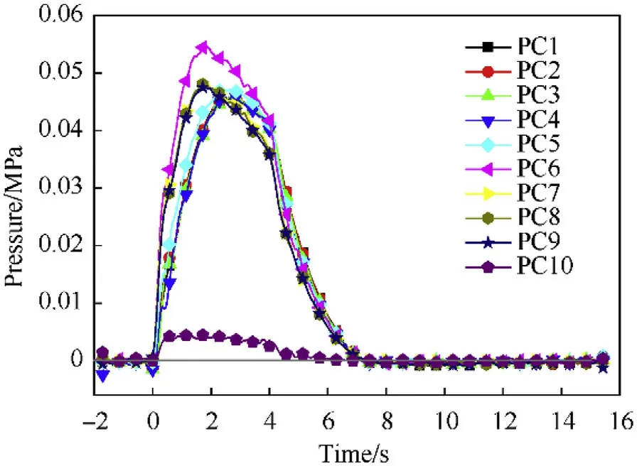
Fig.13.Pressure test results at point PC during the Test-4.

Table 3Maximum measurements of temperature for tests 2,3 and 4.
In test-4,the temperature change law in the first and third layers of the ammunition chamber is different because the position of the accidental ignition of the motor changed from the first layer of the ammunition chamber to the third.Because the volume of the third layer of the ammunition chamber is larger than that of the first,the volume of the original cold air that is used for mixing in the third layer is greater than that in the first layer.The maximum temperature rise of the measured TRC-3 in test-4 was 883°C,which is less than that measured in test-2.
In test-4,when the motor is accidentally ignited in the third layer of the ammunition chamber,high-temperature gas flows into the relief duct through the relief window of the third layer,where it flows to both ends of the duct.Therefore,in the duct,the temperature measurement point closer to the window of the third layer of the ammunition chamber has a higher temperature,and the temperature change occurs earlier.Further,as the positions of measuring points TC5 and TC6 are closer to the window of the third layer of the ammunition chamber,the temperature change occurs at the earliest measured time and increases at the greatest magnitude.Under this test condition,the law of temperature distribution in the relief duct remains the same as the pressure change distribution.
4.Theoretical calculation of pressure relief of ammunition storage
In order to facilitate follow-up research based on this experiment,a theoretical calculation method for missile accidental ignition and pressure relief is proposed to guide the design of ammunition storage.Because the actual model of the ammunition storage is too complicated,the ammunition storage structure was simplified to facilitate the derivation and calculation of the mathematical model.The simplified results are shown in Fig.14.
The red rectangle in the figure indicates the pressure-relief window.The ammunition storage is still in three layers,namely Chambers 1,2,and 3,and the relief window of each layer of the ammunition chamber is A1,A2,and A3,respectively.To better model the actual storage layout,the duct space is divided into two parts,ducts 1 and 2.The two duct spaces are connected through exhaust port A4.The exhaust port A5 on duct 2 is the final exhaust port,simulating the exhaust cover of the ammunition storage.
4.1.Calculation process assumptions
To facilitate the establishment of a mathematical model of the pressure relief exhaust process,the following assumptions were made for the ammunition chamber and gas:
(1)As soon as the exhaust gas from the missile motor leaves the nozzle,it rapidly mixes with the gas in the chamber.The gas in each chamber is in stagnation state.This assumption is acceptable because when the gas leaves the motor,the pressure is equal to the back pressure and the average velocity of gas flow in each chamber is low.
(2)The gas passes through each exhaust port in an isentropic process.Because each port is thickness free,the gas passing through the port is instantaneous,therefore,it is considered to be an adiabatic process.
(3)The maximum velocity of the gas discharged through each exhaust port is the local sound velocity.
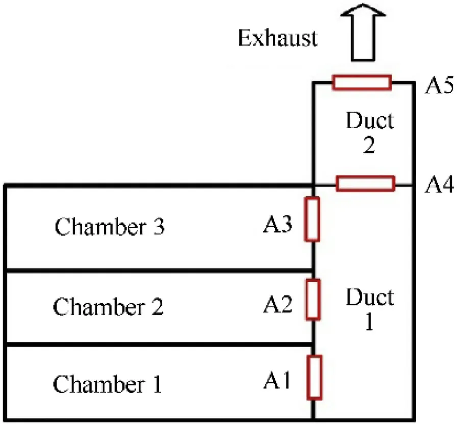
Fig.14.Simplified model of ammunition storage structure.
(4)The physical parameters of the motor gas are the same as those of air.The gas state parameters in each space are uniform.
4.2.State associated governing differential energy and mass flow balance equations
According to the conservation of energy and conservation of mass,the change in mass and total energy of the gas in each ammunition space should be equal to the difference between the mass and energy of the gas flowing in and out of the ammunition chamber through each exhaust port.
Therefore,the total mass of gas in each chamber at timetis as follows:
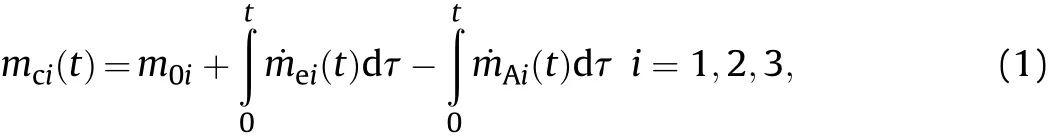
wherem0iis the initial gas mass in each chamber,˙meiis the gas flow rate of the rocket motor accidentally ignited in each chamber,and˙mAiis the gas mass flow rate of each chamber discharged through the port.
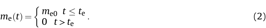
The working time of the missile motor and gas flow rate of the jet areteandme0,respectively.Thus,the gas flow rate emitted by the motor at timetis:
The total energy of the gas in each chamber is:
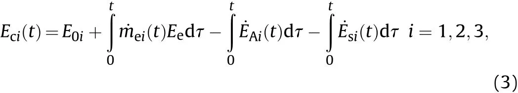
whereE0iis the total energy contained in the initial gas in each chamber,˙EAiis the energy flow contained in the gas discharged from each chamber through the port,Eeis the energy density of the motor,˙Es=λAΔTis the heat dissipation,λis the heat transfer coefficient,andΔTis the temperature difference between the inside and outside.Herein,the value ofλused is 5.62 W/(m2K)[23].
The heat and work exchanged between the airflow and the outside is equal to the change of the total enthalpy of the airflow[29].Therefore,the total enthalpy is used to represent the total energy of the gas flow.So,the temperature in each ammunition chamber is given by:

The gas density is:

whereVciis the volume of each ammunition chamber.
According to the ideal gas state equation,P=ρRT,Eq.(4),Eq.(5)can be introduced into the above equation to obtain the pressure at timet:
For the space of the exhaust duct,the rocket motor related part is removed from the calculation.The remaining calculation methods are consistent.
4.3.Developed equations for exhaust area locations
The gas in each layer of the ammunition chamber flows because there is a pressure difference.At each exhaust port of the ammunition chamber,the direction and velocity of the airflow are determined according to the pressure difference existing inside and outside the exhaust ports.Therefore,the gas mass flow is limited by the area of the exhaust ports.
Using relief window A1 as an example,at time t,the pressure inside and outside the port is compared.
1)WhenPc1(t)≥Pd1(t)(wherePc1is the pressure in chamber 1 andPd1is the pressure in duct 1),the gas flows from chamber 1 to duct 1.
According to the one-dimensional isentropic flow formula of the gas,the Mach number of the gas passing through A1 can be obtained using the equation:
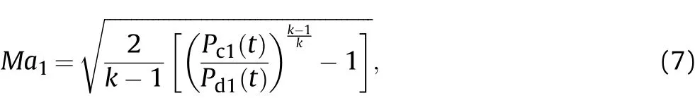
wherekis the gas adiabatic index.Note that the default is equivalent to air,which is 1.4.
WhenMa1≥1,we useMa1=1.
According to one-dimensional isentropic flow,there are:

whereTc1is the temperature of the gas in the ammunition chamber 1,andT1is the temperature of the air flow through the exhaust port before mixing.
The local sound velocity on the downstream side of the exhaust port is:
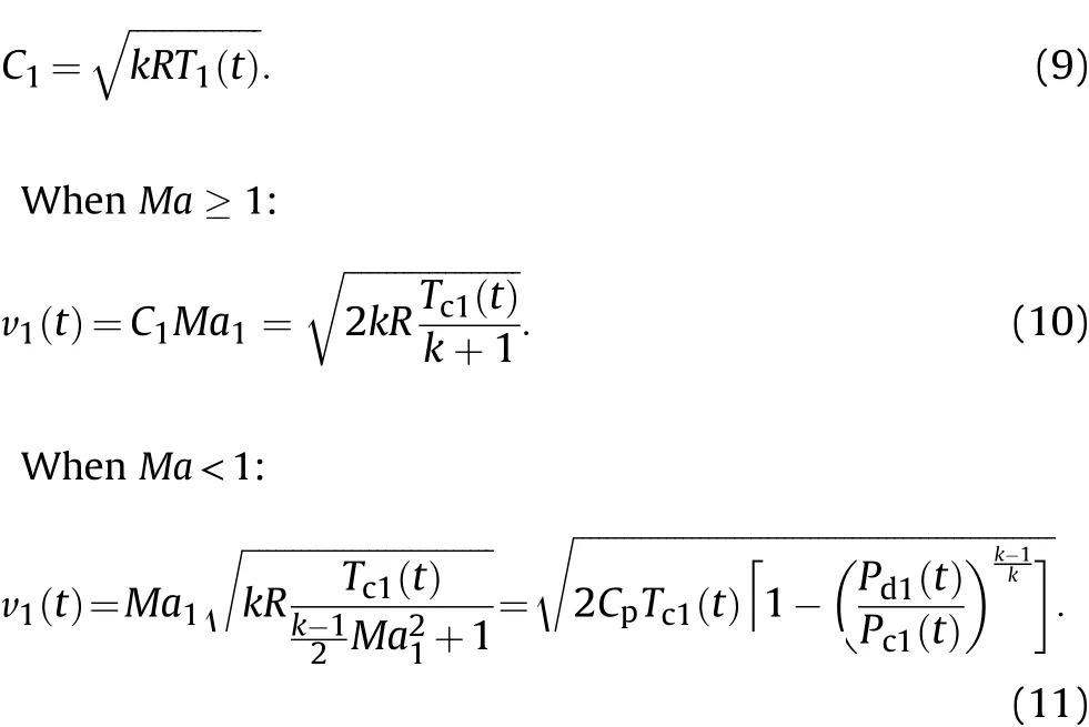
As a result of isentropy,the relationship between the parameters of gas flow before and after window A1 can be obtained as follows:
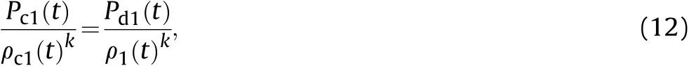
whereρ1is the density of the gas on the downstream side of the exhaust port.
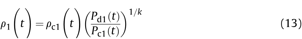
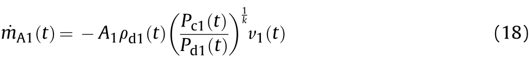
The mass flow rate of the gas flowing through the relief window A1 at timetis determined using Eq.(14):
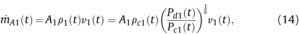
whereA1is the area of the opening A1.
The energy flow rate of the gas flowing out through A1 at time t is:2)WhenPr1(t)<Pc1(t),gas flows from duct 1 to chamber 1.
Thus,the calculation for the gas Mach number passing through A1 is:
According to Eq.(16),we obtain the gas velocity discharged from the relief window A1 under different Mach numbers.

The mass flow rate of gas flowing out of the ammunition chamber 1 through A1 at timetis:
Fig.15.Comparison of experimental data and theoretical calculation data.
The energy flow rate of the gas flowing out of the ammunition chamber 1 through A1 at time t is
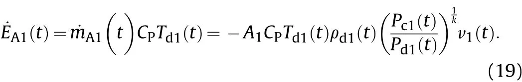
Similarly,the mass flow and energy flow of the gas passing through the port are obtained at timetfor other ports in the ammunition storage.
However,unlike the other ports,which are always open,exhaust port A5 transitions from closed to open.Before the exhaust cover is opened in the initial stage,whenPd2(t)<Pj+Pb(wherePjis the warning overpressure value of the exhaust cover open,andPbis the ambient pressure),A5=0,then:
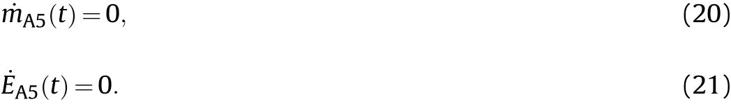
After the exhaust cover is opened,the flow calculation method is the same at the other exhaust ports.
4.4.Solution method and result
The Euler method was used to calculate the gas mass and total energy in each chamber as follows:
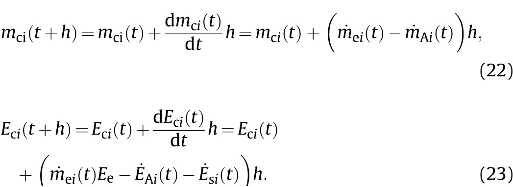
Using Eqs.(4)-(6),the temperature,density,pressure,total mass,and total energy of the gas in each chamber and duct can be calculated.
The pressure calculation results of each chamber in test-1 were compared with the experiment results of test-1 in Fig.15.It can be seen that the theoretical calculation method proposed in this study is in good agreement with the experimental results.
5.Underground ammunition storage safety protection
The existing safety regulations related to various types of ammunition storage have no guidelines regarding how to design the discharge capacity of gas flow or how to reasonably design the size of an exhaust port.In view of the experimental and theoretical results of this work,the following suggestions are proposed for the protection of ammunition storage:
1)The multi-chamber structure of the underground ammunition storage can help to disperse related dangers.Limit the spread of high temperature gas.The temperature rise and pressure rise of the environment caused by the ignition of solid rocket motor is constrained in one space to reduce the damage to the rest of the space.
2)The pressure relief structure in underground ammunition storage should consider both the area of the final exhaust outlet,even if it has the smallest area,and the cross-sectional area of the pressure relief duct.The design of the pressure relief ducts should be as short and as straight as possible.
3)More dangerous ammunition should be placed in the chamber with the shortest relief duct to reduce the potential degree of damage.
6.Conclusions
In this study,the change laws of temperature and pressure in underground ammunition storage before and after opening a pressure relief device was studied experimentally to simulate the accidental ignition of a solid rocket motor.The pressure and temperature distributions and variation law of high quality and high temperature gas injection in the confined space with multiple layers and pressure relief ducts were obtained.The effects of gas flow rate,the ignition position of the solid rocket motor,and final exhaust pressure relief area of ammunition storage on the pressure and temperature distribution were also studied.In addition,based on the experimental results,a theoretical method for calculating pressure variation with time during the decompression process of ammunition storage was proposed for the scenario in which a missile is accidentally ignited.Finally,some suggestions regarding safely designing ammunition storage were proposed.
The detailed experimental findings are as follows:
●In the case of an accidental missile ignition in underground ammunition storage,the interior pressure and temperature of the chamber rise sharply.The pressure distribution in the chamber is relatively uniform,while the uniformity of the temperature distribution is poor.In our tests,the peak temperatures appear at the end of motor operation,which is later than the peak pressure.The pressure drop process is influenced by the gas flow rate and chamber structure.●The multi-space layout of underground ammunition storage
makes the obstacle of temperature propagation far greater
than the pressure when the missile is accidentally ignited.●When the motor gas flow rate increases to 5.6 times the original rate,the maximum pressure of the ammunition storage increases 5.87 times,and the opening time of the exhaust cover is advanced by 70%.The maximum value of temperature measurement at the same measuring point of ammunition storage doubled,and the temperature measurements on the outer wall increased by 1.6 times.●Under a certain motor flow rate,the area of pressure relief exhaust at the end of the relief duct decreases by 1/2,which causes the pressure of the ammunition storage in the second and third layers to rise by 30.4%and 32.1%,respectively.The peak temperatures of these layers also increases.However,the maximum pressure of ammunition storage in the first layer does not increase significantly,lowering the rate of pressure relief,thus delaying the time for the pressure of the ammunition storage to drop to zero by 0.9 s.
●The maximum pressure can be reduced by 32.9% when the ignition position of the motor is set in the third layer of the ammunition chamber and reduces the rate of pressure change.
●After motor operations finish,the heat dissipation effect of the ammunition storage structure leads to a negative pressure state.Thus,the gas returns to the ammunition storage at the exhaust port.The strength of reflux and negative pressure phenomena is related to the motor flow rate,heat dissipation conditions,and other factors.
●The theoretical calculation method for the pressure release of the ammunition storage has been provided.It can be used to guide the pressure relief design of ammunition storage in case of accidental missile ignition and improve the safety of ammunition storage.
Declaration of competing interest
The authors declare that they have no known competing financial interests or personal relationships that could have appeared to influence the work reported in this paper.
Acknowledgements
The work described in this paper was supported by the Natural Science Foundation of China(Grant number:NSFC11572095).

- Defence Technology的其它文章
- Defence Technology
- Mitigation effects on the reflected overpressure of blast shock with water surrounding an explosive in a confined space
- Fabrication and analysis of TIG welding-brazing butt joints of in-situ TiB2/7050 composite and TA2
- Effect of the end cap on the fragment velocity distribution of a cylindrical cased charge
- A novel DOA estimation algorithm using directional antennas in cylindrical conformal arrays
- Research on the intermediate phase of 40CrMnSiB steel shell under different heat treatments