Research on the intermediate phase of 40CrMnSiB steel shell under different heat treatments
Wei-bing Li,Zhi-chuang Chen,Xiao-ming Wang,Wen-bin Li
ZNDY of Ministerial Key Laboratory,Nanjing University of Science and Technology,Nanjing,210094,China
Keywords:Explosive mechanics Mid-explosion recovery experiment Explosion and fracture Heat treatment SEM(Scanning electron microscope)fracture analysis
ABSTRACT
1.Introduction
The dynamic process of expansion and fracture of metal cylindrical shells under high-strain-rate loading has long been a focus of study[1,2].It has been found that the crack initiation and propagation of the metal casings under an explosive loading,are closely related to the mass distribution,the scattering velocity and angle of the fragments[3,4].As early as the 1940s,Mott et al.[5]proposed a theoretical calculation model for the fragment circumferential size based on stress wave theory and probability statistics.Later,Grady et al.[6]further considered that fracturing is not instantaneously completed and thus introduced the cohesive zone model,ultimately establishing a dynamic crushing theory based on energy.Stronge et al.[7]have studied the expansion and fracture characteristics of ST-series and HF-1 steel cylindrical shells after different heat treatment conditions.And the variation law of the fracture strain with the strain rate was obtained.Moreover,the validity of the two types of fracture criterion based on strain(strain rate independent)and energy(strain rate dependent)was compared and analyzed.To more thoroughly understand the mechanism of metal expansion and fracture,some studies have been conducted at the microscopic level.These studies have found that the dynamic response of the metal shell under a high strain rate is closely related to the microstructure of the shell material.For example,Beetle et al.[8],Sun et al.[9],Ren et al.[10]and Sunwoo et al.[11]have observed the fracture morphology characteristics of the casings via SEM and have deduced the metal shell fracture process and/or the material phase transition process.Jin et al.[12]have used high-speed photography and metallographic analysis to research the effect of different tempering conditions on the expansion and fracture characteristics of 45 steel casings under blast loading.Zhu et al.[13]have investigated the fracture mechanism of the 40CrMnSiB steel tempered with different temperatures through high-speed photography experiment and SEM analysis of the recovered fragments.It was found that steel tempered at higher temperatures delayed the generation of the cracks on the casing surface,the occurrence of fracturing and the leakage of the detonation product.However,the high-speed photographic images obtained could not clearly observe the specific distribution of the surface cracks.The microscopic fracture mechanism of the fragment also could not distinguish the difference in the axial direction.Therefore,further study is necessary for the high-strain-rate expansion deformation,crack initiation and fracture mechanism of the warhead.
Currently,experimental studies of the expansion and fracture process of metal cylindrical shells under a high-strain-rate loading are mostly carried out by optical photography[14,15].Additionally,analyzing the recovered fragments is also a commonly used research method[16,17].Optical photographic technology cannot observe the internal crack initiation position,pattern,and propagation in the shell.Meanwhile,constrained by the optical vision boundaries and the image quality of photographic equipment,the resulting images cannot completely and accurately observe the propagation of the cracks in the entire cylindrical casing.Moreover,under the internal explosive loading,the metal shell will form many small fragments.Thus,it is not possible to completely patch these fragments together into the original shape of the cylindrical shell.And it is also impossible to obtain the axial and circumferential fracture parameters of the shell.According to Reference[18],as early as the 1950s,scholars in the former Soviet Union proposed the idea of applying a massive recovery device to terminate the expansion of the shell at a certain position.In this way,the shell wreckage exhibiting a relatively complete shape can be used to investigate the crack distribution characteristics and the fracture mechanism of the cylindrical shell under a high-strain-rate loading.However,few published test results have been reported in the published literature[19],and the relationship between the tempering temperature and the final fragment formation size needs further study.In order to better to describe the process of initiation cracking phase to the final fragmentation phase under high-strain-rate loading,it is necessary to study the fracture morphology of the metal casings at an intermediate phase.
In this work,for the 40CrMnSiB steel at different tempering temperatures,a mid-explosion recovery experiment had been designed to recover the mid-state cylindrical shell with crack information.Then,the influence that the tempering temperature has on the fracture characteristics and the distribution of the crack propagation was studied.The variation law of important fracture parameters at different tempering temperatures such as the circumferential divide size was revealed.In addition,the influence of the axial position and tempering temperature on the microscopic fracture characteristics of the shell was discussed using SEM analysis.
2.Experiment on mid-explosion recovery of metal cylindrical under internal explosive loading
2.1.Experimental design
A standard cylinder with a 50 mm inner diameter,an 80 mm length,and a 6 mm thickness was used as the structure of the casings.The CL-20-based pressed composite explosive with a length of 80 mm was employed for detonation,and the detonation point was located at one side of the center of the cylinder.In addition,two end covers constructed of 45# steel were connected to the shell by a screw threading.The specific structure of the warhead is shown in Fig.1.40CrMnSiB alloy steel was used as the casing material,which was tempered at 350 500 or 600°C after quenching at 860°C.Six experimental devices are prepared in the test,two for each tempering temperature.The performance parameters of the shell material under these three different tempering conditions are shown in Table 1.The characteristic parameters of the CL-20-based high-energy explosive are listed in Table 2.
2.2.Experiment layout
The experimental layout of the device used for the midexplosion recovery of the intermediate phase of expansion and fracture of the metal cylindrical casing is shown in Fig.2.To effectively compare and analyze the differences between the shell wreckages under the same constraints,the new and same recovery devices made of 60Mn2Si high-strength alloy steel were applied in each experiment.It is important in the design of the recovery device to determine the proper inner diameter of the device.Therefore,the initial inner diameter of the recovery device was confirmed with reference to the theory of Taylor[20].Therein,it is considered that the fracture radius(af)of the cylindrical shell under an explosive loading can be calculated as

wherea0is the initial outer radius of the cylindrical casing(a0=31 mm);kis the adiabatic constant(k=3);PHis the denotation pressure of the Chapman-Jouguet detonation wave(PH=38.3×10³MPa);andσsis the yield strength of the metal casing(σs=1080 MPa,where 40CrMnSiB steel tempered at 500°C was selected as the reference).According to the theory,the outer diameter of the casing at fracture is 97.75 mm.So,the initial inner diameter of the recovery device was chosen to be 100 mm.The warhead was placed at a fixed position in the center of the recovery device.The warhead and device together were placed in an explosion crater with a diameter of 400 mm and a depth of 500 mm.A polyfoam board was placed below the device as a buffer layer to unload the detonation product in the axial direction,and to subsequently reduce the shock effect of the detonation product on the bottom of the device.
3.The effect of tempering temperature on fracture characteristics of 40CrMnSiB steel cylinder shell
3.1.Experiment results
Using the experimental scheme shown in Fig.2,the wreckage of the 40CrMnSiB steel cylindrical shells at the intermediate phase of the expansion and fracture was acquired,and are shown in Fig.3.In the experiment,it was observed that the inner diameter of the recovery device was slightly enlarged under the strong impact of the metal casing.Further,a number of cracks were observed on the inner wall surface of the device but no serious rupture occurred,as shown in Fig.4.These phenomena indicate that the casings did not expand outward substantially after impacting the inner wall of the recovery device.Therefore,the constraint on each of the casings recovered in this way can be considered to be identical.Disregarding the end covers,the recovery rate of the cylindrical shell is greater than 90%,basically achieving complete recovery.Analysis of the recovered wreckage shows that,under the same constraint condition,the degree of crushing of the shell tempered at 350°C is greater than the others.In contrast,the cylindrical shells tempered at 500 and 600°C,which possess high fracture toughness and higher dynamic plasticity,exhibited delayed cracking that resisted crack extension.Thus,the casings recovered by the device are still exhibiting the sliding phase at the moment of recovery.In terms of the overall structural integrity of the recovered shell wreckage,under the same internal explosive loading,the structural integrity of the shell tempered at 500°C is the best,and 350°C is the worst.This means that the complete fracture time of the shell tempered at 500°C was delayed and the corresponding fracture radius was larger.The detonation product can drive the shell tempered at 500°C more adequately before leaking from the cracks.Therefore,compared to the other two shells,the shell after tempering at 500°C has higher kinetic energy originated from detonation products.This conclusion is consistent with that gained in the previous ultra-high-speed photography experiments[9].
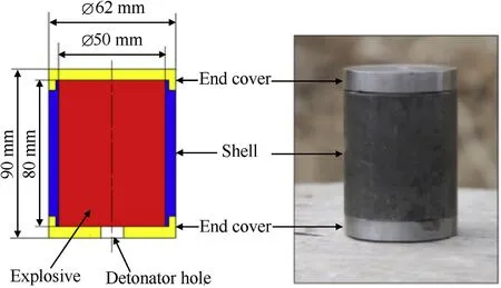
Fig.1.Schematic(left)and photograph(right)of the warhead structure.

Table 1Main parameters of the shell material used for simulation models[5].

Table 2Parameters of high-power explosive CL-20.
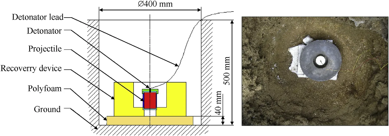
Fig.2.Schematic illustration of the experiment(left)and top-view photograph of the actual experiment in the explosion crater prior to detonation(right).
3.2.Fracture pattern analysis

Fig.3.Photographs of the wreckage recovered from the metal shells treated at tempering temperatures of(a)350,(b)500 and(c)600°C.
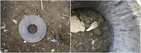
Fig.4.Photograph of the recovery device after the strong impact of the metal shell showing a wide-angle top view(left)and a close-up top view of the inner wall(right).
Tempering heat treatment changes the internal microstructure of the material,such as grain size,crystal defects,alloy element solubility,etc.,and initiates the solid phase transition of the material.These subtle changes in the microscopic scale will cause corresponding variations in the macroscopic mechanical properties of the material.Since the fracture separation of materials is a complex cross-scale problem,the variations in the microscopic scale will also have an important impact on the fracture characteristics of the material.Here,it is mainly reflected in the changes of the fracture behavior,fracture pattern and fracture size of the shells caused by the tempering temperatures.The macroscopic fracture characteristics of the shells developed with different tempering temperatures are analyzed,as shown in Figs.5-7.The macroscopic analysis of the wreckage of the shell tempered at 350°C is shown in Fig.5.Two kinds of fracture patterns were observed in the fragments:shear fracture and tensile-shear fracture.In addition,the fracture pattern was not consistent along the axial direction.Fig.5(a)shows that,from the detonation initiation end to the noninitiation end,the radial fracture patterns sequentially exhibited as a dual-directional shear fracture and tensile-shear fracture.The recovery results of the shells tempered at 500 and 600°C are shown in Figs.6 and 7,respectively.The fracture pattern of these shell is essentially a through-type shear fracture.However,owing to the strong restraint of the recovery device,the fracture surfaces have a certain degree of curvature.
Moreover,the three different shells exhibited a similar phenomenon.It is that many cracks do not penetrate the entire wall thickness and the number of cracks on the inner wall exceed that of the outer wall.Under the explosive loading,the shear crack initiations at the inner wall of the shell and then extend along the shear band to the outer wall.At the same time,the shell on both sides of the crack near the inner wall enter the slide-separated state firstly to form fracture surface 1.According to the unloading wave theory of Mott,at the time of fracture,the unloading wave is released from the fracture and propagated into the shell on both sides of the fracture.The area propagated by the unloading wave is unloaded to the rigid state and the growth of the crack in this area is inhibited.Due to the mutual unloading effect between the cracks,a few cracks with earlier initiation time and higher propagation velocity dominate in the mutual shielding competition.These cracks extend to the outer wall to form sliding fracture surface 2.Finally,resulting in the number of cracks at the inner wall exceeded that at the outer wall,as shown in Fig.8.

Fig.5.Photographic analysis of the recovered casing tempered at 350°C,showing(a)tensile-shear and dual-directional shear fracture,(b)unidirectional shear fracture and(c)the cracks in the inner surface.

Fig.6.Photographic analysis of the recovered casing tempered at 500°C,showing the casing in the(a)lateral direction,(b)the interior view and(c)step plate.
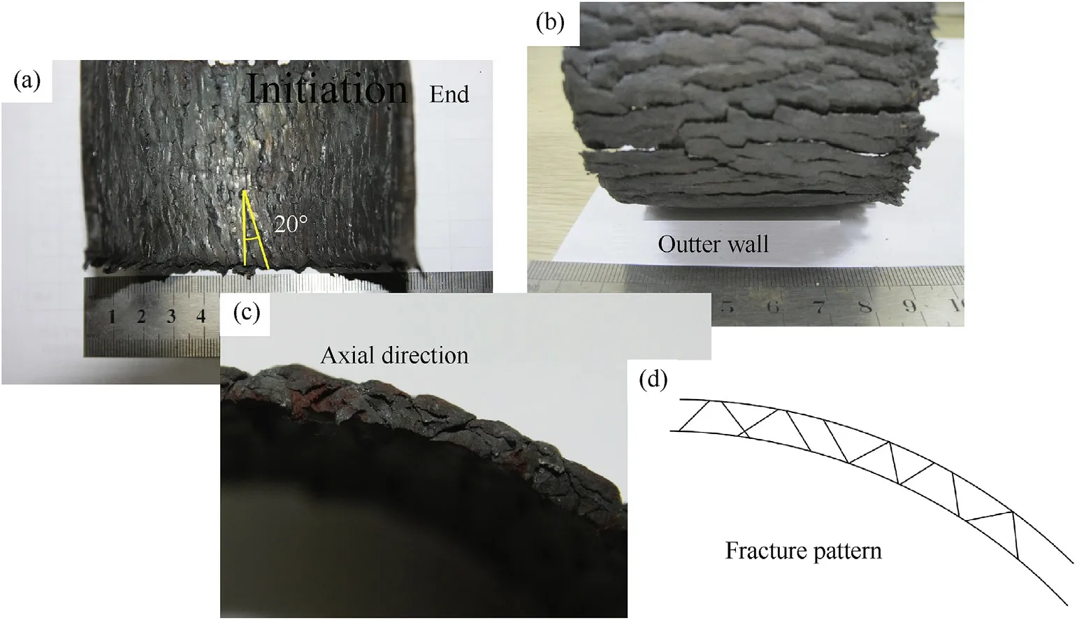
Fig.7.Photographic analysis of the recovered casing tempered at 600°C,showing the casing(a)interior view,(b)outer wall view and(c)a shear fracture.
3.3.Fracture path analysis
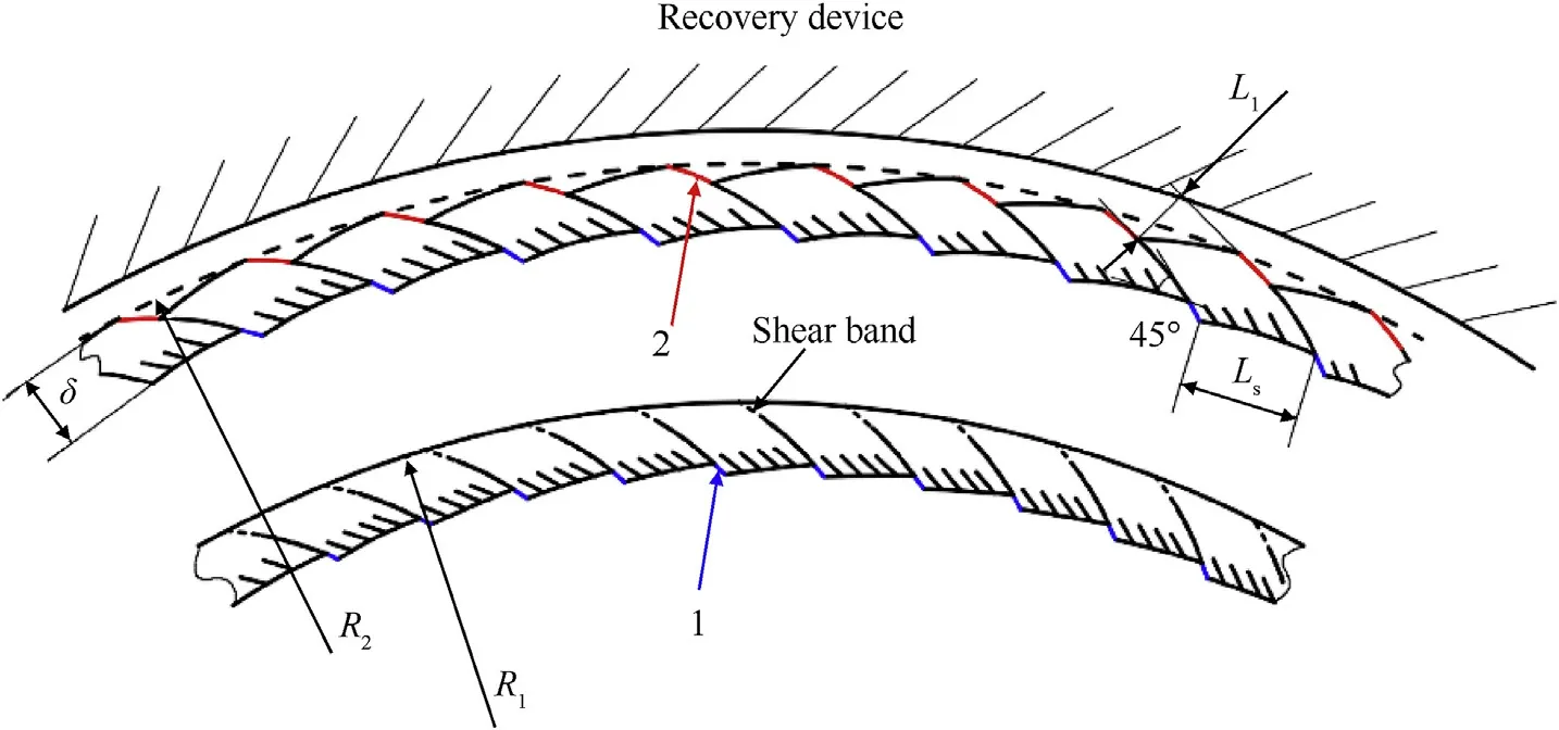
Fig.8.The fracture pattern of the expanding metal shell.
Fragments are the final products of crack initiation,growth,and mutual convergence in three-dimensional space.There-fore,the fracture path of the cracks directly determines the shape and size of the final fragments.
Many axial cracks can be found in the recovered shell wreckage which almost extends throughout the length of the shell.The propagation path of the crack in the axial direction can change several times,forming step plates at local positions,as shown in Fig.6(c).These long axial cracks do not extend from a single fracture source to the entire length of the shell but are instead formed by the convergence of the shear fracture cells that originated at different axial positions[21].Under the high strain rate loading,the fracture pattern of the shell in the radial direction is dominated by adiabatic shear fracture.Since the early fracture initiation in the upstream section has a great influence on the location of the fracture and the fracture pattern in the downstream section.Many long cracks that parallel axial direction are formed in the shell.However,the specific location of the shear fracture cell is also impacted by the microscopic defects of the material.So,the longitudinal propagation paths of these cracks constituted of the cells are not strictly parallel to the central axis of the shell.The faces of the fracture cells are not on the same plane,but each face roughly parallel to the axis,and there is a small circumferential spacing between the adjacent faces,as shown in Fig.9.After the shear fracture actuated,the medium surrounding the cells is unloaded and restored to a rigid state when these shear fracture cells propagated in the axial direction.The crack propagation energy is provided by the plastic deformation energy in the medium.The material in the rigid state cannot continue to provide energy for the crack propagation.Leading to the adjacent fracture cells cannot intrude into each other’s unloading area in the original propagation direction at the t3moment.However,owing to the weak region between the two crack tips,at the t4 moment,the stress field at the crack tip changes under the sustained action of the shells on both sides of the crack,resulting in circumferential tear behavior.The tearing along the circumferential direction finally achieves the mutual convergence of the fractured cells and forms a nearly vertical step-like fracture feature.
3.4.Analysis of the influence of tempering temperature on fracture parameters
The fracture parameters of the shell wreckage including the following aspects:the linear distance between adjacent shear fracture surfaces,Lt(i.e.,the circumferential divide size of the shell);the thickness of the recovered wreckage(δ);the number of circumferential divisions(Nc),which are illustrated in Fig.8.These parameters can be used to evaluate the performance of the warhead to form fragments in the circumferential direction.However,before measuring and analyzing these fracture parameters,it is necessary to investigate the effect that hard-recovery experiment may have on these parameters.According to the fracture morphology of the recovered shell wreckage,fracture surface 2 had slipped out of the shell outer wall to a large extent.Although the recovery device inevitably had a strong impact on the shell during the freezing process,the wall surface and the fracture surface on the outside of the shell can still be easily distinguished.The number of circumferential divisions can be determined,subsequently.Considering the changes of the shape and size of the outer wall surface of the shell caused by the strong impact.The linear distanceLsbetween two adjacent shear cracks on the inner wall surface was directly measured.Then,the circumferential divide sizeLtwas gained by the following equation:

In order to study the changes of shell fracture parameters caused by different tempering temperatures,the region near the central position on the inner wall of the shell was selected as the statistical location(i.e.,the area between B and C in Fig.6(b)).Fifty cracks were selected in each shell,and the linear distances between the adjacent cracks on two different cross-sections were directly measured and recorded.Then the linear distance between adjacent shear fracture surfaces(Lt)was gained by the Eq.(2).Therefore,a total of 100 statistical samples were acquired in each of the shells,which are shown in Fig.10.Additionally,the average thickness(δave)and the number of circumferential divisions(Nc)of the recovered wreckage was also measured and calculated.These data are listed in Table 3 together with the average circumferential divide size(Lave).
Combined with the data given in Fig.10 and Table 3,in the initial stage,the increasing tempering temperature(from 350°C to 500°C)significantly improves the dynamic plasticity and fracture toughness of the 40CrMnSiB steel.Thus,the shell easily enters a yield state under internal explosive loading.The expansion radius of the shell and the corresponding fracture characteristic parameter changes distinctly.Laveincreases from 3.18 mm to 3.56 mm(increased by 11.9%);δavedecreases from 3.79 mm to 3.44 mm(reduced by 9.2%),and the corresponding fracture strain(εf)increases from 0.37 to 0.43(whereinis the initial thickness of the casing);Ncdecreases from 84 to 73(decreased by 16.1%).However,when the tempering temperature further increased from 500°C to 600°C,the effect of the decrease in the dynamic strength of the material caused by the heat treatment will become obvious.And partially cancel out the influence caused by the improvement of the dynamic plasticity and fracture toughness.Finally,leading to an unobvious change of the fracture characteristic parameters.Laveincreases from 3.56 mm to 3.64 mm(increased by 2.2%);δaveincreases from 3.44 mm to 3.54 mm(increased by 2.9%),and the corresponding fracture strain(εf)decreases from 0.43 to 0.41;Ncincreased from 73 to 75.
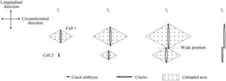
Fig.9.The representation of the growth and convergence of the adjacent shear fracture cells.

Fig.10.Distribution of the circumferential divide size of the shells with different tempering temperatures.

Table 3The fracture characteristic parameters of the shell wreckage.
In order to theoretically predict the average circumferential size of the recovered fragments under high strain rate loading,based on the Mott unloading wave theory,Grady[14]further considers that the fracture is not instantaneously completed.The material fracture energy(Gc)that based on the cohesive force model is introduced to a one-dimensional ideal rigid-plastic rod.The characteristic time of the fracture is deduced,twice the Mott unloading wave propagation distance within this time is the average circumferential size of the fragments.The formula for predicting the average circumferential size of fragments at a high strain rate proposed by Grady is given as

whereLGradyis the average circumferential size of the fragments;ρ is the material density;˙εis the average circumferential tensile strain rate at the fracture time;Gcis the fracture energy,for the shear fracture,it is given as[22].

wherecis specific heat capacity;αis thermal softening coefficient;χis the thermal diffusion coefficient,χ=k/(ρc),kis the thermal conductivity;Yis the flow stress;˙γis the shear strain rate,which can use the circumferential tensile strain rate(˙ε)as an approximation[23].According to reference[24],at the fracture time,the circumferential tensile strain rate of the shells tempered at 350°C,500°C and 600°C is 4.94×10⁴s-1,5.3×104s-1,5.25×104s-1,respectively.The relevant fracture energy parameters of 40CrMnSiB steel for different tempering states are shown in Table 4.The experimental and theoretical values of the average circumferential divide size are plotted in Fig.11.
From the data in Fig.11,when the tempering temperature increases,the predicted value of the average circumferential divide size based on the Grady model is gradually reduced,while the experimental value is gradually increased.In addition,for the casing tempered at 350°C,the difference between the theoretical values and experimental values is the largest,reaching 25.0%.As the tempering temperature increases from 350°C to 500°C,the fracture energy of the material decreases continuously.The theoretical solution of the circumferential size of the fragments based on the fracture energy also decreases accordingly.Owing to the complexity of the material fracture problem,the circumferential size of the fragments cannot be described simply by the fracture energy.It is also necessary to give a certain explanation from the microscale for the actual fracture problem.
After quenching at 860°C,the microstructure of 40CrMnSiB steel consisted of quenched-martensite and a small amount of retained austenite.The martensitic phase transition temperature of 40CrMnSiB steel isMs=362°C.Therefore,at the tempering temperature of 350°C,only austenite transformed,the content of martensite almost unchanged,and the final microstructure is tempered-martensite.Martensite has high strength but poor toughness,making the material more prone to brittle fracture under high strain rate loading.This fracture property is somewhat different from the cohesive fracture model,resulting in a larger difference in the result.When the tempering temperature increased to 500°C and 600°C,the martensite gradually decomposed and finally formed tempered troostite composed of ferrite matrix and fine-grained cementite.Although the strength of ferrite matrix is low,its toughness is good,and plastic deformation is easy to occur.Under high strain rate loading,the ductile fracture is more likely to happen,which is consistent with the cohesive force fracture model used by Grady calculation model well.
4.Observation and analysis of microstructure of recovered shell wreckage
4.1.Microscopic fracture mechanism of fractures at different axial positions
To study the microscopic fracture mechanisms at different axial positions,the shell wreckage tempered at 350°C was selected as the research object.The fracture surfaces at the detonation initiation end(Fig.12)and that near the middle(Fig.13)were observed carefully by a FEI Quanta 250FEG SEM equipped with an EDS system.Fig.12 shows that the fracture surfaces near the initiation end have distinctly different fracture characteristics at different locations.The area near the outer wall(area A in Fig.12(a)and(b))andthe area near the inner wall(area B in Figs.10(a),Fig.12(c))were magnified and characterized.The fracture surface in Fig.12(c)does not exhibit the typical dimples caused by shear fracturing,but instead presents a flow-like structural feature with obvious directionality.Under the great pressure impact of the detonation products,the shear cracks near the inner wall are guided by adiabatic shear bands during fracture.Accompanied by the formation of these adiabatic shear bands,severe plastic deformation occurs in the in-band organization and generates the temperature effect.The material in the band is softened but still maintaining a“weak continuous”state.Subsequently,the relative movement of the shells on both sides of the shear band eventually leads to the generation of cracks that then extend along the shear band.Therefore,the direction of the flow structure is related to the relative movement direction of the casing in the relative sliding state.Further observation reveals that the direction of the flow-like structure is not always in the radial direction of the cylindrical casing.Signifying that,in the relative sliding state,the relative movement of the casing near the detonation position is not only along the radial direction.In particular,the closer the casing is to the inner wall,the greater the axial motion component of the relative motion.Fig.12(b)shows a number of scratches whose extension direction are parallel to the radial direction of the casing.These occur because the fracturing in the vicinity of area A in Fig.12(a)is formed after the shell collides with the recovery device.During the collision process,the strong interaction between the shell material on both sides of the fracture caused the fracture surface to be severely squeezed and scraped,ultimately forming scratches.

Table 4Relevant parameters of shear fracture energy.
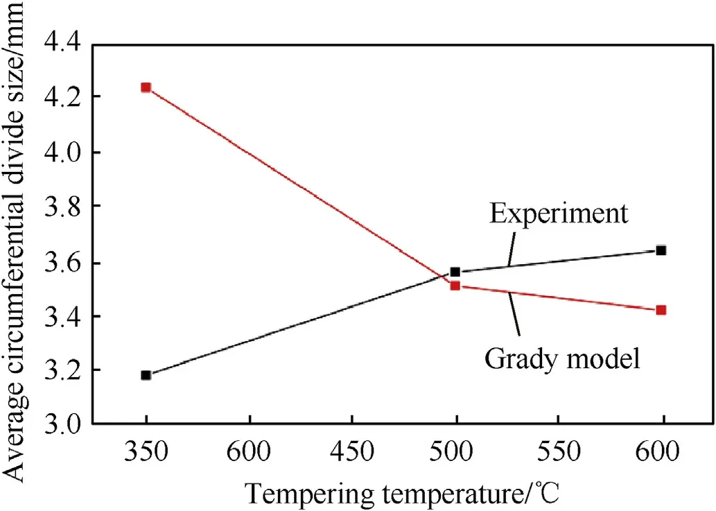
Fig.11.The comparison of the average circumferential divide size between experiment and Grady model.

Fig.12.SEM images of the fracture near the initiation end showing(a)a wide-angle view and(b,c)a higher-definition view of the areas marked in(a)as(b)area A and(c)area B.

Fig.13.SEM images of the fracture near the middle of the casing showing a wide-angle view(left),and a higher-definition view of the area marked C(middle)and marked D(right).
Fig.13 shows the fracture surface observed near the middle of the shell.Two types of steps in the radial and longitudinal directions could be observed in Fig.13(a).To study the formation mechanism of these two steps,the fracture surface of two areas(marked C and D in Fig.13(a))was further magnified for characterization in Fig.13(b)and(c),respectively.The fracture morphology in Fig.13(b)appears as mostly an uncharacteristic flat surface,also known as a flat or extended area,which is a typical feature of a sliding separation fracture.Fig.13(c),however,exhibits flow-like structural features whose direction is approximately parallel to the radial direction(i.e.,going from the inner wall to the outer wall),whereby it is inferred that the fracture initiation point is near the inner wall.Contrasting Fig.13(b)and(c),the microscopic fracture characteristics of the upper and lower sides(i.e.,areas C and D in Fig.13(a))of the radial step differ significantly.This reflects the microscale nature of the axial cracks being made up of many tiny crack cells that are relatively independent.Expansion of a crack always follows the principle of least energy consumption,and the formation of the steps requires the consumption of additional energy.So the height of these radial steps gradually decreased along the radial direction until disappeared,and eventually formed larger longitudinal crack cells.To investigate the formation mechanism of a longitudinal step,the flow-like structural features of the left and right sides of the longitudinal step in Fig.13(c)were studied.No difference is apparent between the two flow-like structures in this direction from the inner wall to the outer wall.Therefore,the possibility can be eliminated that two cracks extending from opposite directions converge to form the step.The longitudinal steps were instead caused by a change of the crack propagation path,which originated near the inner wall.The propagation path of the crack always follows the shear band,and the specific choice also follows the principle of least energy consumption.
The fracture morphologies of the two axial positions of the initiation end(Fig.12)and the middle position(Fig.13)were compared and analyzed.The fracture surface at the initiation end of the shell has a distinct tearing feature,and the flow-like structure near the inner wall is approximately along the longitudinal direction.Nevertheless,the direction of the flow-like structure near the middle of the shell exhibits a substantial radial direction.From these microscopic fracture characteristics,affected by the axial sparse wave,the fracture behavior of the shell at the initiation position is different from that of the middle position.Near the middle position of the casing,the shear crack cells form at the area near the inner wall and extend radially.Meanwhile,these crack cells gradually converge in the axial direction and ultimately run through the entire wall thickness.In contrast,the fracture at the detonation initiation end is formed by tearing along the crack,which occurs a distance from the initiation position and propagates along the axis direction.
4.2.Comparison of SEM images of the shell wreckage tempered at different temperatures
Fig.14 shows higher-resolution SEM images of the wreckage of shells tempered under three different temperatures.The flowstructure characteristics are more obvious in the fracture surface of the shell tempered at 350°C.The temperature of the internal organization of the adiabatic shear band is related to the flow stress of the material.In this relation,a greater flow stress in the material induces more plastic deformation work performed by the local deformation of the band and a higher amount of generated heat[18].After 350°C tempering,the strength of the material is higher than that of the other two materials,and therefore more heat is generated during the formation of the shear bands.Correspondingly,more serious melting occurs in the microstructure at the fracture surface,resulting in more prominent flow characteristics.In addition,there are a large number of spherical particles coated with bright contrast matter(i.e.,white color in Fig.14)on the fracture surface.Energy dispersive X-ray spectral analysis concludes that these spherical particles are likely alloy carbides precipitated from the carbon-rich quench-induced martensite created in the tempering process,wherein the specific composition is shown in Table 5.Owing to the natural oxidation of the sample placed in the air for a long time,the oxygen element content of the alloying carbides is abnormally high.The precipitation of alloy carbides is positively correlated with the tempering temperature,so the number of carbide particles in the shell after tempering at 600°C is the largest,as shown in Fig.14(c).Alloying carbides precipitated during the tempering process can improve the strength of the steel by means of dispersion strengthening.However,it cannot completely offset the reduction in the strength caused by the decomposition of the quenched martensite.Therefore,the strength of 40CrMnSiB steel decreases gradually as the tempering temperature is increased.
5.Conclusions
(1)In this paper,a mid-explosion recovery experiment for 40CrMnSiB steel cylindrical shells with different tempering temperatures under an internal explosive loading was designed.The mid-state morphology of the shells was successfully obtained.It is found that the recovered shell wreckage after tempering at 500°C has the best overall structural integrity.This means that after tempering at 500°C,the shell can obtain higher energy from the detonation products,and the fragmentation performance is better,which can provide references and guidance for the selection of shell materials for fragment warhead.

Fig.14.SEM images showing microscopic fractures of the shell after a tempering temperature of(a)350,(b)500 and(c)600°C.
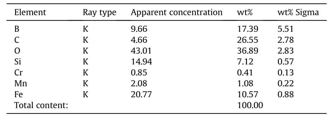
Table 5Chemical elements of the spherical phase.
(2)The radial fracture patterns of the three shells are dominated by adiabatic shear fractures,and meanwhile,accompanied by some tensile-shear fracture.The process of converging adjacent two shear fracture cells to form a step-like fracture characteristic is revealed.The effect of tempering temperature on the fracture characteristic parameters of shell wreckage including the circumferential divide size,the thickness,and the number of circumferential divisions was obtained.When the tempering temperature increased from 350°C to 500°C,the circumferential divide size increased by 11.9%,the average thickness decreased by 9.2%,and the number of circumferential divisions decreased by 16.1%.When the tempering temperature continued to increase to 600°C,the corresponding fracture feature parameters did not change significantly.
(3)The SEM investigation of the fracture morphology of the 40CrMnSiB steel shell with different tempering temperatures was conducted.With increasing tempering temperature,the flow-like structure characteristics of the fracture surface was less obvious and the amount of alloying carbide that precipitated during the tempering process increased.This increased carbide precipitation resulted in an increased number of spherical carbide particles scattered around the fracture surface.Comparing the microscopic fracture characteristics of different axial positions of the shell tempered at 350°C,it is found that the fracturing near the middle position comprises a plurality of radial shear fracture units.In contrast,the fracture at the initiation end was formed by tearing along the crack,which originated at a distance from the initiation end and propagated along the axis direction.
Declaration of competing interest
The authors declare that they have no known competing financial interests or personal relationships that could have appeared to influence the work reported in this paper.
Acknowledgment
The work presented in this paper has been funded by the National Natural Science Foundation of China(Grant No.11972018),and sponsored by the Defense Pre-Research Joint Foundation of Chinese Ordnance Industry(Grant No.6141B012858).
- Defence Technology的其它文章
- Defence Technology
- Pressure relief of underground ammunition storage under missile accidental ignition
- Mitigation effects on the reflected overpressure of blast shock with water surrounding an explosive in a confined space
- Fabrication and analysis of TIG welding-brazing butt joints of in-situ TiB2/7050 composite and TA2
- Effect of the end cap on the fragment velocity distribution of a cylindrical cased charge
- A novel DOA estimation algorithm using directional antennas in cylindrical conformal arrays

