
Fabrication and analysis of TIG welding-brazing butt joints of in-situ TiB2/7050 composite and TA2
2021-05-06 12:30:30HunhunSunYiRenYngFengHoqingDongChenChunjunXiHoweiWng
Defence Technology 2021年3期
Hun-hun Sun ,Yi-o Ren ,Yng Feng ,Ho-qing B ,Dong Chen ,Chun-jun Xi ,Ho-wei Wng
a School of Materials Science & Engineering,Shenyang Ligong University,Shenyang,China
b School of Materials Science & Engineering,Shanghai Jiao Tong University,Shanghai,China
Keywords:In-situ TiB2/7050 composite TA2 TIG welding-brazing Fabrication Analysis
ABSTRACT Lightweight hybrid structures of Al MMCs and titanium alloy dissimilar materials have great prospect in the defence industry application.So,it is necessary to join Al MMCs with Ti metal to achieve this structural design.In this work,in-situ TiB2/7050 composite and TA2 were firstly attempted to join by TIG welding-brazing technique.The result was that the intact welding-brazing butt joint was successfully fabricated.The joint presents dual characteristics,being a brazing on TA2 side and a welding on TiB2/7050 side.At brazing joint side,ER4043 filler metal effectively wets on TA2 under TIG heating condition,and a continuous interfacial reaction layer with 1-3μm is formed at welded metal/TA2 interface.The whole interfacial reaction layers are composed of Ti(AlSi)3 intermetallic compounds(IMCs),but their morphologies at the different regions present obvious distinguishes.The microhardness of the reaction layers is as much as 141-190 HV.At welding joints side,the fusion zone appears the equixaed crystal structure,and the grain sizes are much smaller than those of welded metal,which is attributed to the effect of TiB2 particulates from the melted TiB2/7050 on acceleration formation and inhibiting growth for the new crystal nucleus.The tensile test results show that average tensile strength of the optimal welding-brazing joint is able to achieve 138 MPa.The failure of the tensile joint occurs by quasi-cleavage pattern,and the cracks initiate from the IMCs layer at the groove surface of TA2 and propagate into the welded metal.
1.Introduction
The joining of two dissimilar materials is urgently required in many light weight military structure such as light combat aircraft(LCA),future main battle tank(FMBT),light combat vehicle(LCV),submarine torpedo,etc[1].Aluminum metal matrix composite(MMC)and titanium alloy are two kinds of important materials in the defence industry to reduce weight and improve properties[2-4].Lightweight hybrid structures composed of Al MMCs and Ti alloy will be required to produce many important components for military production.However,it is well known that the thermal joining of Al and Ti is rather difficult because of their large differences in the physical,chemical and metallurgical performance.These differences result in unavoidable formation of brittle intermetallic compounds(IMCs)that seriously degrade the mechanical properties of welding joints[2,5].In the recently years,many joining processes have been developed to bond aluminum alloy and titanium alloy[6-9].Thereinto,tungsten inert gas(TIG)weldingbrazing of aluminum alloy and titanium alloy butt joint has been accomplished[10].The results indicate that TIG welding-brazing has potential to inhibit the dissolution of Ti metal into the welded metal and prevent the formation and growth of brittle IMCs,and an intact joint can be fabricated by adding the filler metal.However,Al MMCs have some obvious different physical and chemical characterizations from their matrix aluminum alloy.The weldability of Al MMCs and Ti metal is not predicable,and the effective joining processes are urgent to research.
The aim of this work is to explore the fabrication technique of lightweight hybrid structures of in-situ TiB2particulate reinforced Al MMC and Ti metal.In-situ TiB2/7050 composite was synthesized by a mixed salt reaction techniques[11,12].TiB2particulates are endogenously formed in these composites,which results in many advantages such as fine reinforcements[13,14],having good bonding with the matrix,and cleaner reinforcement/matrix interface[15].The composites have more excellent mechanical properties than most aluminum alloys,such as higher strength,high elastic module,and better high cycle fatigue[14-16].So,it is greatly significant to explore the effective connection method for the applications of lightweight hybrid structures of in-situ TiB2/7050 composite and Ti metal.In this work,TIG welding-brazing was firstly employed to weld in-situ TiB2/7050 composite and TA2.ER4043 was selected as the filler metal.Fabrication process was studied,and the microstructures and mechanical properties of the welding-brazing joints were analyzed and evaluated.
2.Experimental procedure
2.1.Materials and welding-brazing process
The in-situ 6 wt% TiB2/7050 composite employed in this study was fabricated with an exothermic reaction process via K2TiF6and KBF4mixed salts.The detailed description of this process could be referred elsewhere[16].The cast composite was extruded into the ingot at 420°C with an extrude ratio of 30:1.Subsequently,the composite ingots were treated with T6 which included solution at 477°C for 50 min and water quenching at room temperature,then aging at 120°C for 20 h.Then the 200 mm×75 mm×6 mm specimens were cut from the composite ingot for the subsequent use.Fig.1(a)and(b)give the microstructures of in-situ TiB2/7050 composite at parallel and vertical to the extrusion direction,respectively.It can be seen that the grain sizes of the extruded composite are finer,and TiB2particulates mainly distribute in the interdendritic regions.SEM observation finds that the size of TiB2particulates ranges from 30 to 500 nm and their shapes are hexagonal,cubic,or spherical as shown in Fig.1(c).TA2 plates with the same size as TiB2/7050 composite were prepared as the other welding base material.The filler material was ER4043 wire of 3 mm in diameter.No flux was presented in the filler wire,and none was added externally.The chemical compositions of matrix 7050 alloy of in-situ TiB2/7050 composite,TA2 and ER4043 were listed in Table 1.Tensile properties of in-situ TiB2/7050 composite[16],TA2 and ER4043 were listed in Table 2.For the two base metals,a 30°bevel and 2 mm root face were cut on one long edge.Then,the samples were cleaned using abrasive paper and degreased with acetone.Before welding,two samples were butted together,and the groove was prepared as shown in Fig.2.
The TIG welding-brazing process was conducted using WSE-500 welding machine.The cerium tungsten electrode was used,and the diameter was 4 mm.During welding,the welding torch withtungsten electrode was fixed at an automatic travel device.In order to avoid the molten of TA2,the tungsten electrode was deviated toward to in-situ TiB2/7050 composite and the distance to the welding center was about 1 mm.The filler metal was manually feed to the welding arc zone.The schematic diagram of TIG weldingbrazing of in-situ TiB2/7050 and TA2 was presented in Fig.3.The welding current was 80-200 A,and welding speed was 1.5-2.0 mm/s with an argon gas flow rate of 10 L/min.During welding process,the welding firstly was carried out from the groove surface of the base materials.A face bead was filled up the groove,and the weld reinforcement was formed.Then the weldment was inverted,and a back bead was deposited when the top bead was cooling to about 100°C.Finally,the whole joint was completely welded.
2.2.Inspection methods
After welding,typical cross-sections of the joints were cut for fabricating the metallographic sample.Then the samples were polished to a mirror-like surface aspect and etched for 10 s in Keller’s reagent.The microstructures of the welding-brazing joints were observed by Axiovert 200 MAT optical microscope(OM)and scanning electron microscopy(SEM)with attached EDS.Vickers microhardness of the welded samples was evaluated using a FM-300 microhardness tester under the load of 5 N with a dwell time of 5 s.For every monitoring region,the measurement series comprised 5 indentations,and their average values were calculated.Tensile tests were conducted at room temperature using a WAW-600E machine at a cross-head velocity of 1 mm/min.In order to evaluate accurately the tensile strength of primary welding-brazing joint of in-situ TiB2/7050 composite and TA2,the reinforcements of the weld seams were not removed.The dimension of tensile test specimens was shown in Fig.4.After abruption,the fraction surfaces of tensile specimens were examined under SEM.
3.Results and discussion
3.1.Weld appearance
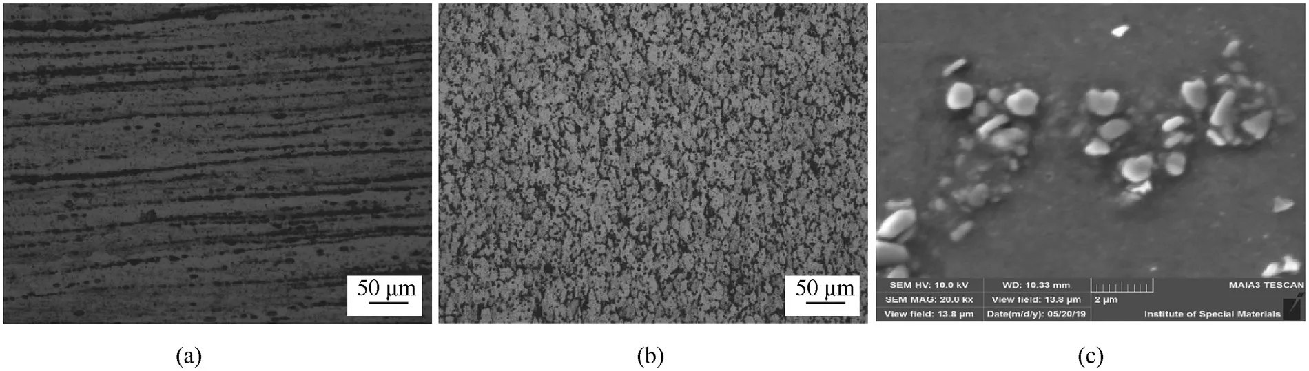
Fig.1.Microstructures of in-situ TiB2/7050 composite of(a)parallel to the extrusion,(b)vertical to the extrusion direction,(c)in-situ TiB2 particulates.
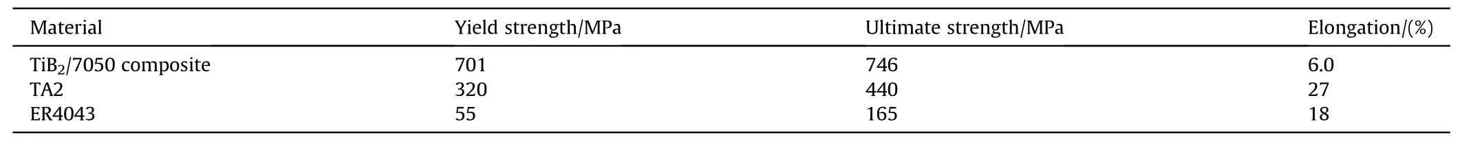
Table 2Tensile properties of in-situ TiB/7050 composite,TA2 and filler wire.
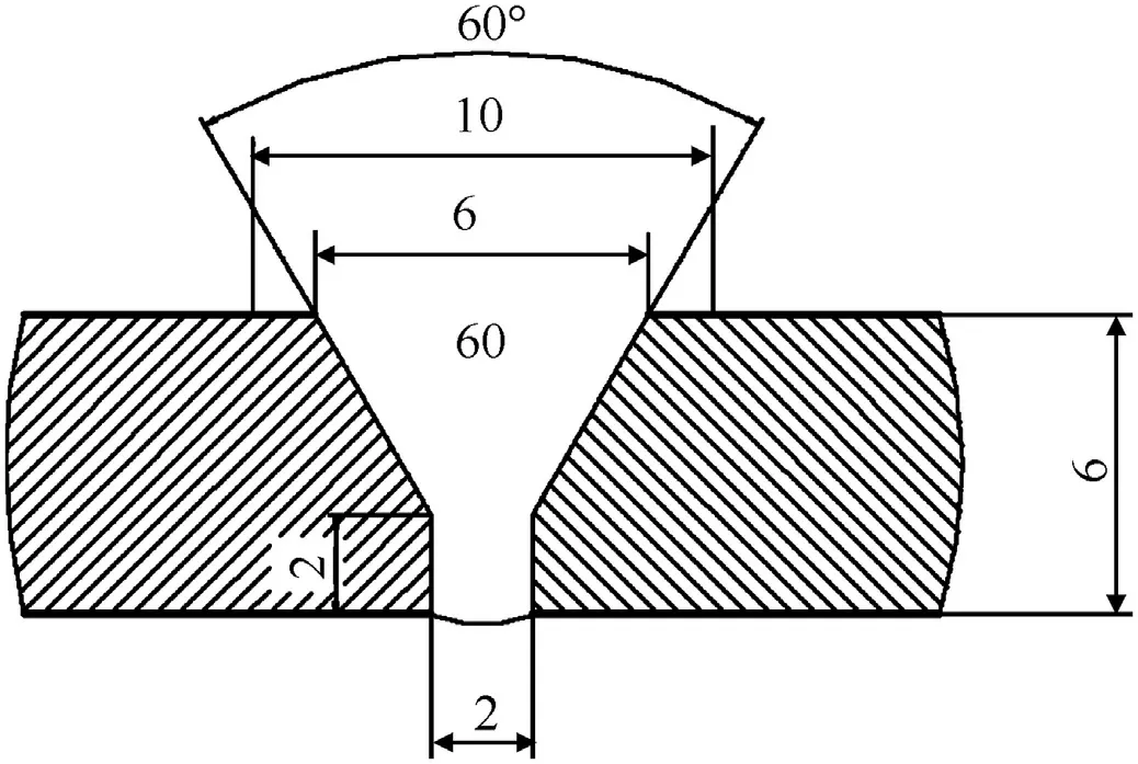
Fig.2.Schematic diagram of butted joint.
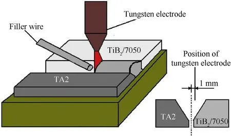
Fig.3.Schematic illustration of in-situ TiB2/7050 and TA2 butted joint welded by TIG welding-brazing.
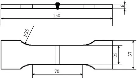
Fig.4.Dimensions of tensile test specimen.
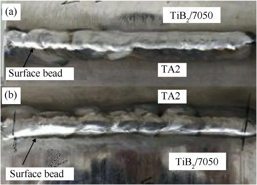
Fig.5.Typical weld appearances of welding-brazing of in-situ TiB2/7050 composite and TA2:(a)surface bead,(b)back bead.
Fig.5 presents the typical and good surface appearance of TIG welding-brazing joint of in-situ TiB2/7050 and TA2 with welding current of 150 A.It is clearly that the surface of the face bead and back bead are both smooth,and the weld width is uniform and no macroscopic defects are found.
3.2.Macrostructure and microstructure
Fig.6(a)shows the macroscopic cross-section morphology of the joint with 150 A current.Obviously,the joint exhibits a typical welding-brazing dual characteristic.TA2 does not almost melt,and it is adequately wetted by the molten ER4043 filler metal to form a brazed joint on TA2 side.In-situ TiB2/7050 composite melts and produces a typical fusion joint,and the molten composite mix with the molten filler metal to form a fusion zone.
In order to detailedly study the microstructure characteristics of the welding-brazing joint of in-situ TiB2/7050 and TA2 using ER4043 filler wire,the microstructures of several typical positions in Fig.6(a)were further observed by using OM and SEM in a magnified field,as shown in Fig.6(b)-6(f).It is obvious that the welding-brazing joint can be concretely distinguished six different zones,and they are TA2 base metal,interface zone(IZ)of TA2 and weld metal,welded seam(WS),fusion zone(FZ),heat affected zone(HAZ),and in-situ TiB2/7050 base metal,respectively.Fig.6(b)shows the interface morphology between welded seam and TA2.It is clearly observed a compact combination and no obvious melt occurs on TA2 metal.These results illustrate that the liquid ER4043 filler metal has fully wetted and spread on TA2 metal,and the interfacial reaction can be controlled during TIG welding-brazing.Fig.6(c)presents the welded metal consisted of ER4043 filler metal mainly presents equiaxed crystal microstructure,which is composed ofα-Al grains and Si phase at the intergranular zone.The equiaxed crystal structure in WS is attributed to the relatively lower cooling rate,which is due to higher heat input from a large filler metal in order to completely penetration welding for 6 mm base metal.So the microstructure morphology of the welded metal in this work is different from dendritic structure of the weld metal obtained from welding thin plate with a higher cooling rate[8].Fig.6(d)presents the microstructure morphologies of FZ and HAZ near TiB2/7050 composite.It can be found that fusion zone is also equixaed crystal structure,and the grain sizes are smaller than those of weld metal.SEM observation finds that some TiB2particulates distribute at the grain boundary of fusion zone metal,as shown in Fig.6(e).The fusion zone is formed by melting ER4043 filler wire and TiB2/7050 composite,and these fine TiB2particulates from molten TiB2/7050 composite have an important effect on fine crystal formation.Firstly,the presence of TiB2particulates decelerates the solidification front and therefore hinders the dendritic grain growth from the liquid-solid interface[17].Secondly,TiB2particulates also add heterogeneous nucleation to the solidification process[17,18].Obviously,the size of equixed crystal structure in HAZ is bigger than that of TiB2/7050 composite base metal,which is attributed to the grain growth due to heating of weld metal during welding.Fig.6(f)shows the clear morphology of the adjacent zone between face bead and back bead.It can be seen that the grain sizes of face bead metal and back bead metal are substantially identical.Additionally,a few of porosities are observed in WS and FZ.It is difficult to completely relieve the porosities for TIG joint of aluminum metal.

Fig.6.Macrostructure and microstructures of TIG welding-brazing joint with 150 A current:(a)macroscopic cross-section,(b)microstructure at the IZ(taken in the area marked by rectangle B in Fig.6(a)),(c)microstructure at WS(taken in the area marked by rectangle D in Fig.6(a)),(d)microstructures at FZ and HAZ(taken in the area marked by rectangle E in Fig.6(a)),(e)SEM image of FZ,(f)microstructure at the adjacent zone between face bead and back bead(taken in the area marked by rectangle F in Fig.6(a)).
3.3.Intermetallic compounds layer
Interfacial reaction layers of the brazing joint have the most critical effect on the mechanical properties of a TIG weldingbrazing joint[19].So the interfacial microstructure images of SEM at the different locations in the same joint of Fig.6(a)were further observed and analyzed.Fig.7(a),7(c)and 7(e)are corresponding to the zones marked with rectangular A,B and C in Fig.6(a),respectively.At top surface of TA2(Fig.7(a)),the thickness of the interfacial reaction layer is about 3μm.The reaction layer includes two structures,the bottom layer is the dense lamellar structure and the top layer is the celluar structure.At groove surface(Fig.7(b)),the interfacial reaction layer is thinner and only 1μm,and presents a lamellar structure almost without any bulging.At underside of TA2(Fig.7(c)),the thickness of the interfacial reaction layer is also approximately 3μm,but their morphologies is completely dissimilar with those formed on the top surface and shows a thick lamellar structure with bulging.During welding-brazing,the compositions of molten pool are mainly Al atoms and a little of Si atoms,and there are a small amount of Ti atoms enriched at the interface of TA2 side.As the solidification of molten pool,a large constitutional supercooling is generated by a high concentration of Ti atoms at the interface.Ti3Al,TiAl,TiAl2and TiAl3will take priority to be formed in proper order.Finally,TiAl3as a major phase is formed due to its high reaction enthalpy(ΔG)[2].Simultaneously,Si has a great retardation effect on the Ti/Al reaction,and proposed that this effect is due to several mechanisms that involve diffusion and incorporation of Si into the growing TiAl3phase[20].According to Zhu’s study,Si atoms have a clear preference to substitute Al atoms due to the energy stabilization effect[21].The TiAl3phase can dissolve Si up to 12.5-18.75 wt%,and become Ti(Al,Si)3phase[2].According to the EDS analysis results from the different interfacial position in Fig.7(b),(d)and 7(f),in the IMCs the atomic ration of Ti and sum of Al and Si is approximately 1:3,and the content of Si is about 6.0-9.0%.So it is deduced that all Si atoms can dissolve into TiAl3.It can be concluded that all these IMCs are Ti(Al,Si)3phase.
It is well known that heating effect plays an important role in the morphology of interfacial reaction layer.According to the macrostructure morphology of the welding-brazing(Fig.6(a)),it is obvious that the molten metal that contacted with top surface and under surface of TA2 metal are abundant,and the losing heat of those molten metal is lower than those that contacted with the groove surface.So it is deduced that the effect of molten metal on the top surface and under surface is higher than that on the groove surface,which is the reason that the distinguished morphologies IMCs generated at the different regions.At the groove surface,heat time of TIG arc is relatively short,and a large amount of heat from molten metal is dispersed by cold TA2 metal.The result is that the quantity of Ti atoms dissolved into weld metal is relatively smaller.The IMCs nucleate parallel to the interface of the welded metal and TA2,and their formation is mainly controlled by interface reaction mechanism.So the thinner lamellar IMCs without bulging are produced.At the top surface,the heat time of TIG arc is longest,and the growth of IMCs is mainly controlled by diffusion.The more molten weld metals lead to the dissolutions of more Ti atoms.The dense lamellar IMCs firstly form.Subsequently some of them will preferentially grow as celluar structure.At the under surface,dissolutions of Ti atoms are also numerous due to heating of back bead metal.But the temperature gradient at the interface front of TA2 and molten pool is lesser,which is affected by remaining temperature of the surface bead.So the thick lamellar IMCs are generated.Additionally,a little of Ti(AlSi)3can be separated from the interface and enter into molten pool as a result of molten pool stirring.Some rupture rod-shaped IMCs are observed in the vicinity of the reaction layer,as shown in Fig.7(a).
3.4.Effects of heat input on weld formation
In this work,the effects of heat input on the welding-brazing performances were investigated by changing the welding current.The characteristics of the joint fabricated from the optical welding current of 150 A have been revealed by above investigations.The weld formations of the joint obtained from other welding currents are studied as following.
When the heat input(90 A welding current)is lower,the liquid filler metal spreads on the TA2 surface,but does not completely wet all the whole TA2 metal,as shown in Fig.8(a).Along with solidification shrinkage of the weld metal,a gap appears between TA2 and welded seam.Fig.8(b)is the SEM images of the rectangular location in Fig.8(a).The welding-brazing joint is prone to crack at high loads.
When the welding current is increased to 190 A,a crack section appears at the TA2 aside,as shown in Fig.9(a).The crack generates and expands along the interface between TA2 metal and weld metal,as shown in rectangular location of Fig.9(a),and causes the dehiscence of the weld metal.Moreover,it can be seen that TA2 groove has been seriously molten,and huge IMCs are formed and grow toward to the weld inner,as shown in Fig.9(b).At the center of the welded seam,some acicular IMCs are found,and the reason is that a lot of Ti atoms dissolve into the liquid Al alloy and acicular IMCs form in the welded metal.Simultaneously,at fusion welding aside some long cracks are observed at the HAZ of in-situ TiB2/7050 composite,which is caused by the stress that brought by the expansion and shrinkage during welding.
3.5.Mechanical properties
According to the above test results,it is noticeable that the welding-brazing joint of in-situ TiB2/7050 and TA2 made with welding current of 150 A presents excellent weld appearance,and is hardly cracks and incomplete fusion.So it is selected as the measurement samples for the microhardness and tensile strength in the following studies.
3.5.1.Hardness
According to the microstructure characteristics of the weldingbrazing joint between in-situ TiB2/7050 and TA2,the microhardness of some typical regions are measured and recorded.The schematic presentations of measurement positions corresponding to real morphology of Fig.6(a)are showed in Fig.10(a),and the microhardness values at the different regions are indicated in Fig.10(b).The microhardness of TA2 metal(regions 1)and TiB2/7050 composite(region 10)are significantly higher than that of welded seam.The welded seam was divided into upper,middle,lower regions(region3,5,7),measurement results indicate that the micrhardness of each region is nearly identical,varying from 83 HV to 84 HV.The microhardness of IMCs layer at the TA2 upper side(region 2),corresponding to real morphology of Fig.7(a),is to 186 HV.The microhardness of IMCs layer at the groove face of TA2(region 4),corresponding to the lamellar structure of Fig.7(b),is 141 HV.The microhardness of IMCs layer at the TA2 lower side(region 6),corresponding to rugged structure of Fig.7(c),is even up to 190 HV.Overall,the microhardness of the IMCs is not only higher than that of weld metal but also higher than two base metals.The average microhardness of fusion zone near to TiB2/7075(region 8)is 106 HV,which is higher than that of weld metal due to its finer grains and dispersion strength of TiB2particulates from TiB2/7050 base metal.However,at HAZ(region 9)the mirohardness(121 HV)is lower than that of TiB2/7050 base metal,which is attributed to the grain growth.
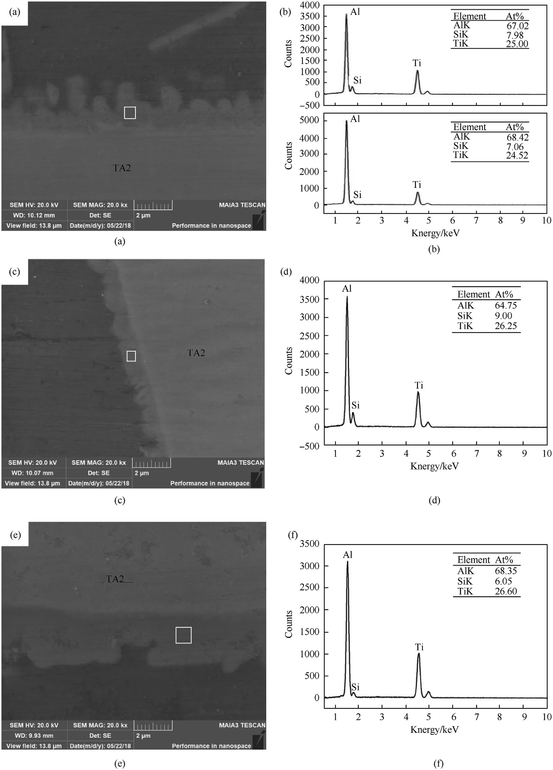
Fig.7.Microstructures of interfacial reaction layers and corresponding EDS analysis results marked by rectangles A,B,C in Fig.6(a):(a),(c),(e)magnified micrographs and(b),(d),(f)corresponding EDS results of regions taken from the areas.
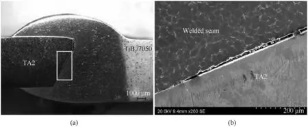
Fig.8.Typical morphologies of welding-brazing joint under welding current of 90 A:(a)macroscopic cross-section,(b)microstructure at the interfacial zone(taken in the area marked by rectangle in Fig.8(a)).
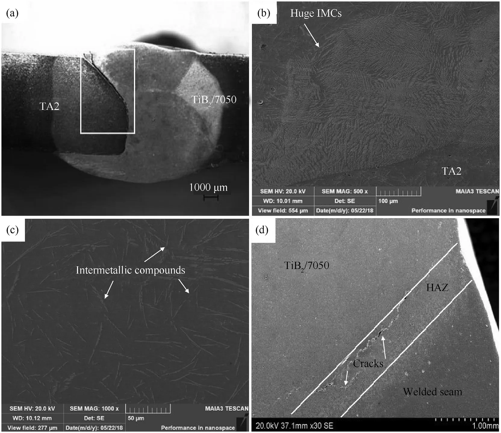
Fig.9.Typical morphologies of welding-brazing joint under welding current of 190 A:(a)macroscopic cross-section,(b)huge IMCs at IR,(c)acicular IMCs in WM,(d)cracks in HAZ.
3.5.2.Tensile strength and fracture behavior
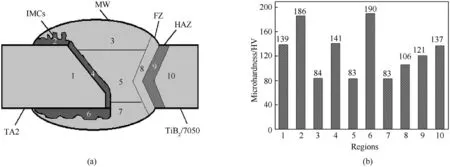
Fig.10.Microhardness results:(a)schematic presentations of measurement positions,(b)microhardness value at the different regions.
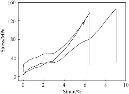
Fig.11.Tensile stress-strain curves for welding-brazing joint of in-situ TiB2/7050 composite and TA2 under welding current of 150 A.
In order to get an accurate tensile strength,three tensile specimens were cut off from the welding-brazing test plate of in-situ TiB2/7050 composite and TA2.Fig.11 gives three stress-strain curves obtained from tensile tests for the welding-brazing joints.Observing these curve features,it is known that three weldingbrazing samples reach their ultimate tensile strength(131 MPa,139 MPa and 145 MPa),then rapidly occur fracture.Average tensile strength of the welding-brazing joint is approximately 138 MPa which is much lower than those of base metal and filler metal.Further,the fracture morphologies of the joint are observed.Fig.12(a)is the cross-section photo of typical fractured samples.The different regions of the fracture face are further analyzed under SEM.Fig.12(b)is the image of the fracture face(A of Fig.12(a))at TA2 aside,and the surface is very flat.EDS analysis confirms that it is groove surface of TA2 metal.Fig.12(c)is the image of the fracture face(location B of Fig.12(a))at weld metal aside,and the surface is coarse.The cleavage steps can be served clearly on the surface,and there are some secondary cracks,which indicate that it is a typical brittle fracture feature.EDS analysis shows that a lot of Ti(AlSi)3phase existed on the fracture face according to the atomic ratio of Ti,Al and Si.According to above study results,IMCs occur at the interfacial layer of TA2 and weld metal,where the stress concentration is maximal due to the root geometry[10].The Ti(AlSi)3phase,with a tetragonal DO22structure[22],is characterized by extreme brittleness and becomes a source of internal mirocracks originating during loading.So the crack initiates from the reaction layer close to TA2 metal and extends into the bilateral welded seam.Then the weld metal is also abrupt.Fig.12(d)is the fracture morphology the weld metal(location C of Fig.12(a)),which presents the dimple rupture pattern due to the good plasticity of weld metal.Simultaneously,it is worthy to mention that the welding joint on in-situ TiB2/7050 side is still intact after tensile test.The reason is attributed to the fine structures and reinforcement effect of TiB2particulates.
4.Conclusions
In this study,TIG welding-brazing process was successfully used to join the butt dissimilar material of in-situ TiB2/7050 composite and TA2 by using ER4043 as filler wire.The conclusions are summarized as follows:
(1)ER4043 filler metal effectively wets and spreads on TA2 under proper TIG heating condition,resulting in a brazing combination at TA2 metal side.A continuous IMCs layer with 1-3μm is formed at the interface of TA2 and welded seam.At the top,groove surface and bottom interfacial area of TA2 metal,IMCs layers present the celluar,lamellar,and rugged structures,respectively.These IMCs with different morphologies are both Ti(Al,Si)3phase.
(2)At in-situ TiB2/7050 composite aside,a great welding joint is obtained.The fusion zone presents fine equixed crystal structure.The reason is that TiB2particulates from the melted composite play an important role to accelerate crystal nucleus formation and inhibit crystal nucleus growth.
(3)The optical tensile strength of welding-brazing joint of insitu TiB2/7050 and TA2 is up to 138 MPa.During tensile test,the welding joint at TiB2/7050 composite side is tough and the failure occurs at brazing joint at TA2 side.The cracks initiate from the interfacial reaction layer and propagate into the welded metal.
Declaration of competing interest
We declare that we have no financial and personal relationships with other people or organizations that can inappropriately influence our work,there is no professional or other personal interest of any nature or kind in any product,service and/or company that could be construed as influencing the position presented in,or the review of,the manuscript entitled.
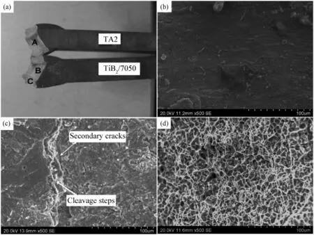
Fig.12.Fracture morphologies of the welding-brazing joint:(a)fracture macroscopic morphology,(b)fracture microscopic morphology on TA2 surface,(c)morphology of IMCs layer on the weld metal surface,(d)fracture microscopic morphology of weld reinforcement metal.
Acknowledgements
This research is supported by Basic Science Research Project of Colleges and Universities in Liaoning Province in China(No.LG201714).
- Defence Technology的其它文章
- Defence Technology
- Pressure relief of underground ammunition storage under missile accidental ignition
- Mitigation effects on the reflected overpressure of blast shock with water surrounding an explosive in a confined space
- Effect of the end cap on the fragment velocity distribution of a cylindrical cased charge
- A novel DOA estimation algorithm using directional antennas in cylindrical conformal arrays
- Research on the intermediate phase of 40CrMnSiB steel shell under different heat treatments