
Mitigation effects on the reflected overpressure of blast shock with water surrounding an explosive in a confined space
2021-05-06 12:30:32HiinXuLongkuiChenDezhiZhngFngpingZhngZhowuShenWenxingLiuShenghongHung
Defence Technology 2021年3期
Hi-in Xu ,Long-kui Chen ,De-zhi Zhng ,Fng-ping Zhng ,Zho-wu Shen ,Wen-xing Liu ,Sheng-hong Hung ,*
a CAS Key Laboratory of Mechanical Behavior and Design of Materials,University of Science and Technology of China,Hefei,230026,China
b Northwest Institute of Nuclear Technology,Xi’an,710024,Shanxi,China
Keywords:Shock Water mitigation Scaled distance Water-to-explosive weight ratio Confined container
ABSTRACT The mitigation of blast shock with water has broad application prospects.Understanding the mitigation effects on the reflected overpressure of the explosion shock with water surrounding an explosive in a confined space is of great significance for military explosives safety applications.To estimate the effects of the parameters on the reflected overpressure of blasted shock wave,a series of experiments were carried out in confined containers with spherical explosives immersed in a certain thickness of water,and numerical simulations were conducted to explore the corresponding mechanisms.The results reveal that the reflected overpressure is abnormally aggravated at a small scaled distance.This aggravation is due to the high impulse of the bulk accelerated water shell converted from the explosion.With increasing scaled distance,the energy will be gradually dissipated.The mitigation effects will appear with the dispersed water phase front impacting at a larger scaled distance,except in the case of a dense water phase state.A critical scaled distance range of 0.7-0.8 m/kg1/3 for effective mitigation was found.It is suggested that the scaled distance of space walls should be larger than the critical value for a certain water-to-explosive weight ratio range(5-20).
1.Introduction
Mitigating a shock wave by immersing explosives under a water layer with an appropriate thickness is an effective method for alleviating the damage of an explosion.This method has been widely researched in studies of defence explosives safety regime during the past several decades[1-7].This method can reduce the danger zone around the location where the explosives are stored and increase the storage capacity of the explosive storage facilities.Water barriers such as water walls have the advantages of convenient construction,low cost and strong mobility,endowing this approach with broad application prospects.
Keenan et al.[1]verified the feasibility of using a water wall to prevent explosions in an explosive storage cell room in an experimental study of the quasi-static pressure and impulse change of the explosion before and after the water walls placement.They found that a pressure drop of 90% was attained after water placement.Chabin et al.[2]conducted a series of experiments to study the relationship between the free-field pressure and impulse at the scaled distance between explosive and water wall of not less than 1 m/kg1/3.Hansson et al.[3]studied the quasi-static pressure variation at different axial distances of the KLOTZ-Club tunnel before and after placing 2 t of water around a 1 t TNT equivalent cannonball in a full-scale experiment.Malvar et al.[4]placed water bags around the explosives in vessels for ammunition destruction and obtained a 70%reduction in the quasi-static peak gas pressure.Absil et al.[5]conducted parametric experiments to investigate water mitigation of explosion effects.Kirkpatrick et al.[6]compared the mitigation performance of several structurally weak materials in a mitigation research programme aimed at developing a predictive capability.Mao et al.[7]conducted the experiments on shock wave mitigation with water walls,while Cheng et al.[8]numerically investigated the mitigating effect of a water wall on the generation and propagation of blast waves of a nearby explosive using DYTRAN.Li et al.[9,10]studied the effect of the distance between the water wall and the explosive on the incident shock wave and its impulse experimentally and with numerical methods.Zhao[11]carried out a numerical simulation study of the water mitigation effects in a closed space based on the experiments conducted by other researchers.Bornstein et al.[12-15]carried out a series of works on near-field blast mitigation with fluid containers.
Among the above described works,with the exception of the works Kirkpatrick et al.[6]and Cheng et al.[8],most previous studies have focused on the influence of water placement on the quasi-static gas pressure in a large space or on the free-field pressure at a large scaled distance.Kirkpatrick et al.[6]have observed that the momentum acquired by the mitigant has the potential to cause significant near-field damage particularly for water material by measuring both the reflected pressure and impulse of the nearfield loading at a scaled distance of 0.25-2.5.However,they did not explain the mechanism underlying this effect.Cheng et al.[8]numerically computed the peak overpressure and impulse variation for cases with and without air-gap for a scaled distance range of 0.5-10.However,their work focused on the mitigation effects comparison and did not investigate the complex multiphase interaction process of shock,water and air.In summary,the influence and the underlying mechanism of the effect of water on a shock wave propagating under the conditions of small scaled distances(<1 m/kg1/3)are still unclear due to difficulties involved in the measurements and observations.In fact,this mechanism may involve more complex multiphase interactions of shock,water and air.The detailed mechanism is not yet fully understood,and the design parameters for the mitigation in small confined space storage of explosive are unknown.
In this work,a series of experiments using a spherical explosive immersed in different amounts of water were performed in vessels with different geometries under the condition of small scaled distances.The reflected overpressures on the inner wall of the vessels were measured.The effects of the ratio of the water mass to explosive TNT equivalent mass(water-to-explosive weight ratio)and scaled distance on the reflected overpressure were studied.The mechanism of water mitigation of explosion shock wave at different water-to-explosive weight ratios and scaled distances was analysed and explained based on both experimental and numerical results.
2.Experimental setup
Fig.1 shows the experimental setup of the explosion test with the explosive immersed in water.Three vessel geometries were used,specifically,a cylindrical vessel(Fig.1(a)),a spherical vessel(Fig.1(b))and a cubic vessel(Fig.1(c)).The inner diameter of the cylindrical vessel is 200 mm,and its axial length is approximately 1 m;the inner diameter of the spherical vessel is 523 mm,and the inner side length of the cubic vessel is 500 mm.Due to the geometry scale difference,the scaled distance can be adjusted more conveniently.The test cases performed with different relevant parameters are listed in Table 1.
In the experiments,composition B is the explosive actually adopted in experiments,which is made by Xi’an institute of modern chemistry of China with TNT equivalent is 1.32[16].Overall,60,10 and 1 g TNT equivalent explosives were used as explosion sources,respectively.60 g and 10 g TNT equivalent explosives are composed of a 1 g TNT equivalent priming pill and a spherical main explosive.The 1 g TNT equivalent priming ball is detonated at the centre by a flexible detonator capsulated with lead.The detonator has a diameter of 1 mm and a linear charge density of 0.5 g/m RDX.Fig.2 shows the diagram of the setup of the water,spherical container shell,explosive and detonator.In this design,the explosive source should be placed in the centre of the spherical container shell.The container shell is made of low tensile strength material such as polyvinyl chloride plastic(PVC)or glass.Due to the differences in the strength and density,the wave impedance of the glass shell is relatively larger than that of the PVC shell,but the PVC shell thickness of 0.18 mm can be obtained,while for the thickness of the glass shell is limited to only 0.5 mm.Thus,each material has its advantages and disadvantages.In tests,only the cases at a scaled distance of 1.21 m/kg1/3(cases 9-11)used the PVC shell.In any case,for both shells,the ratio of the shell thickness to the diameter of the water sphere for all conducted tests is very small,and the mass of the spherical shell itself is negligible compared to the mass of the water sphere.In addition,the tensile strength of both materials(<50 MPa)is very low compared with the strength of explosion shock(~GPa).These characteristics ensure that the influence of the spherical shell on the experimental results can be neglected.
In cylindrical vessels,a pressure bar system with a length of 0.5 m was devised in the blasting torus as shown in Fig.1(a).The technique of measuring the reflected blast wave pressure by thepressure bar for a small scaled distance was proposed and demonstrated to be effective by Zhang et al.[17].The pressure bar is a slender elastic steel rod with a diameter of 8 mm.A 1D elastic stress wave will be generated when the explosive blasting shock wave acts on one end of the bar.By measuring the strain near the middle position of the pressure bar,the pressure of the blasting shock wave acting on the end of bar can be obtained according to the one-dimensional stress wave theory.The measuring range of the pressure bar is approximately 1200 MPa,and the upper limit of the working frequency is approximately 115 kHz.The distance between the measuring point and the explosion centre is 100 mm,and the scaled distance is approximately 0.255 m/kg1/3.
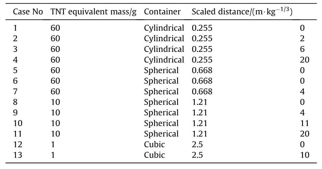
Table 1Experimental parameters.
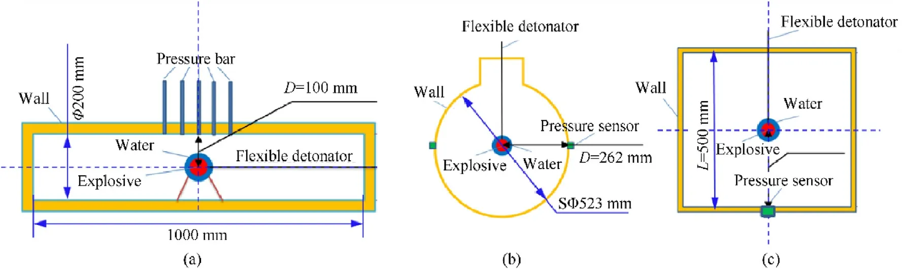
Fig.1.Schematic illustrations of the experimental setups:(a)cylindrical vessel;(b)Spherical vessel;(c)Cubic vessel.
Fig.2.Spherical explosive immersed in water.
In spherical and cubic vessels,piezoelectric pressure sensors were fixed on the wall surface of the container by flush mounting to measure the reflected overpressure of the shock wave on the inner wall of the vessel.The explosive in the spherical vessels was 60 g and 10 g TNT equivalent and the scaled distances were 0.668 m/kg1/3 and 1.21 m/kg1/3,respectively.The explosive in the cubic vessel was 1 g TNT equivalent,and the scaled distance was 2.50 m/kg1/3.
3.Numerical models and methods
Due to the potential explosion damage to instruments and complex multiphase flow field during the mitigation process,only pressure histories were obtained experimentally.To further investigate the mechanism of the mitigation effects,numerical simulations were also conducted for some experiments.The numerical simulations were carried out with the AUTODYN software using the coupled Eulerian and Lagrangian solver.
According to the symmetry characteristics of the container configuration and the explosive installation,the three container cases were investigated in 2D simulations using an axial-symmetry setup as shown in Fig.3.
The explosive,air and water were modelled in the Eulerian domain.The air was described using the ideal gas equations of state(EOS),as given by
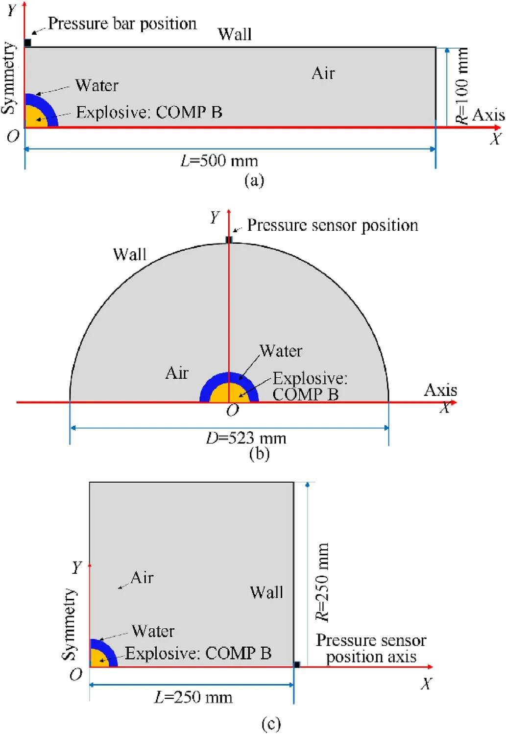
Fig.3.Computational domain and models of numerical simulations for(a)cylinder container;(b)spherical container;(c)cubic container.

whereeis the specific and internal energy of air,J/kg,pis the density of air,kg/m3,andγis generally equal to 1.4.The material parameters of the ideal gas EOS for air are listed in Table 2[18].
A Jones-Wilkins-Lee(JWL)equation of state was used to describe the explosive.The COMP B material model was used.The JWL EOS used for the COMP B is given by:
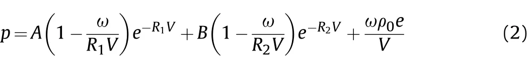
wherepis the pressure,MPa,Vis relative volume,m3,andA,B,R1,R2,andωare constants,with the values of these coefficients listed in Table 3[18].
A polynomial equation of state is used for water,and as given by
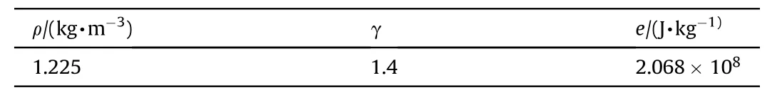
Table 2Material parameters of ideal gas EOS for air.
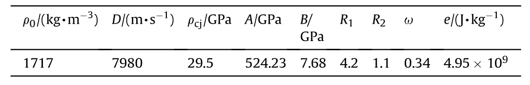
Table 3Material parameters and coefficients in the EOS for COMP B.
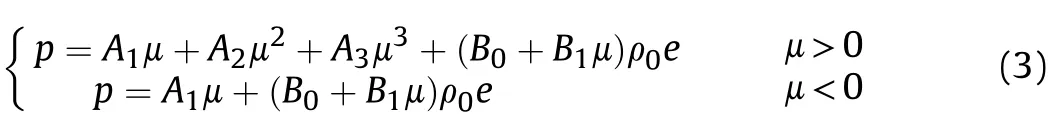
whereμ=ρ/ρref-1;A1,A2,A3are the EOS constants.The material parameters of the polynomial EOS for water are listed in Table 4[18].
It is worth noting that water is a kind of fluid material that can’t endure tensile stress.When shock is propagating through water/air interface,the reflecting shock will induce tensile stress on interface,then a kind of phenomenon called spallation will occur on water/air interface.For fluid material,the process is more complex than solid material,since many phenomena such as Richtmyer-Meshkov(RM)instability,atomization,evaporation,etc.,also occur concomitantly.So most previous numerical works chose to ignore the spallation treatment by just using the polynomial EOS without failure model as Cheng et al.did[8].In present investigation,both kinds of water models are used,one is same with previous works,i.e.,using the polynomial EOS(Eq.(3))without failure rule(called“model 1”hereinafter),the other is using the same polynomial EOS(Eq.(3))with failure rule(called“model 2”hereinafter).The failure rule for“model 2”is to set the minimum of pressure for water.In present investigation,this value is set as-100 kPa,which is chosen based on a validation of the case with water-to-explosive weight ratios of 6 at the scaled distances of 0.255 m/kg1/3.
A mesh dependence examination for the selected models and parameters was performed with different mesh sizes in the scaled distance range of 0.255-2.5 in the present study.The experimental reflected overpressure values for cases without water placement were compared with numerical predictions as shown in Fig.4.It is clear that the prediction accuracy is generally promoted by mesh refinement.For cases with the uniform 0.5 mm mesh size,the prediction accuracy is high in the entire computed scaled distance range while for cases with the large mesh size of 5 mm,a relative large discrepancy is obtained for the small scaled distance region(0.2-0.8)and the large scaled distance region(1.5-3).The accuracy of the cases with mixed mesh size(0.4-5 mm)is between those of the other two cases and is obtained by local refining of the mesh size in the zone of the explosive and its contiguity zone.In present simulations,the mesh arrangement of the uniform 0.5 mm mesh size is adopted.
It should be noted that due to the limitations of the software models,the breakup,atomization and dispersion of water droplets is not simulated directly in numerical studies;however,it is indicated by the variation of the obtained volume fraction of water.For example,zones with the volume fraction of water equal to unity represent the bulk water phase,while the zones with the volume fraction of water smaller than 1 represent the dispersed water droplets phase.
Table 4Material parameters of polynomial EOS for water.
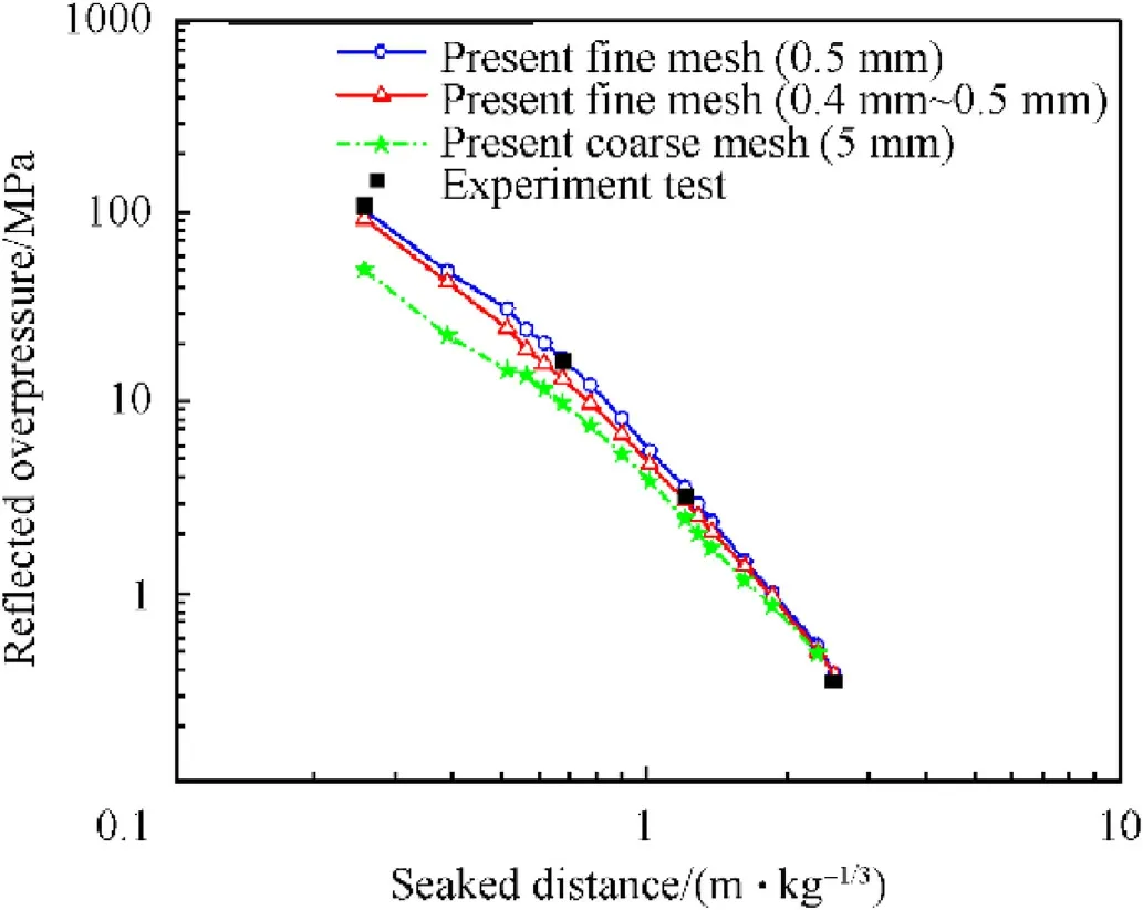
Fig.4.Mesh dependence examination with different mesh sizes for cases of the waterto-explosive weight ratio 0 for the scaled distances of 0.255-2.5 m/kg1/3.
4.Results and discussion
Fig.5 shows both the experimental and numerical results for the water-to-explosive weight ratios of 0 and 6 at the scaled distance of 0.255 m/kg1/3.
The experimental pressure curves shown in Fig.5(a)were obtained using a pressure bar system,while the numerical pressure curves were obtained by monitoring the pressure at the point corresponding to the bar installation position.It is observed that the magnitudes of three pressure curves are consistent while some discrepancy is found in the sharpness and fluctuation of wave pulse.It is clear that the numerical simulations obtained a sharper and more fluctuated pressure shock pulse than that observed in the experiments;this outcome is most likely caused by the response characteristics of the pressure bar system since the pressure shock signal obtained by the pressure bar is recovered from the stress/strain response signal,some high frequency pressure fluctuation will be smoothed(The working frequency of pressure bar is about 115 kHz).However,this kind of discrepancy doesn’t influence the prediction of peak overpressure.
An examination of Fig.5(a)clearly shows that the reflected overpressure increases significantly with water placement at a scaled distance of 0.255 m/kg1/3,and the peak value is approximately eight time greater than that without water,implying the aggravation of explosion damage.Numerical results with both models confirm these results as shown in the same plots.Comparison with experimental results shows that the overpressure peak values of numerical simulations are in good agreement with those of the experiments for the cases of both with and without water placement.We note that some negative impulse and oscillation waves with high amplitude appear in the later stage of the measured pressure histories with water placement,which may be due to the vibration of the pressure bar when impacted by the breaking up water,while the numerical simulation do not consider this effect.
Fig.5(b-d)show the material location,water volume fraction and velocity magnitude evolution,respectively,for the water placement case of numerical simulations with both water models.According to contours of model 1,at the current scaled distance,spherical water wrapped the explosive is still maintained as an unbroken water shell and is accelerated to approximately 1000 m/s when it moves to the position of the pressure bar so that the bulk of accelerated water is impacted on the wall of pressure bar,inducing overpressure that is several times greater than that of the case without water due to the higher density of water.It is clear that the magnitude of overpressure is consistent with the dynamic pressure(~500 MPa)of accelerated water.
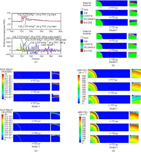
Fig.5.Experimental and numerical results for the water-to-explosive weight ratios of 0 and 6 at the scaled distance of 0.255 m/kg1/3.(a)Pressure histories comparison of the monitoring point;(b)Material location distribution at three moments before impact,at impact,and after impact of water;(c)Volume fraction of water at the same three points in time;(d)Velocity magnitude distribution at same three points in time.
For contours of model 2,the situation is some different that the spherical water shell is maintained as nearly broken state rather than continuum state in contours of model 1.The water phase is distributed in a thicker shell space with the front in more dispersed state and the bulk close to continuum,which is reasonable in consideration of spallation process of water when explosion blast wave propagating across the water/air interface.It is important to note that an approximately 100 MPa pressure trace occurred at 710 μs for experimental curve of this case in Fig.5(a),which is successfully captured by numerical simulation with model 2.The corresponding mechanism should be the state that the water phase front mainly consisting of dispersed water from spallation is firstly impacted with pressure bar as shown in contours of model 2 at t=713μs in Fig.5(b-d).However,the time of the second overpressure peak predicted with model 2 is obviously earlier than that of experiment.The reason may lies in void treatment of space between spallation water and the bulk.Fig.6 presents high-speed video images of near-field explosion with spherical explosive and water placement(60 g TNT equivalent explosive and water/explosive weight ratio of 8)measured in open space.It is clear that the process is really more complex than prediction of model 2,the space of spallation zone should be filled with droplets,vapour,air mixture produced by many concomitant phenomena such as RM instability,atomization,evaporation,etc..Obviously,void treatment of space in spallation zone will over-accelerate the bulk water layer in initial stage due to larger pressure difference around bulk water,leading to earlier prediction of second peak and thus a little over predicted overpressure peak as indicated in Fig.5(a)also.In later stage,the void space will induce series of rarefaction waves to unload the forward transmitted shock wave,resulting in underprediction of its overpressure.This phenomenon will be observed in cases at larger scaled distance as shown in Figs.7 and 8.
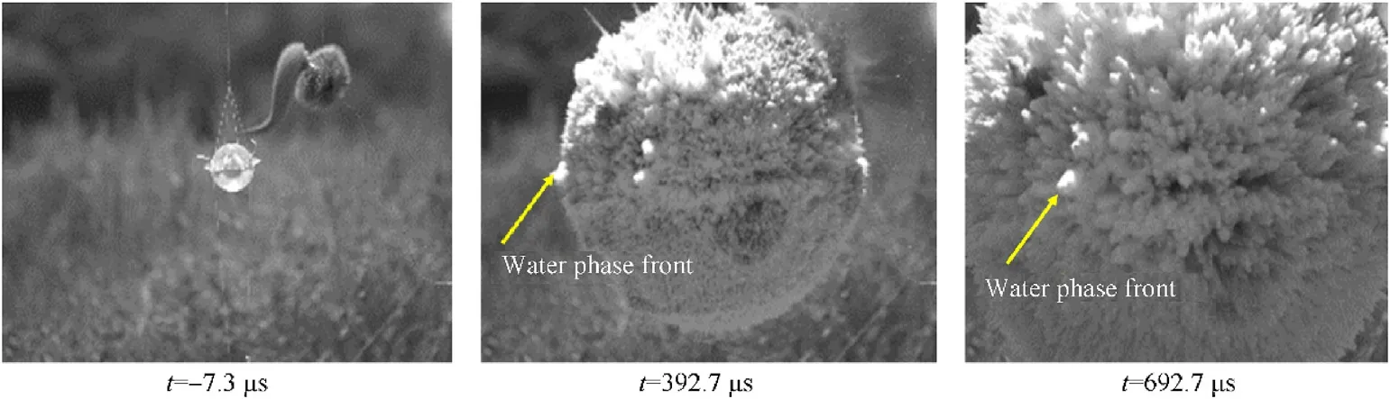
Fig.6.High-speed video images of near-field explosion with 60 g TNT equivalent spherical explosive and water/explosive weight ratio of 8 in open space.
It is worth note that although the numerical simulation with model 1 failed to predict spallation and thus the first pressure trace,it successfully predicted the overpressure peak induced by bulk water layer.These results indicated that the main part of the bulk water layer contains most of the impulse converted from the explosion shock during near-field loading when the water layer is not fully broken up.
Fig.7 further shows both the experimental and numerical results for the cases of the water-to-explosive weight ratios of 0 and 4 at a scaled distance of 0.668 m/kg1/3.Fig.7(a)shows the numerical and experimental reflected overpressure histories curves comparing the cases with and without water.We note that the experimental pressure histories for these two cases were obtained using piezoelectric pressure sensors.The pressure histories of the case without water placement are remarkable similar to each other,indicating that both experiments and numerical simulations were appropriate.It is observed that with increasing scaled distances,the peak value of the reflected overpressure decreased for both cases.For the case without water,the first peak value of the reflected overpressure is approximately 15 MPa,while for the case with water it is approximately 10 MPa.Approximately 30% of the peak overpressure is mitigated.Obviously,the first peak of case with water should be induced by transmitted shock,the numerical simulation with model 1 accurately predicted this peak while the numerical simulation with model 2 accordingly under-predicted this value.However,it is noted that in the next few tens of microseconds,an increasing fluctuated peak pressure of 17.6 MPa occurs,while in numerical simulation with model 1,a single peak of 40 MPa also occurs at almost the same corresponding point in time while in numerical simulation with model 2,an increasing peaks from 5 MPa to 12 MPa occurs at similar time point.The mechanism underlying this effect is indicted by the material location,volume fraction and velocity evolution contours of numerical simulation with model 1 for the water placement case as shown in Fig.7(b-d).The second peak for the water placement case is caused by the impacting of water and gas mixture with higher volume fraction of water.It is important to be point out that since the numerical simulation with model 1 is not included spallation,water phase is less dispersed than case with model 2,a higher local water volume fraction will be attained in water phase front,resulting in the second overpressure peak of 40 MPa.While for the corresponding state in the experimental case and numerical simulation with model 2,the water will be broken up into drops due to spallation,instability and viscous friction with larger drops following small drops in the movement,resulting in an increasing fluctuation second overpressure peak physically.
Fig.8 shows both the experimental and numerical results for the cases of the water-to-explosive weight ratios of 0 and 11 at the scaled distances of 1.21 m/kg1/3.Fig.8(a)shows the numerical and experimental reflected overpressure history curves comparison for the cases with and without water.The pressure histories of the cases with and without the water placement also show good agreement with each other except for numerical case with model 2,which seriously under-predicted the transmitted shock wave strength.It is observed that with the further increase of the scaled distances,the peak value of the reflected overpressure is strongly decreased for both cases.For the case without water,the first peak value of the reflected overpressure is approximately 3.2 MPa,while for the case with water it is approximately 1.2 MPa.Approximately 60% of the peak overpressure is mitigated because for a larger scaled distance,not only a greater fraction of the energy of the explosion shock wave is converted into the kinetic energy and internal energy of the water,but the transmitted shock will further be mitigated due to further expansion in spherical space.As shown by the velocity contours of case with model 1,due to energy transfer,the velocity of the gas and water mixture when impacting on the wall is less than 200 m/s,and the volume fraction of water is less than 0.2,so that only a very limited overpressure can be induced.
Fig.9 shows both the experimental and numerical results for the cases of the water-to-explosive weight ratios of 0 and 10 at the scaled distances of 2.5 m/kg1/3.Fig.9(a)shows the numerical and experimental reflected overpressure history curves comparison for the cases with and without water.The pressure histories of the cases with and without the water placement are in good agreement with each other.Apparently,with the scaled distances increased to 2.5 m/kg1/3,the peak value of the reflected overpressure is further decreased for both cases.For the case without water,the first peak value of the reflected overpressure is approximately 0.35 MPa,while for the case with water the corresponding value is approximately 0.23 MPa.Only approximately 35%of the peak overpressure is mitigated.Compared to the similar case at a scaled distance of 1.21 m/kg1/3,the degree of mitigation is reduced.This reduction is due to flow field states shown in Fig.9(b-d).It is clear that the water layer is completely mixed with air and falls far behind the shock front due to relatively far field diffusion.The shocks of both cases are greatly decreased due to relatively long distance propagation and thus their ratio is reduced.Noted that the overpressure difference predicted by numerical simulation with model 1 and model 2 in this case is relatively small than previous two cases.The reason should be similar with above.
Table 5 shows the peak values of the reflected overpressure measured at different scaled distances before and after the water placement.It is observed that the reflected overpressures are closely correlated with the scaled distance.Fig.10 shows the nondimensional velocity profiles of water and the volume faction of the waterfront plotted versus scaled distance during the explosion process with different water-to-explosive weight ratios.
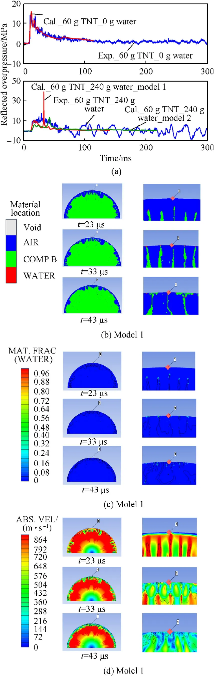
Fig.7.Experimental and numerical results for the cases of the water-to-explosive weight ratios of 0 and 4 at the scaled distance of 0.668 m/kg1/3.(a)Comparison of the pressure histories at the monitoring point;(b)Material location distribution at three points in time before impacting,during impacting,and after impacting of water;(c)Volume fraction of water at same three points of time;(d)Velocity magnitude distribution at same three points in time.
The water explosion process with water placement is analysed based on both experimental results and the validated numerical simulation results as follows:
(1)In the initial stage of the explosion immersed in water layer,the detonation wave propagates into the water to form a shock wave in the water,while rarefaction waves are propagated back into the detonation products.When the shock wave reaches the interface between water and air,it reflects back into the water and forms rarefaction waves.“Spallation”phenomena will occur near the free surface.The water due to spallation will be broken into droplets and double accelerated,leading to the injection and splashing into the air.In the simulations,these phenomena are indicated by the velocity fluctuations observed in the water velocity profiles of Fig.10 at the initial stage of the explosion.The integrity of the water layer around the explosive may be destroyed according to the ratio of the water-to-explosive weight or the thickness of the water layer during the spallation process.For the case of a small water-to-explosive weight ratio such as 5 in Fig.10,the integrity of the water layer around the explosive can be maintained up to a scaled distance of approximately 0.25 m/kg1/3,while for the larger water-to-explosive weight ratio of 20,the integrity of the left water shell after spallation will be maintained up to a scaled distance of approximately 0.55 m/kg1/3.This value is close to the scaled distance of 0.668 m/kg1/3.As listed in Table 5,for the cases at a scaled distance of 0.668 m/kg1/3,the peak value of the reflected overpressure measured with water placement is still greater than that of the case without water.These results reveal that at a small scaled distance of less than 0.55 m/kg1/3,particularly for the case of 0.25 m/kg1/3,the integrity of the water shell will not be fully destroyed.The energy of the explosion is transferred to the bulk water by the pressure acceleration during expansion,and the water shell will be driven to a relatively high speed with a relatively high impulse.The impact of high-speed moving“shell”water on the wall increases the destructive power of the explosion.Therefore,the peak value of the reflected overpressure measured with water not only is much greater than that of the explosion without water but also increases with the increase in the water-to-explosive weight ratio.
(2)With the increase of the scaled distance,due to the Tayler and Helmholtz instabilities,the high-speed moving water shell is further split,broken and atomized.Water droplets of different sizes and shapes affected by different inertia and air/gas resistance begin to disperse in air/gas,gradually slowing down,while the air shock wave is propagating away.At scaled distances such as 0.668 m/kg1/3,the air shock wave first reaches the wall surface and produces a reflection overpressure with a peak value of approximately 10 MPa.However,the dispersion of the water droplets is relatively low at such a distance so that the volume fraction and the velocity of the water droplets front are relatively high according to Fig.10,resulting in a relatively high impulse of the water phase.Then,due to the successive impact of the dense water droplets on the pressure sensor surface,the reflected overpressure curve shows fluctuation with a high amplitude for a certain time period.
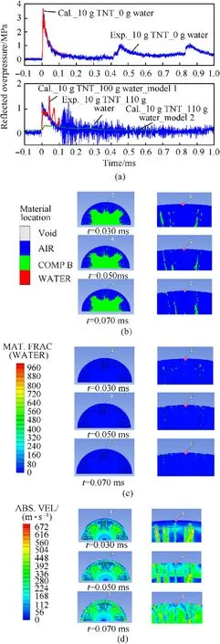
Fig.8.Experimental and numerical results for the cases of the water-to-explosive weight ratios of 0 and 11 at the scaled distance of 1.21 m/kg1/3.(a)Comparison of the pressure histories at the monitoring point;(b)Material location distribution at three points in time before impacting,during impacting,and after impacting of water;(c)Volume fraction of water at the same three points in time;(d)Velocity magnitude distribution at the same three points in time.
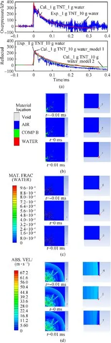
Fig.9.Experimental and numerical results for the cases of the water-to-explosive weight ratios of 0 and 10 at the scaled distance of 2.5 m/kg1/3.(a)Comparison of the pressure histories at the monitoring point;(b)Material location distribution at three points in time before impacting,during impacting,and after impacting of water;(c)Volume fraction of water at the same three points in time;(d)Velocity magnitude distribution at the same three points in time.

Table 5Measured reflected overpressures at different scaled distances.
(3)With a further increase in the scaled distance,the water droplets further split,break up,atomize,decelerate and even evaporate in the air.The energy consumption processes of the water movement,dispersion and even phase change begin to decrease the velocity of water phase.The volume fractions of the water droplets front are generally less than 0.1 and the velocities are decelerated below 80%of their peak values when the scaled distance is greater than 0.8 m/kg1/3according to Fig.10,which means that the impulse of the water droplets phase front will be greatly reduced.Therefore,it is observed that when the scaled distance is 1.21 m/kg1/3,the reflective overpressure peaks for the water-to-explosive weight ratios of 4 and 11 are reduced by nearly 60%compared with the cases without water,and so that a remarkable effect of the water-to-explosive weight ratio on the blast mitigation degree is observed.At the scaled distance of 2.50 m/kg1/3,the peak value of the reflected overpressure at the water-to-explosive weight ratio of 10 is 30%lower than that without water,still showing a significant mitigation effect.However,the degree of mitigation degree appears to be lower than that at the scaled distance of 1.21 m/kg1/3.This outcome occurred because for this case,the absolute magnitude of the overpressure decreased much less than that in the previous case.
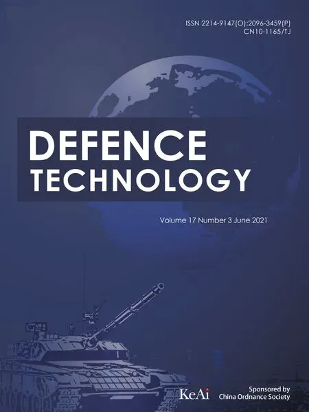
Fig.11(a)shows the relationship of the peak reflected overpressure at different scaled distances and water-to-explosive weight ratios.At a small scaled distance,the amplitude of the reflection overpressure increases greatly with the water-toexplosive weight ratio,implying that the method of directly wrapping the explosive with water for the explosion may have more destructive effects on the reflection overpressure at small scaled distances(<0.25 m/kg1/3).The numerical simulation results confirm this conclusion as shown in Fig.11(b).
At a larger scaled distance,an appropriate amount of water can effectively decrease the amplitude of the reflected overpressure.Both the rise and fall of the reflected overpressures are closely related to the scaled distance and the water-to-explosive weight ratio.It is clear that the scaled distance of 0.668 m/kg1/3is a critical value of the rise and fall for the experiments as shown in Fig.11(a).Considering the results presented in Fig.10,this critical value may correspond to the 0.07-0.4 vol fraction of the water phase front and the 0.7-0.8 non-dimensional velocity of the water phase.
In practice,when using water to mitigate the hazard of the explosive in confined space,it is necessary to design a reasonable water-to-explosive weight ratio based on the scaled distance.In the present investigation,in the water-to-explosive weight ratio range of 5-20,the critical scaled distance for space walls should be designed to be in the range of 0.7-0.8 m/kg1/3in order to obtain effective mitigation.
5.Conclusion
With the spherical explosive immersing in spherically constrained water in vessels,a series of explosion experiments were carried out with scaled distances in the 0.255-2.50 m/kg1/3range and the water-to-explosive weight ratios in the 0-20 range.Then,to elucidate the mechanism underlying the mitigation effects,numerical simulations were conducted for the typical experiments based on the AUTODYN software.Through the comparison of the reflected overpressure and the flow field,the mitigation effects of water on explosive shock were compared and analysed.The following conclusions were obtained:
1)In the scaled distance range of 0.255-2.5 m/kg1/3,the reflected
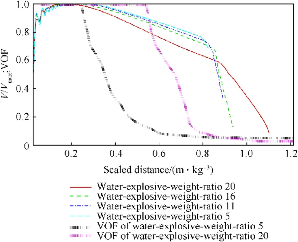
Fig.10.Non-dimensional profiles of the water velocity plotted versus scaled distance and the volume fraction of the water front during the explosion process with different water-to-explosive weight ratios.
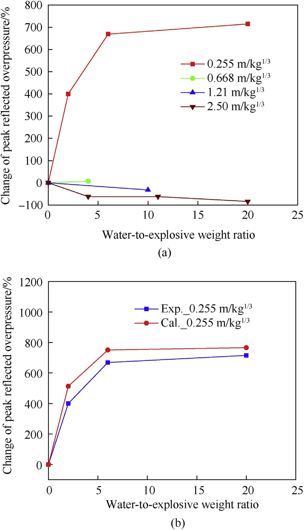
Fig.11.Influence of the water-to-explosive weight ratio on the reflected overpressure at different scaled distances.(a)Experimental results;(b)Comparison between numerical simulations with model 1 and experiments for the cases with the scaled distance of 0.255 m/kg1/3.
overpressure peak values on the inner wall of confined spaces(the volume of vessel is much greater than that of the explosive)are observed to change nonmonotonically;the overpressure peak values increase with the water-to-explosive weight ratio for the small scaled distances and decrease with the water-toexplosive weight ratio for large scaled distances.
2)When the scaled distance is equal to or less than 0.255 m/kg1/3,the reflected overpressure is significantly aggravated with the increase in the weight-to-explosive weight ratio.An eight-fold increase in the overpressure for the water case is observed compared to the case without water.This effect is due to the bulk accelerated water shell and dense water phase front impacting with a high impulse converted from the explosion.
3)At the scaled distance of 1.21 m/kg1/3,the water-to-explosive weight ratio below 20,the water layer significantly reduces the peak value of the reflected overpressure.A degree of mitigation of 60% can be attained,while at the scaled distance of 2.50 m/kg1/3and the water-to-explosive weight ratio of 10,30%mitigation is attained.This effect is due to the water phase impacting with lower impulse due to the energy dissipation of breakup,atomization and dispersion of the water phase.
4)In practice,when using water to mitigate the hazard of the explosive in confined space,it is necessary to design an appropriate critical scaled distance for a certain range of the water-toexplosive weight ratios.In the water-to-explosive weight ratio range of 5-20,the critical scaled distance for effective mitigation designed for space walls should be in the range of 0.7-0.8 m/kg1/3.
Declaration of competing interest
The authors declare that they have no known competing financial interests or personal relationships that could have appeared to influence the work reported in this paper.
Acknowledgements
This study was funded by National Natural Science Foundation of China,grant ID:11172245.
- Defence Technology的其它文章
- Defence Technology
- Pressure relief of underground ammunition storage under missile accidental ignition
- Fabrication and analysis of TIG welding-brazing butt joints of in-situ TiB2/7050 composite and TA2
- Effect of the end cap on the fragment velocity distribution of a cylindrical cased charge
- A novel DOA estimation algorithm using directional antennas in cylindrical conformal arrays
- Research on the intermediate phase of 40CrMnSiB steel shell under different heat treatments