Effect of the end cap on the fragment velocity distribution of a cylindrical cased charge
Wei Liao,Jian-wei Jiang,Jian-bing Men,Shu-you Wang,Mei Li,Han Liu
State Key Laboratory of Explosion Science and Technology,Beijing Institute of Technology,Beijing,100081,China
Keywords:Cylindrical cased explosive Fragments velocity End cap X-ray radiography Gurney formula
ABSTRACT The prediction of the fragment velocity distribution of a cylindrical cased charge with end caps is one of the key issues to assess the damage efficiency of the warhead.However,limited work has been conducted to predict the fragment velocity distributions along the axis of cylindrical cased charges with end caps.This paper presents a study of the velocity distribution of fragments caused by the explosion of a cylindrical cased charge with end caps.The fragment velocity distribution and the end cap velocity were determined by an X-ray radiography method,and the axial fragment distribution was determined by witness plates.It was found that the velocities of fragments,especially near the edge,were increased when the end caps were added,and the position of maximum velocity is closer to the non-detonation end.The fragment velocities were increased,and the fragment projection range was decreased with the increase of the thickness of the end cap.A formula for fragment velocity distributions of a cylindrical cased charge with end caps,which is based on Huang’s formula,was proposed by the theoretical analysis and data fitting and validated experimentally.The results indicate that the proposed formula is accurate in predicting the fragment velocity distribution along the axis of a cylindrical cased charge with end caps detonated at one end.
1.Introduction
1.1.General background
The impact of fragments is one of the most critical ways to destroy the target structure by the cased explosive charge.The cylindrical cased charge is widely used to generate high-velocity fragments.A commonly used structure of the cylindrical cased charge is a cylindrical casing filled with explosive,which is detonated at the centre of one end.The cylindrical casing will be accelerated by the highly pressurised products of the explosive charge after detonation,and then ruptures into a large number of fragments with different masses and velocities.The fragment velocity is an essential parameter for evaluating the damage efficiency of warhead,so it is necessary to establish the formula for calculating the parameter.
1.2.Studies on an infinitely long cylindrical cased charge
In early studies,the cylindrical warhead was simplified to an infinitely long cylindrical cased charge(see Fig.1a).Gurney[1]applied energy balance to establish a formula for calculating the initial velocity of an expanding cylindrical casing,which was widely used to predict the initial velocity of the natural fragment in the next few decades because of its accuracy.The formula can be expressed as:


Fig.1.Different models of cylindrical cased charge.
Unlike Gurney’s method,Baum and Stanyukovich[2]applied momentum balance and ignored the rapture of casing during the explosion to find another formula for calculating cylindrical casing’s initial velocity,as follows:

whereDis the detonation velocity of the explosive charge.According to Baum’s model,the velocity depends on the detonation velocity of explosive charge rather than the energy density of the explosive charge in Gurney’s method.
1.3.Studies on a finitely long cylindrical cased charge with open ends
In the past decades,the non-uniform fragment velocity caused by“edge effects”was found in the experiments[3],and the axial distribution of fragment velocities has been extensively studied[4-12].Gurney and Baum’s formula cannot describe this distribution because the real warhead is not an infinitely long cylinder,but a cylinder with open ends(as shown in Fig.1b).The explosive gas will leak from the open ends after the detonation,resulting in the low velocities near the warhead edges.Based on the Gurney formula,Zulkoski[4]proposed a correction formula based on the experimental results to describe the effect of rarefaction wave at the ends,as follows:

wherexis the distance from the detonation point along the cylinder axis(see Fig.1b),Lis the length of the cylinder,dis the diameter of charge andVGurneyis the velocity predicted by Gurney formula(Eq.(1)).Charron[6]proposed a correction formula for Gurney velocity according to“geometric equivalence”mentioned by Randers-Pehrson[5],where a reduced amount of explosive near the cylinder edges is considered to describe the energy loss caused by the axial rarefaction wave.According to his model,the expression for the velocity distribution is as follows:

whereF(x)is expressed as:

whereris the radius of the cylinder.However,the calculation results from Eq.(3)and Eq.(4)do not agree with the experimental data[10],and the distributions yield zero velocity at the detonation end.Hence,Huang[10]proposed another correction formula(as shown in Eq.(6))based on the experimental results and verified it by additional tests.Their proposed formula is given by:

1.4.Studies on a finitely long cylindrical cased charge with end caps
To increase the kinetic energy of the fragment,the initial velocity of fragments near the edges is increased by adding end caps to suppress the effect of rarefaction waves(see Fig.1c).The numerical and experimental studies[13]indicated that the end cap can effectively inhibit the generation of axial rarefaction waves at both ends,and the results of X-ray radiography tests[14]suggested that end caps increased the fragment velocity close to the detonation end by 27%and that close to the non-detonation end by 16%.However,the suppression mechanism of rarefaction waves by end caps has not been investigated,especially the effect of end cap thickness on the fragment velocity distribution.The thickness of the end cap is one of the critical parameters in the design of the warhead.In addition to the effect of the end cap on the initial velocity,it is also unclear how the end cap affects the fracture characteristics of the casing and the projection angles of fragments.In the present work,the effect of the end cap on the initial velocity was studied by theory and experiment methods,and a new correction formula based on Huang’s formula(Eq.(6))was proposed,which is applicable to determining the fragment velocity distributions along the axis of warheads with end caps on both ends.
2.Experimental
Due to the influence of explosion glare and air resistance,highspeed photography and the velocity sensor methods are challenging to obtain accurate results,so X-ray photography tests were conducted to measure the fragment velocity.The profiles of the casing can be accurately recorded on the film by X-ray photography,which was widely used in the measurement of the fragment velocity[10,14-17].The cylindrical cased charge was placed on the same horizontal plane of X-ray tubes,and the axis of the casing was perpendicular to the ground(as shown in Fig.2).To record the range of fragment projection angles(projection range)and size of the impingement hole,two witness plates were designed including a thick plate and a thin plate.The thick plate that made of 8 mm armour steel and placed 0.4 m away from the specimen was used to record the projection range of the fragments.The thin plate made of 1 mm Q235 steel and put 1 m away from the specimen was used to record the size of the hole pierced by the high-velocity fragment,and the size of the hole can reflect the characteristics of the fragment size[23].

Fig.2.Photo of site layout and schematic of the test setup.
The specimen consists of four parts:the charge,the casing,the front end cap,and the rear end cap.The end caps are glued to the casing,and the structure of the specimen is shown in Fig.3.The AISI 1045 steel was adopted in the experiments as the material of metal casing and metal end caps.The explosive filled in the casing was Composition B(Comp.B)and was detonated at one end.There is a small hole in the centre of the front end cap,which is used to place the detonator.Three thickness end caps of 3 mm,6 mm,and 9 mm were tested in this experiment,which corresponds to three specimens of 1#,2#and 3#respectively.The C/M ratio of the specimen is about 0.4 and the Gurney velocity is 2720 m/s,and the other parameters of specimens are listed in Table 1.
The specimen was placed on a PVC tube for keeping the specimen and X-ray tubes level.There are two X-ray tubes on 450 kV model(Scandiflash AB,Uppsala,Sweden),which will emit X-rays att1andt2respectively after the detonation,and the profiles of the metal casing with lower transmittance will be recorded at two different times on the film so that the expansion distance of the casing can be measured to calculate the fragment velocity.
3.Results
3.1.Data analysis of X-ray photos
As shown in Fig.4,the complete profiles of the three specimens were recorded,including the profiles of the casing,front end cap,and rear end cap at two different times.Comparing the profiles of the three specimens at the same time(t=30.7μs),it can be found that the casing with thicker end caps has a straighter outline,and the edge displacement of the casing is significantly increased.The positions of the end caps in the profiles indicate that the displacement of the front end cap is considerably larger than that of the rear end cap.Note the positions of the end caps att=30.7μs in different photos,the specimen with thicker end caps has a smaller end cap displacement.
Before the detonation tests,a benchmark photo used to measure the magnification ratio was taken.Based on the benchmark photo,the axial and radial magnification ratios of the test are calculated.Because the position of the film was fixed before the fragments arrived,so the real size of the image at a specific time can be calculated with magnification ratios.If the accuracy of the results is not strictly required,the magnification ratio can also be intuitively estimated by the 105 mm PVC tube placed under the specimen(see the bottom of the photos in Fig.4).
The method of measuring the velocity of the fragment is as shown in Fig.5.The profiles A,B corresponding to the two different times were outlined in the X-ray photos,and then moved the position of profiles until the axis of symmetry a and b coincided,and the final image is the relative positions of the casing and the end cap at two different times.The displacement of the casing was measured after dividing the fragment profile into 15 equal intervals to generate 16 points,and the velocities of fragments at different axial positions were calculated usingVi=Δli/(t2-t1),whereΔliwas measured on the final images using a rectangular coordinate system.The velocities of the end caps were calculated by measuring the displacement of the apex of the end caps.For example,the velocity of the front end cap was calculated byVfe=Δlf/(t2-t1).For the spallation phenomenon at the apex of the rear end cap of specimen 2# and 3#(see Fig.4b and c),the displacement was measured by the apex of the main body of the end cap.
The measurement results and the calculation results from Eq.(6)are shown in Fig.6.The fragment velocity near the edge was increased when the end caps are added,which is consistent with the results in Ref.[14].Comparing with the calculated results fromEq.(6),the fragment velocity close to the end of the casing with 3 mm end cap was increased by~14%(detonation end)and~12%(non-detonation end),and that of the casing with 6 mm end cap was increased by~23%(detonation end)and~16%(non-detonation end),and that of the casing with 9 mm end cap was increased by~27%(detonation end)and~18%(non-detonation end).

Table 1Parameters of experimental specimens.
Table 2 shows the velocities of the end cap.The velocity of the end cap decreases significantly as the end cap thickness increases,which is related to the increase in the mass of the end cap,and it is discussed in detail in Section 4.The velocity of the front end cap is much lower than the rear end cap,about 0.53 times the rear end cap,which is affected by the direction of explosive gas movement[18].Because the explosive gas moves along the axis to the rear end cap causes the rear end pressure to be higher than front cap.As a result,the rear end cap gets more kinetic energy.
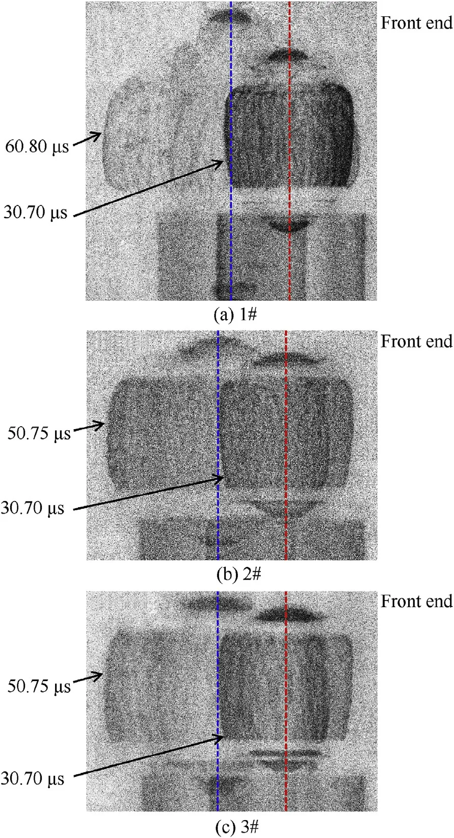
Fig.4.X-ray photos of specimens with different thicknesses of end caps.
3.2.Data analysis of witness plates
The thick plate placed 0.4 m away from the specimen blocked the fragments and prevented the film from being damaged,and the axial distribution of fragments can be recorded through the impact craters.The degree of casing fracture near the detonation end is much more severe than that near the non-detonation end(see Fig.7),and the fragments can be divided into“small fragments”(length-width ratio<3)and“strip fragments”(length-width ratio≥3)according to the shape and size of the impact craters.The fragments are scattered in the“fragment region”(within two red lines in Fig.7)and the strip fragments gather in the“strip fragment region”(within two blue lines in Fig.7).The“strip fragment region”is consistent with the phenomenon called“intense strip”in Ref.[24].Small fragments were formed in the large shear deformation,which exceeds the dynamic shear strength[10].Strip fragments are more massive than small fragments,with higher kinetic energy at the same velocity,but lower numbers.
The data measured from the thick plates is as shown in Table 3.It can be found that the width of the fragment area of the specimens 1#to 3# is gradually reduced(about 1 cm each),and the width of the strip fragment area is slightly reduced(<0.1 cm).The top distance and the bottom distance between regions are also reduced as the thickness of the end cap increases,especially the bottom distance changes significantly,and coincides at the bottom edge of the specimen 3#(see Fig.7c).The results show that the end cap has a suppressive effect on the axial projection of the fragments,and the width of the fragment region is smaller when the thicker end cap is used.
The characteristics of the fragment size were determined with the holes in the thin witness plate pierced by high-velocity fragments.The margin deformation of witness plates caused by the shock wave and the fixtures was removed manually for better placement.Then a photograph was taken with illumination from behind each plate.The images obtained in this way were converted into binary images(see Fig.8),and the hole area was detected by a simple threshold procedure due to the high contrast of the images.To investigate whether the thickness of the end cap affects the size of the hole,the average size of the impact hole was calculated(see Table 4).As shown by the results in Table 4,the average hole area of the specimen with 6 mm end caps relative to the specimen with 3 mm end caps is increased by 2.9 mm2(about 5.7%),and the average hole area of the specimen with 9 mm end caps relative to the specimen with 3 mm end caps is increased by 9.6 mm2(about 18.8%).These results are consistent with the hypothesis that the gradient of the radial pressure along the axis of the cylindrical casing near the edge causes high tensile stress and shear stress in this region[19-22].Because an increase in the thickness of the end cap reduces this gradient,the axial fracture of the casing are suppressed,but there are still“small fragments”in the fragment region,indicating that this gradient still exists and the casing is still effected by rarefaction waves.
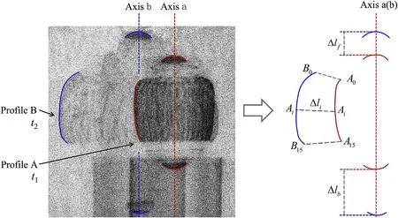
Fig.5.Schematic of fragment velocity measurement.
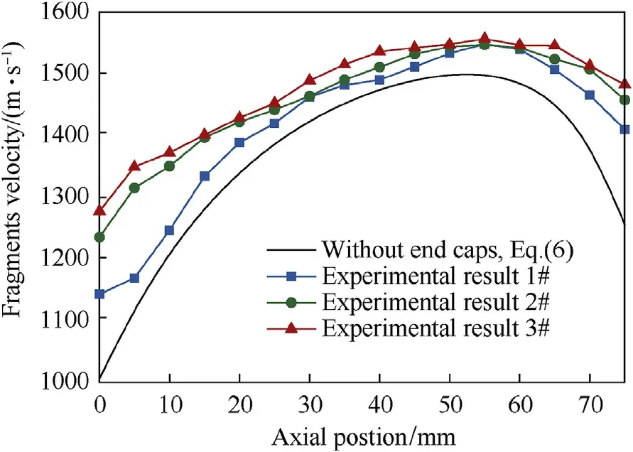
Fig.6.Fragment velocity distributions along the axis of specimens.
4.Calculation formula of fragment velocity
4.1.Establishing of the formula
Similar to Gurney’s model,the ideal explosion process of cased charge with end cap based on the hypotheses as follows:
(2)The velocities of the casing infinitesimals are uniform,and the velocities of the end cap infinitesimals are also uniform.
(3)The energy of the explosive is all converted into the kinetic energy of the explosive gasEg,the kinetic energy of the casingEcand the kinetic energy of the end capEe.
Under the uniform pressure of the explosive gas(see Fig.9a),the momentum balance equation of each infinitesimal of end cap or casing is as follows:

whereρis the density of casing or end cap,δis the thickness of casing or end cap,Sis the contact area between gas and metal.The integral of this formula can be obtained as follows:

Thus,the velocity of the casing and the end cap can be expressed as:

The two equations above are divided to obtain the ratio of the casing velocity and the end cap velocityk,as shown below:

The kinetic energy of end cap and casing can be expressed as:
There were sweet peas in it, and two rose trees, which grow beautifully, and in summer the two children were allowed to take their little chairs and sit out under the roses

Assuming that the velocity of the geometric centre of the explosive gas is zero,the axial velocity increases linearly from 0 toVe(see Fig.9b),and the radial velocity increases from 0 to Vc(see Fig.9c).The equivalent masses of the explosive gas in bothdirections,C/2 andC/3,can be obtained by integration,so the kinetic energy of explosive gas can be expressed as:

Table 2End cap velocities with different thicknesses.
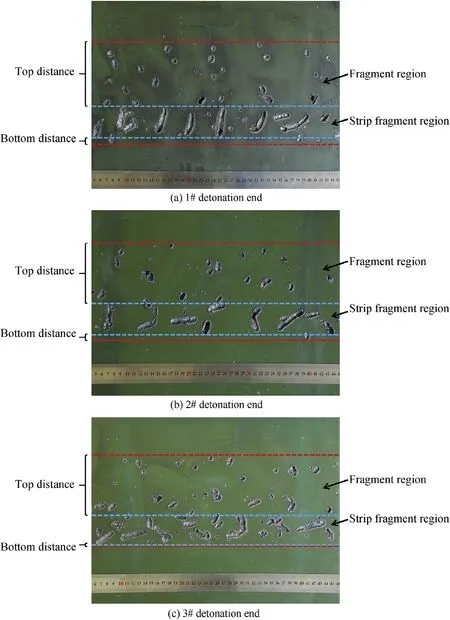
Fig.7.Fragment distributions on the thick witness plates.

Table 3Size of fragment regions on witness plates.

According to Hypothesis 3 and the law of conservation of energy,the total energy of the explosive charge can be expressed as:


Fig.8.Binary images of the fragment distributions on the thin witness plates.

Table 4Average area of holes on witness plates.
whereCis the mass of explosive charge,Eis the energy density of explosive charge.Equations(10)-(13)are solved simultaneously to obtain the casing velocity as follows:
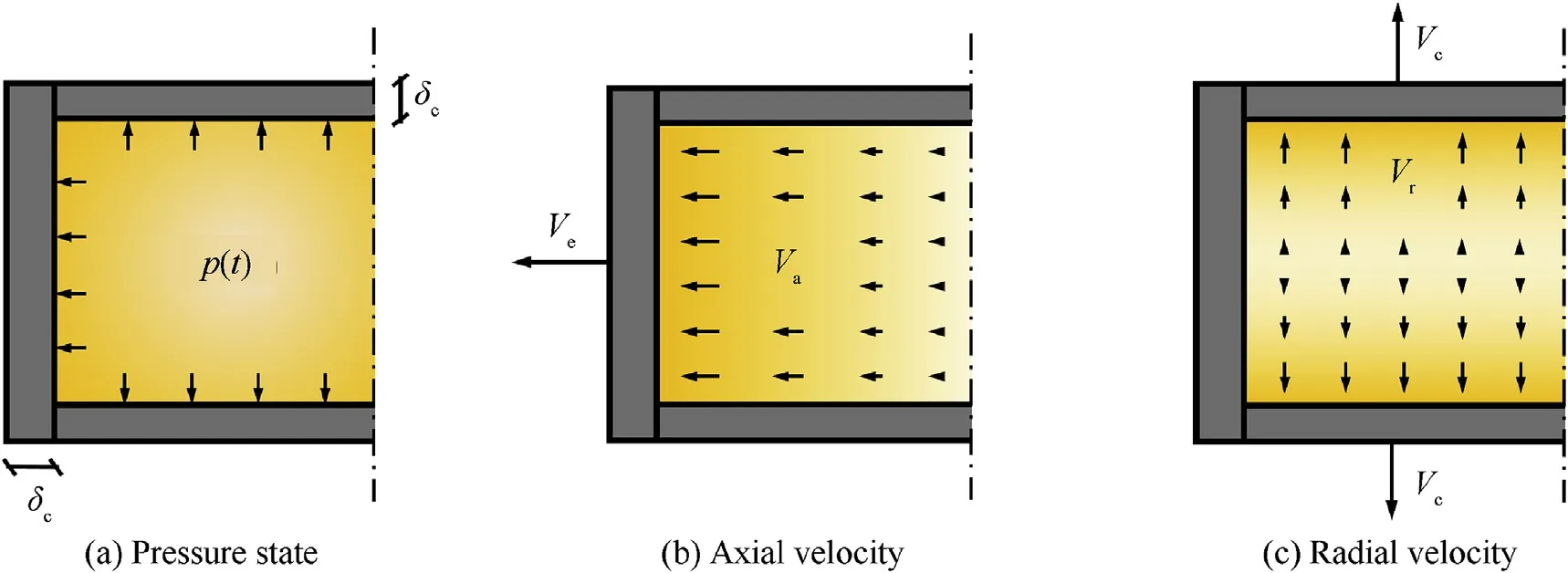
Fig.9.Schematic of the ideal explosion process of the warhead with end cap.
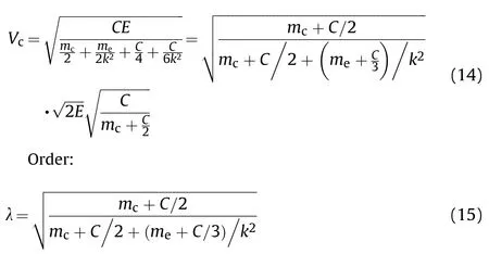
Eqs.(1)and(15)are substituted into Eq.(14),and the velocities of the casing and the end cap can be expressed as:

The velocities calculated from Eq.(16)are uniform,which is inconsistent with the results shown in Fig.6,indicating that this model cannot describe the velocity distribution of the fragments.To accurately calculate the fragment velocity distribution,a new empirical formula needs to be established.It can be concluded from the model that when the density of the end cap and the casing are equal,the fragment velocity depends on the ratio of the thicknesses δe/δc(see Eq.(10)and Eq.(15)).Besides,it can be seen from Fig.6 that the fragment velocities near the end are lower than those near the middle(“edge effect”),which indicate that the fragment ve- locity distribution is still affected by the rarefaction waves,so the fitting method proposed by Huang[10]is adopted:

whereF1is the correction term at the detonation end,F2is the correction term at the non-detonation end,andA,B,CandDare the coefficients determined by experimental data.The fragment velocity distribution of cased charge with end cap can be obtained as follows:

Firstly,the coefficientsA,B,C,andDare fitted by the leastsquares method based on the experimental results,and the fitting results are shown in Table 5.There are negative correlations betweenA,Candδe/δc,and the values ofBandDdo not change much whenδe/δc≠0.Then fitAandCwith an inverse proportional model,and calculate the average value ofCandDas the coefficient value when the warhead has end caps.
The calculation formulas of coefficients obtained by fitting are as follows:

Table 5Coefficients of the fitting formulas.
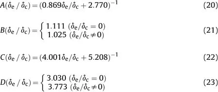
The correction coefficientsA,B,C,andDare substituted into Eq.(19)and the unified formula is obtained as:

whereBis 1.111(whenδe/δc=0)or 1.025(whenδe/δc≠0),Dis 3.030(whenδe/δc=0)or 3.773(whenδe/δc≠0).From the calculation formula of coefficients,it can be found that whenδe=0,the formula Eq.(24)is actually equivalent to Huang’s formula(Eq.(6)),and evolves to the Gurney formula whenδe→∞.Eq.(24)is an extension formula of the Huang’s formula,which can be used to calculate the fragment velocity distribution of a cased charge with end caps or open ends.

Fig.10.Comparison of the experimental and calculated results.
The accuracy of Eq.(24)was evaluated with the experimental data of specimens 1# to 3#(see Fig.10).Fig.11 shows the relative error between calculated results and experimental data.The average relative error was determined to be 1.06% with the maximum value of 4.56%for specimen 1#,0.67%with a maximum value of 1.87%for specimen 2#,and 0.77%with a maximum value of 1.22%for specimen 3#.The relative error near the detonation end is obvious because of the measurement error caused by large deformation of the casing in this area(see Fig.4).These results indicate that the proposed formula is accurate for predicting the fragment velocity distribution of cylindrical cased charge with end caps under the proposed experimental conditions.
4.2.Validation
To further demonstrate the accuracy of the proposed formula,test data of a cylindrical cased charge with end caps in Refs.[14]was chosen,as shown in Fig.12.Different size of cased charge with end caps(L=77mm,d=24 mm,D=30 mm)was tested in Ref.[14]with the same experimental method as section 2 was adopted.The AISI 1045 steel was adopted as the material of metal casing and end caps,and the Comp.B was adopted as the material of the charge.The calculation results at the detonation end are slightly lower than the test results in Ref.[14].Because Eq.(24)base on the results of the specimen with a centre hole on the front end cap and the explosive gas leaks from the hole after detonation(see Fig.3).This effect depends on the type and size of the detonator adopted in the experiment.The average relative error was determined to be 2.36%with a maximum value of 7.64%(see Fig.13).To further validate Eq.(24)with differentL/dandC/Mratios,the experimental results(Ref.[26])and simulation results(Ref.[27])of the specimen(L/d=2,C/M=0.889)were compared with the calculated results(see Fig.14).It evidenced that Eq.(24)has a good agreement with fragment velocity distribution of the different size specimen.Therefore the new formula can predict the fragment velocity well for most simple conditions of cased charge with end caps.
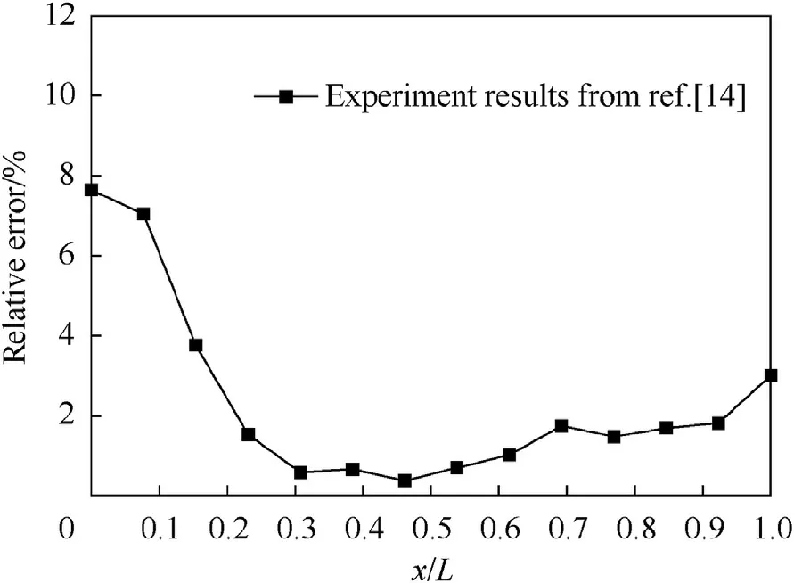
Fig.13.Relative errors between Eq.(24)and experimental results.

Fig.14.Comparison of Eq.(24)with experimental and simulation results[25].
5.Discussion
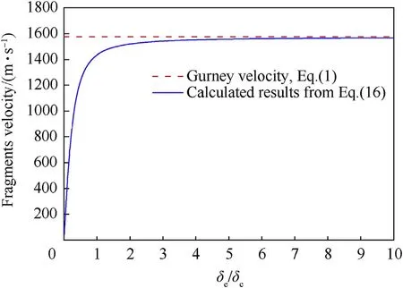
Fig.15.Fragment velocity for variousδe/δc ratios.
Eq.(16)are compared with Eq.(1)in Fig.15 and the structural parameters listed in Table 1 are adopted in these Equations.As shown in Fig.15,the fragment velocities calculated by Eq.(16)gradually approach the results predicted by Eq.(1)as the value of δe/δcincreases,consistent with the experimental results in section 2 that end caps increased the fragment velocity of the cylindrical cased charge.The theoretical analysis results indicate that the thickness of the end cap has a positive effect on the fragment velocity.However,Eq.(16)yield zero velocity atδe/δc=0,which is inconsistent with the test data in Refs.[10].Therefore,Eq.(16)is not applicable when the value ofδe/δcis close to zero,because the model ignores the velocity limit of the explosive gas,and thereby the energy of the explosive is all converted into the kinetic energy of the end caps.
The fragment velocity distributions of specimens(L/d=3,d=25 mm,D=31 mm)with differentδe/δcratios calculated by Eq.(24)are shown in Fig.16.The calculated fragment velocities of the specimens with highδe/δcratios with Eq.(24)are higher than that with lowδe/δcratios,especially the velocities near the end,consistent with the conclusion in Refs.[14]that the axial rarefaction waves generated from both ends of the casing with two end caps were suppressed.The locations of maximum fragment velocity of specimens with end caps(δe/δc≠0)are closer to the nondetonation end than that of the specimen without end caps(δe/δc=0),and the maximum fragment velocities with highL/dratios become close to the Gurney velocity(Eq.(1)).
The fragment velocity distributions of specimens(δe/δc=1,d=25 mm,D=31 mm)with differentL/dratios calculated by Eq.(24)are shown in Fig.17.The calculated fragment velocities of the specimens with lowL/dratios with Eq.(24)are lower than those predicted by Eq.(1).The maximum fragment velocities of specimens with highL/dratios become close and equal to the velocity predicted by Eq.(1),and the fragment velocities at the edge of specimens with differentL/dratios are almost equal except the fragment velocities at non-detonation edge of specimens with lowL/dratios,consistent with the conclusion for the cylindrical cased charges[11].
6.Conclusions
In the present work,a study of the velocity distribution of fragments caused by the explosion of a cased charge with end caps was investigated experimentally and theoretically.The fragment velocity distribution and the end cap velocity were determined by an X-ray radiography method,and the axial fragment distribution was determined by witness plates.An ideal model was built to analyse the critical influence factor of the fragment velocity distribution,and a modified formula for calculating the fragment velocity distribution of a cased charge with end caps was proposed and validated.The following conclusions can be drawn from the current study:

Fig.16.Fragment velocity distributions of specimens(L/d=3,d=25 mm,D=31 mm)with differentδe/δc ratios.
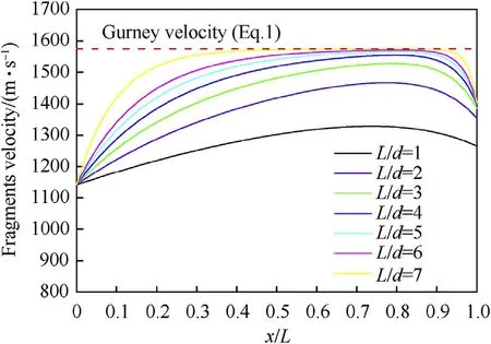
Fig.17.Fragment velocity distributions of specimens(δe/δc=1,d=25 mm,D=31 mm)with different L/d ratios.
(1)The end cap velocity is inversely related to the thickness of the end cap,and the velocity of the front end cap is always about 0.53 times that of the rear end cap for the analysed range of thickness ratio.The slight spallation is found in the X-ray photos when the thickness of the end cap is 6 mm,and the apparent spallation occurs when the thickness of the end cap is 9 mm.
(2)The fragment velocity distribution caused by the explosion of a cylindrical cased charge with end caps is also affected by the rarefaction wave near the edge.The ideal model shows the ratio between the thickness of the casing and the end cap is the critical influence factor of the fragment velocity distribution,and a modified formula for calculating the fragment velocity distribution of a cased charge with end caps was proposed.The experimental validation results indicate that the formula can accurately predict the fragment velocity distributions.
(3)The results from witness plates show that the width of the fragment region is reduced when the thickness of the end cap increases.This phenomenon may provide a new way to adjust the protection angle of fragments.
(4)The results from thin witness plates show that the average size of holes is increased when the thickness of the end cap increases,which indicates that the thicker end cap can better suppress the effect of rarefaction waves.
The fragment velocity distribution,projection range,and fragment size are all affected by the thickness of the end cap.The modified formula proposed in this paper can accurately predict the fragment velocity distribution of a cylindrical cased charge with end caps.However,the material of the end cap is required to be consistent with the casing in this formula,so the effects of end caps with different materials should be investigated as well.Additionally,to further investigate the effect of end caps on the mass distribution of fragments,our future work will be focused on the recovery experiment of fragments.
Declaration of competing interest
We declare that we have no financial and personal relationships with other people or organizations that can inappropriately influence our work,there is no professional or other personal interest of any nature or kind in any product,service and/or company that could be construed as influencing the position presented in,or the review of,the manuscript entitled“Effect of the end cap on the fragment velocity distribution of a cylindrical cased charge.”
Acknowledgement
We would like to express our gratitude for financial support from the exploratory project of State Key Laboratory of Explosion Science and Technology,China(No.QNKT19-09).
- Defence Technology的其它文章
- Defence Technology
- Pressure relief of underground ammunition storage under missile accidental ignition
- Mitigation effects on the reflected overpressure of blast shock with water surrounding an explosive in a confined space
- Fabrication and analysis of TIG welding-brazing butt joints of in-situ TiB2/7050 composite and TA2
- A novel DOA estimation algorithm using directional antennas in cylindrical conformal arrays
- Research on the intermediate phase of 40CrMnSiB steel shell under different heat treatments

