Inertial parameter estimation and control of non-cooperative target with unilateral contact constraint
Shung LI, Yuchen SHE, Jun SUN
a College of Astronautics, Nanjing University of Aeronautics and Astronautics, Nanjing 210016, China
b Shanghai Aerospace Control Technology Institute, Shanghai 201109, China
c Shanghai Key Laboratory of Aerospace Intelligent Control Technology, Shanghai 201109, China
KEYWORDS Non-cooperative object;On-orbit servicing;Post-capture control;Parameter estimation;Unilateral contact constraint
Abstract In this paper, the relative sliding motion between the target and the manipulator’s endeffector is considered and characterized as a unilateral contact constraint. A new possible solution is presented to estimate the inertial parameters of a non-cooperative target while the relative sliding motion exists. First, the detailed analysis of the dynamical model is presented, and a parameterexplicit linear time-varying model is obtained.Then,an extended state observer is constructed based on the new model,which can effectively estimate the unknown inertial parameters of the target when relative sliding motion exists.As the modified reactionless controller requires the knowledge of inertial parameters, a hybrid post-capture control scheme is also established based on the switch law between different controllers.The correctness and efficiency of the proposed algorithm are validated by numerical simulation, which proves a potential framework for the non-cooperative target postcapture operation.
1. Introduction
The on-orbit servicing technology for un-cooperative objects is the key to various applications such as large-scale spacecraft assembly,1space debris removal,2and space maintenance.Such missions are highly complex and involve many advanced technologies including manipulator path planning and post-capture control of the combined spacecraft.3,4Since the target is noncooperative, its inertial parameters are usually un-known to the control system,which may lead to accidents including saturation or damage of the manipulator joint,high non-linearity of the model,5and collision between the target and the chaser.Therefore, parameter identification and control is the key to the success of non-cooperative target capturing missions.
A lot of works have been reported in the areas mentioned above. Manhester and Peck proposed a recursive inertia estimation algorithm based on the linear time-varying form of the Euler equation,6and the inertial parameters are arranged into a vector and are estimated by the Least Mean Squares Method (LMS). Similar inertial parameter estimation approaches were also proposed such as the single direction excitation-response algorithm.7Another possible solution for the inertia matrix estimation problem was presented by Bergmann8, where the moment of the inertia matrix was extracted by measuring the period of nutation and precession of the torque-free rotation. At the meantime, Bandyopadhyay and Chung developed an error quaternion based control strategy, which can effectively handle the large target with high coupling effect on the moment of inertia tensor.9She et al.proposed a virtual coordinate system to estimate the moment of inertia and the position of Center of Mass(COM)of the combined spacecraft simultaneously.10Nguyen-Huynh and Sharf introduced a Forgotten Factor Recursive Least Squares Method (FFRLSM) into the controller gain adaptation problem with un-known inertial parameters.11As can be seen from these works, all the existing parameter estimation algorithms are based on the same principle:The parameter to be estimated is usually set to be a coefficient of the mapping between the input torque and the output angular acceleration, so that it can be extracted by the methods such as the LMS or Kalman Filtering. To generate the input, the controllers such as the fuzzy PID control and force feedback control12are adopted since they can be directly implemented without knowing the target’s inertial parameters. However, it is not the case for other advanced controllers such as the inversed chain control13,14or the reaction null space control.15Based on the reactionless space principle, the reaction null space control has been proved to be able to stabilize the system with minimum disturbance on the attitude of the base.16Additionally,another approach has been proposed by blocking the manipulator joints after capturing the target so that the single body attitude takeover control was developed.17This strategy is also widely adopted for adaptive controller design of tethered space robot attached to un-cooperative objects.18,19During the previous works, the target is assumed to be rigidly attached to the endeffector within the static friction region,so that the target is usually modeled as an external disturbance or a flexible appendage.
According to the discussion, it can be seen that the postcapture parameter identification is a difficult and risky task,20especially when the relative sliding motion between the target and the end-effector is taken into consideration.Hu characterized the relative sliding motion as a Unilateral Contact Constraint (UCC) to the manipulator end-effector. A mathematical model based on the complementary function was proposed to describe the relative motion between the target and end-effector.21Meanwhile, various frictional models were proposed such as the Coulomb friction model,the bristle model22and its 2D extension.23The friction signal was then generated and integrated into the model as passive control input of frictional joints.24As mention above, the reactionless controller relies heavily on the dynamic inversion of the system. Therefore, the inertial parameters estimation algorithm considering the UCC must be properly developed to ensure the success of the control process.
In this paper,the extra Degree of Freedom(ex-DoF)model is adopted and analyzed in detail.Then,the observation strategy of unknown parameters is addressed.Finally,the new state observer is integrated into a hybrid post-capture control framework to estimate the inertial parameters of the target when there is relative sliding motion between the target and end-effector. It should be noticed that the new state observer proposed in this paper requires the initial guess of the target COM. According to the previous research, the rough estimation of the target COM is possible.25,26However, this kind of estimation is often carried out in contactless mode before capturing the target, which means that the estimation error is often quite high and cannot be directly adopted by the controller. Therefore, a more accurate estimation process after capturing the target is still necessary to ensure the success of the mission. The rest of the paper is organized as follows:Section 2 presents the mission background and the detailed analysis of the ex-DoF model. Section 3 addresses the extended state observer and the hybrid post capture control framework. The simulation results are shown in Section 4 before the conclusion drawn in Section 5.
2. Mission background and modified contact model based on Ex-DoF
2.1. Mission scenario and definition of coordinate systems
To properly study the mission scenario, the following coordinate systems are defined:
(1) The inertial coordinate system Oi-XiYiZidenotes the inertial coordinate system, where the general motion of the combined spacecraft is studied.
(2) The manipulator end-effector local coordinate system Oe- XeYeZeis established at the geometrical center of the end-effector. It is used to study the relative motion between the end-effector and the target.
(3) The target body fixed coordinate system Ob-XbYbZbis centered at the COM of the target, and the location of the grasping point is defined in this coordinate system.
This paper is focused on the post-capture control phase,so that the pre-capturing operation of the manipulator is not considered, as shown in Fig. 1. The active spacecraft consists of a base and a manipulator, while the target is considered as a single rigid body. Due to the complex contacting dynamics,the capturing status does not imply that the end-effector and the target are rigidly connected.23,24Therefore, three new Degrees of Freedom (DoF) are defined in order to describe the position of the target with respect to the end-effector,and this paper is the direct continuation of our previous work.27From Fig. 1, it can be seen that the relative motion of the target is constrained within the x-z plane of Oe-XeYeZe,the 2-D translational motion and 1-D rotational motion can be completely described by the three ex-DoF l,θ,f,while the position of the COM of the target is noted as c,which is described by three parameters h,f and La. In Fig. 1,the point a denotes the initial contacting point, point b denotes the intersection point between target’s edge and La.The angle φ is fixed to be 90°. The detailed definition of the three ex-DoF can be found in our previous publications and it won’t be addressed in detail here.27,28
2.2. Observability analysis of parameters

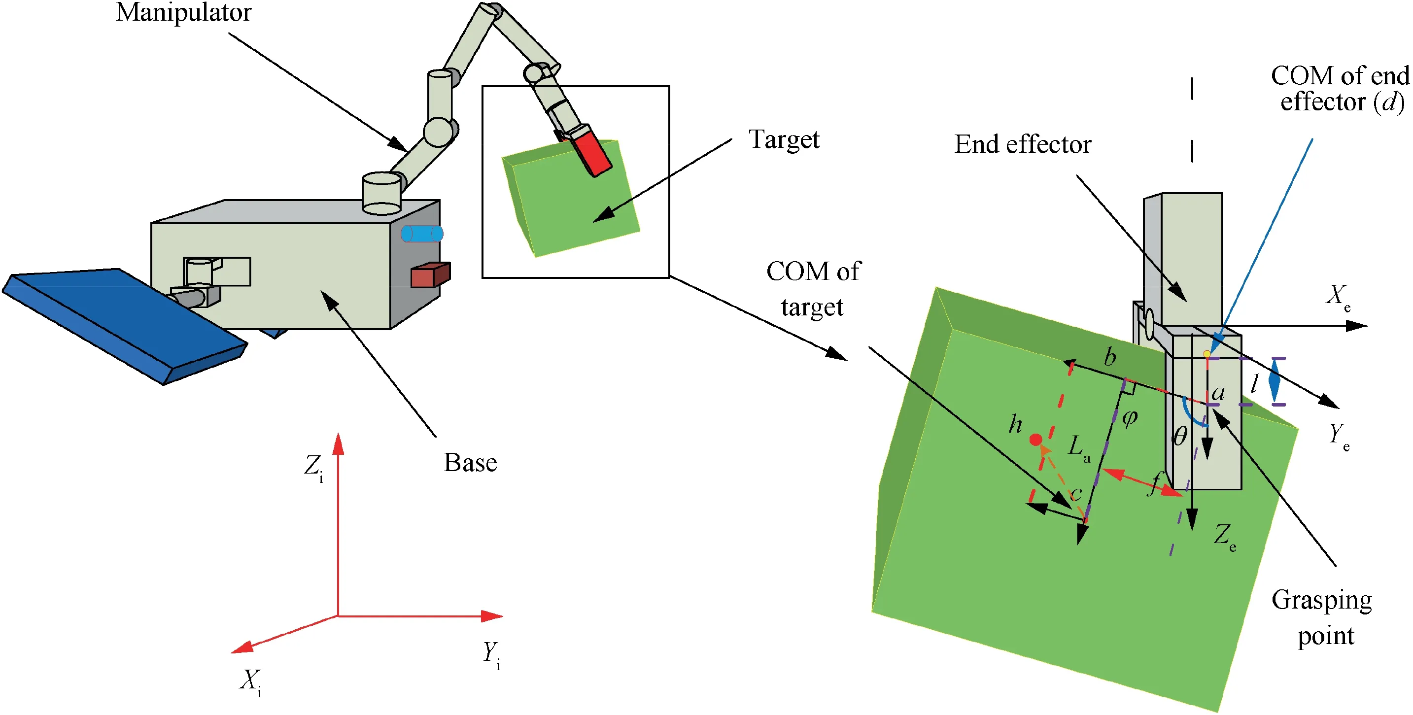
Fig. 1 Illustration of the mission scenario.
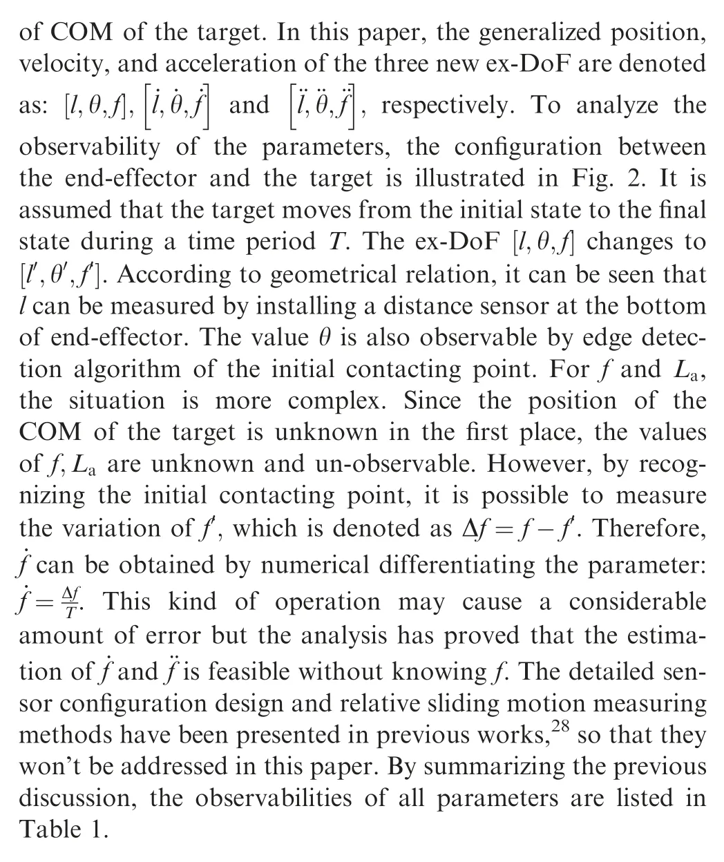
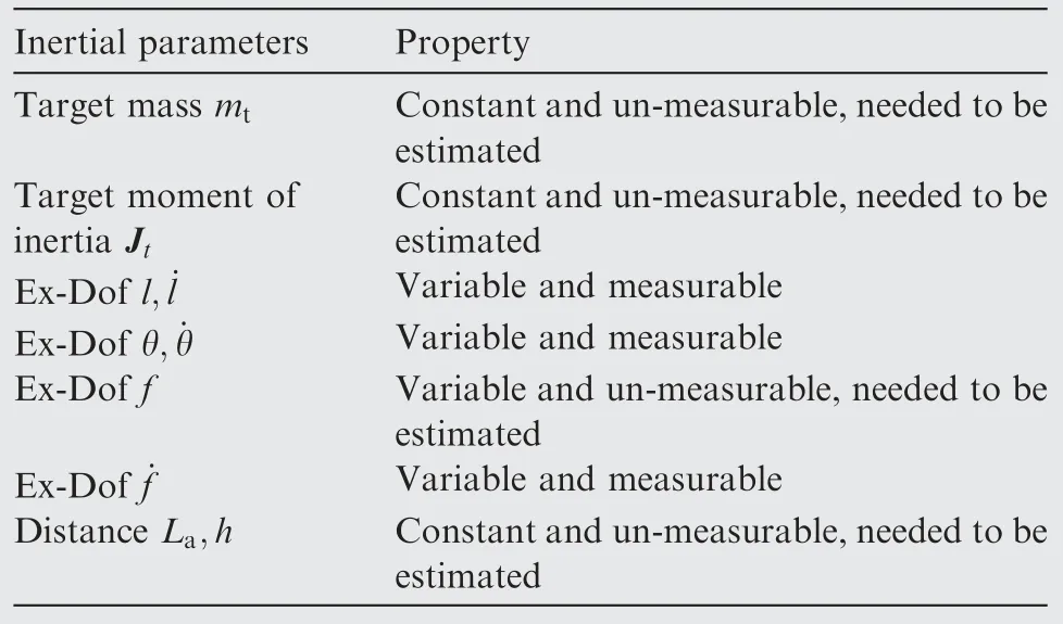
Table 1 Inertial parameters of the system.
As can be seen from Table 1 that the remaining unknown parameters are mt,Jt,f,La,and all rest parameters are measurable and can be used to design the state observer.
3. Dynamic analysis and extended state observer design
3.1. Dynamic model analysis with Ex-DoF approach

Fig. 2 Ex-DoF position and velocity analysis.
The dynamical model of the space manipulator with Ex-DoF can be derived based on the Newton-Euler principle.13By using the ex-DoFs defined in the previous section, the state vector can be reformulated as:

with P= [x ,y,z]Tdenotes the position of the base, θ denotes all the angle-related DoF of the active spacecraft, which includes the three dimensional attitude of the base and the joint angles of manipulator. l, f and θ are the ex-DoFs. Note that the vector θ and the scalar θ are two different parameters in the dynamic model. The compact dynamical model can be obtained as:
with Mt,Dt,Ctdenote the generalized mass matrix, the generalized damping matrix,and the matrix contains the non-linear terms,respectively.The vectors F can be given as F= [Fact,δ]Twith Fact, δ denote the control input and friction signals,respectively.The value of the friction force depends on the relative displacement and velocity between the target and endeffector, and it can be given by extended bristle model.23To obtain Eq. (2), the Lagrangian of the system is considered.For a free-floating manipulator,the potential energy V is often considered to be 0. After grasping the target, the total kinetic energy of the combined spacecraft can be expressed as the sum of the kinetic energy of the active spacecraft Eacand the target Et:

In Eq. (3), Jtand mtdenote the moment of inertia matrix and the mass of the target, respectively. Nacdenotes the number of joints of active spacecraft. The vector Pt,ωtdenote the inertial position and angular velocity of the target, Pidenote the inertial position of the ith joint, while ωjrepresents the angular velocity of the jth joint of the manipulator, respectively. Since the target is assumed to be completely noncooperative, the value of Jt, mtand Ptare all supposed to be unknown. From Eq. (1), it can be seen that:

where Θ represents the attitude angle vector of the manipulator base and φ denotes the joint angles of manipulator.To estimate these parameters, the detailed analysis of the dynamic model must be conducted. According to Fig. 1, the position of the target is given by:
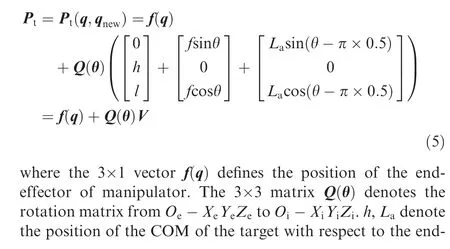

V is the relative position of target COM with respect to the end-effector. Arranging Eq. (6) yields:
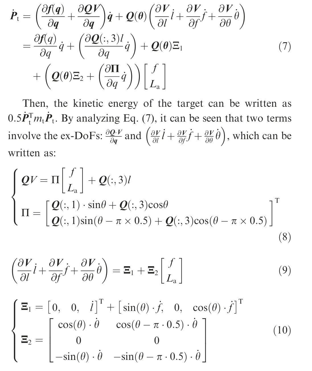
Note that the MATLAB citation rule is adopted in the discussion,wheredenotes the 1st column of the matrix Q.According to the previous discussion, the only unknown parameters in Eq.(7)are f and La.Other parameters,including l,θ,˙l,˙f and ˙θ are all measurable. It can be seen that Eq. (8) and(9) are explicit with respect to f and La, which is favorable for the estimator design.
3.1.1. Analysis of generalized mass matrix
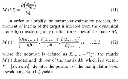
According to the Lagrange theory,the matrix Mtin Eq.(2)are given by:
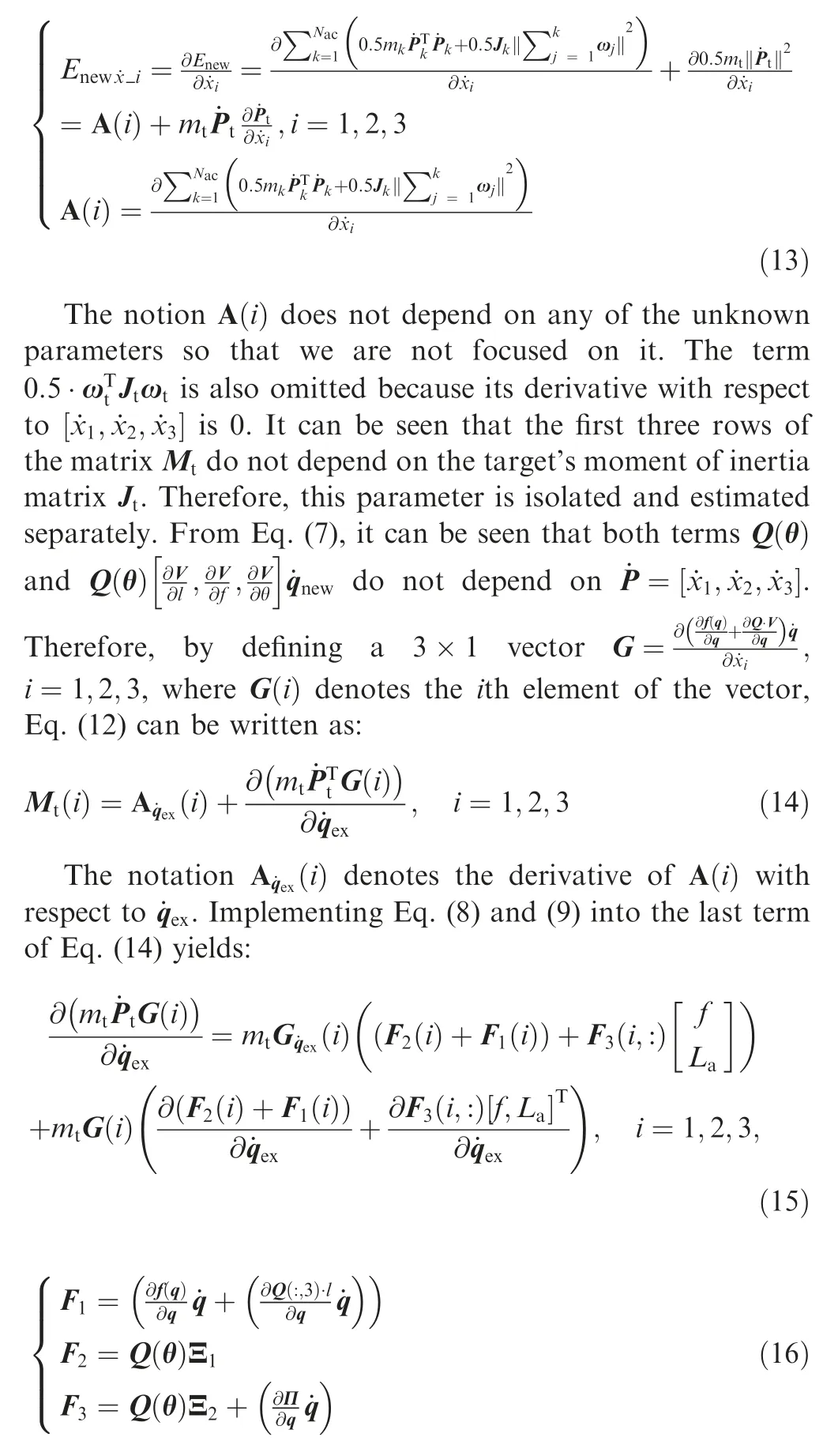
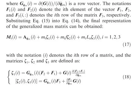
3.1.2.Analysis of the generalized damping matrix and non-linear matrix
The generalized damping matrix is also analyzed using the similar approach.Similar to Eq.(12),the matrix Dt,i=1,2,3is given by:
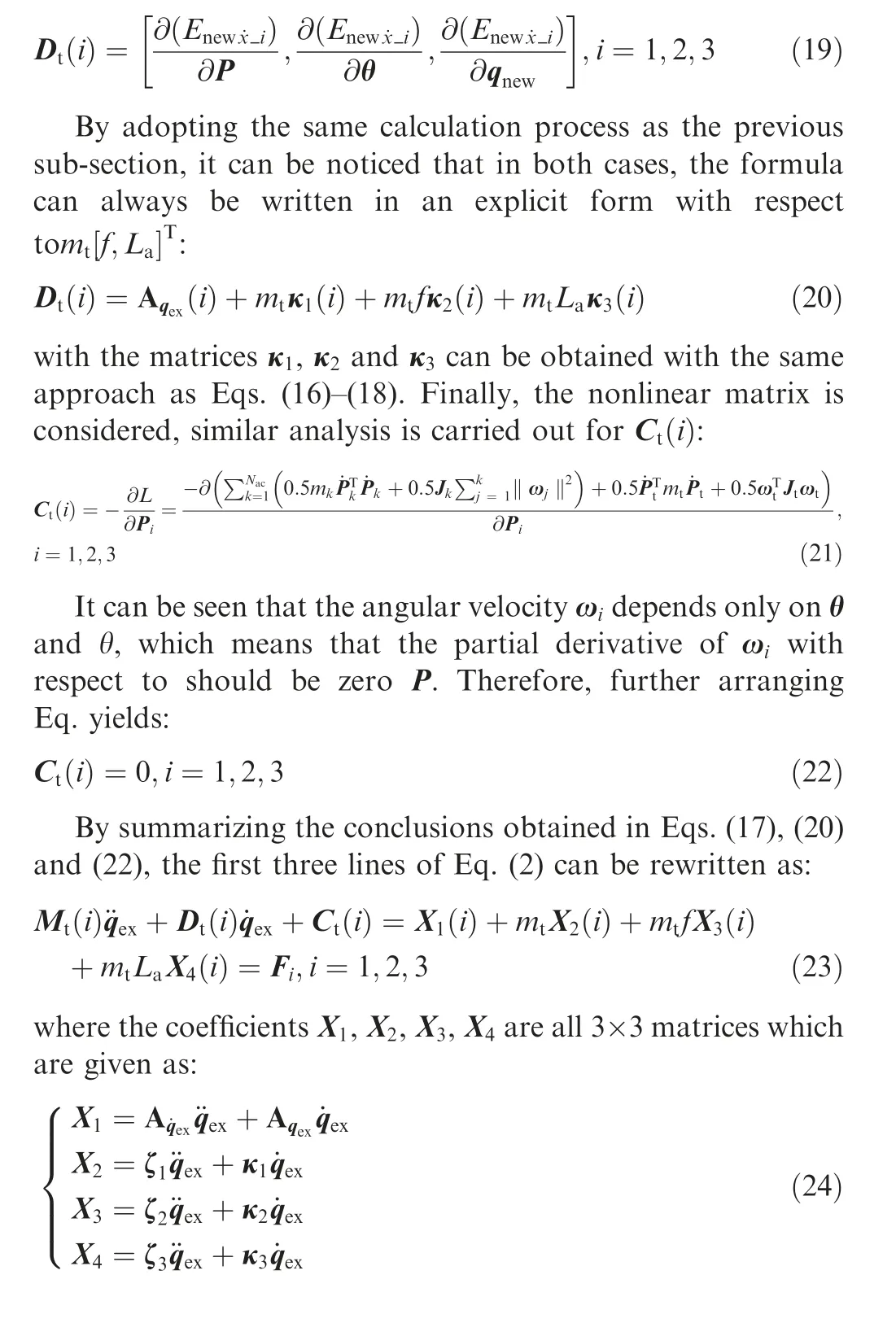
3.2. Design of the filtering algorithm
The section addresses the filtering algorithm dedicated to estimate the inertial parameters of the target. Firstly, a detail should be clarified. From Eq. (5) it can be seen that the position of the COM of the target can be divided into two parts:the 2D coordinate within the x-z plane of Oe-XeYeZeand the distancehto the x-z plane. The unknown constant parameter h has been omitted from the previous dynamical analysis.This is because the parameter h can be estimated with a pure kinematical approach. To show this, Eq. (6) is re-written in another form:
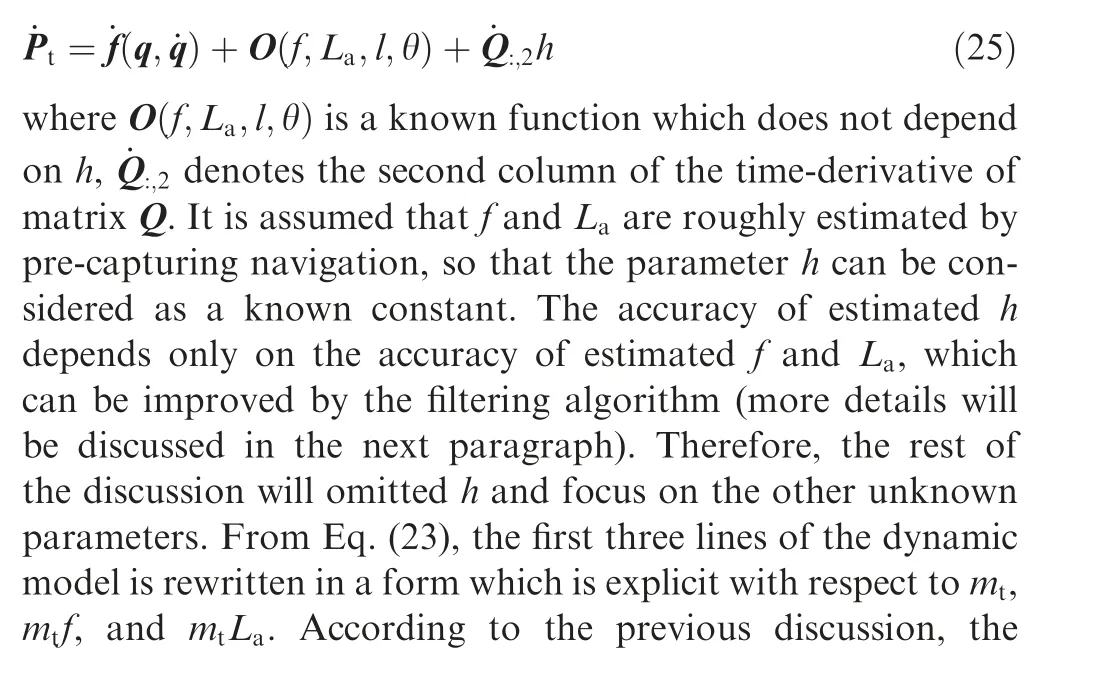
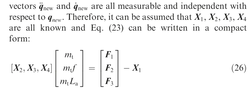
Eq.(26)is the standard formula for inertial parameter estimation.However,since the relative sliding motion between the target and end-effector has been considered, the unknown parameters are coupled, which is quite different comparing to the formula addressed in previous works.11,14Furthermore,it can also be seen that the unknown parameter f is time varying, so that the classic LMS is not applicable to estimate the unknown parameters. To solve this problem, a filtering algorithm is proposed in this paper,which requires an initial guess for the unknown parameters.The initial guess is generated for f and La, which are noted asand, respectively. Assuming the filtering algorithm starts at the time point t0, the discrete dynamic model is obtained by implementing the initial guess value into Eq. (26):
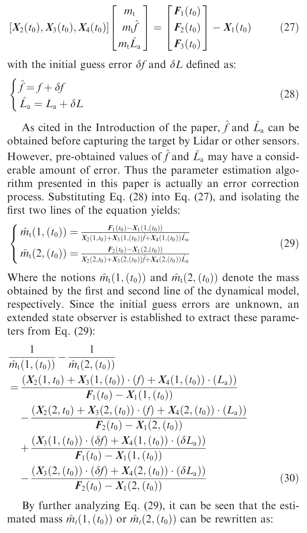
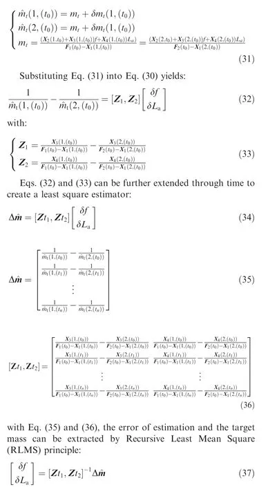
Once the initial guess error is properly extracted, the mass of the target can be measured by Eq. (29) by substituting the correct value ofandinto the formula.It should be noticed that in Eq. (29), two sub-equations returnand2,( , if the estimated valueandare exact, the two sub-equations will obtain the similar values with an acceptable error margin. It has been addressed that for the planar scenario case, the moment of inertia matrix would not appear in the first two lines of the dynamical model, and for the 3D scenario case, the moment of inertia matrix will not appear in the first three lines. In any case, it has been proved that adopting only the first two lines of the dynamical model is enough to estimate La, f and mt. Therefore, the estimation algorithm has the generality in both planar and 3D cases.
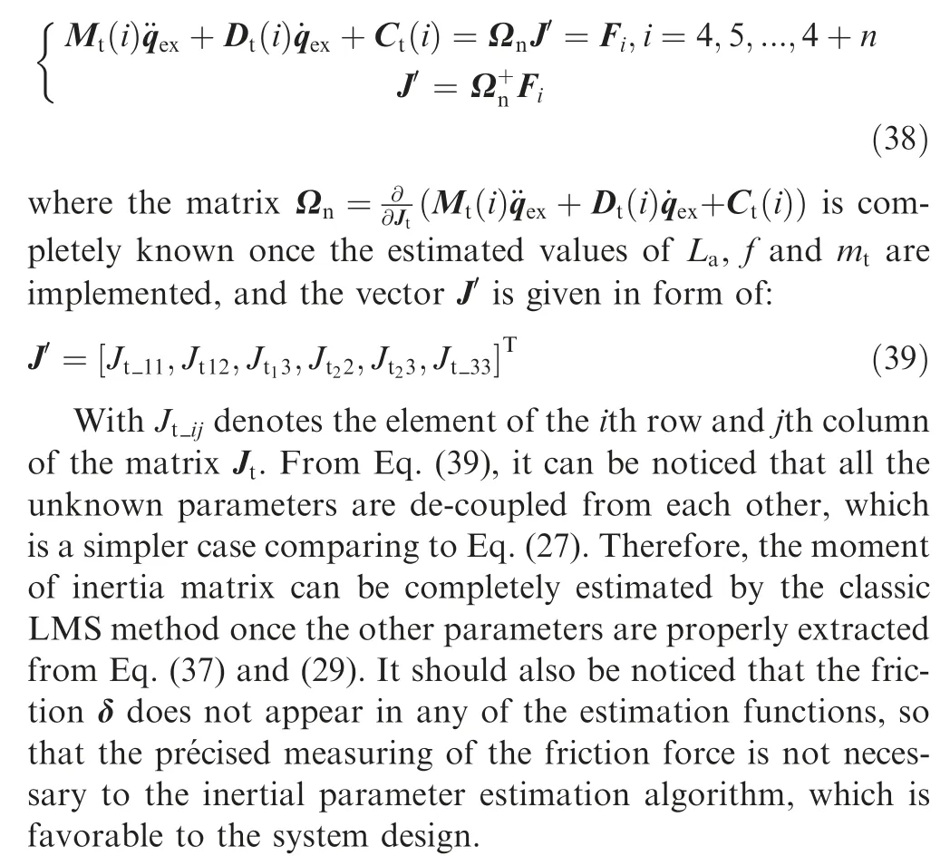
After obtaining La,f and mt,the only remaining parameter Jtcan be estimated adopting the 4th to (n+4) th lines of the dynamical model of the system and writing the formula in an explicit form with respect to the moment of inertia matrix of the target11,14:
3.3. Hybrid post-capture control framework
The object of the classic manipulator reactionless control is to de-tumble the target while minimizing the disturbance onto the base of manipulator.15,16In this paper, since the relative sliding motion between the manipulator and the target is considered, the reactionless controller is dedicated to reduce the relative sliding motion velocity in order to create the rigid connection between the end-effector and the target.To design such a controller, the dynamical model is reformulated in form of:
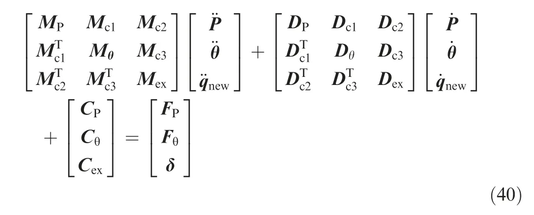
In Eq. (40), the matrices M,D,C with subscripts P,θ,ex denote the generalized mass,damping and non-linear matrices corresponds to the base,the manipulator and the target,while the matrices with subscriptsc1,c2,c3 denote the coupling matrices between the base, the manipulator and the target.The friction δ is not controllable. The vector θ is defined in Eq. (4) and it denotes the attitude of the base and the manipulator joints, which implies that Fθcorresponds to the control signal provided by the reaction wheels and the joint motors.The vector P denotes the position of the base, which means that FPcorresponds to the motion control thrusters onboard the satellite base. According to the reaction null space theory,FPshould remain 0 to ensure a conservation of momentum16.With this regard, the lower part of Eq. (40) is firstly isolated and analyzed separately:

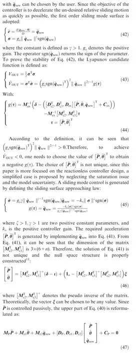
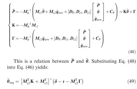
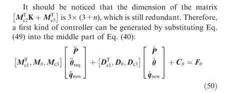
Furthermore, if the number of joint of manipulator n>3,the attitude of the base spacecraft can be further released by creating a second order reaction null space:

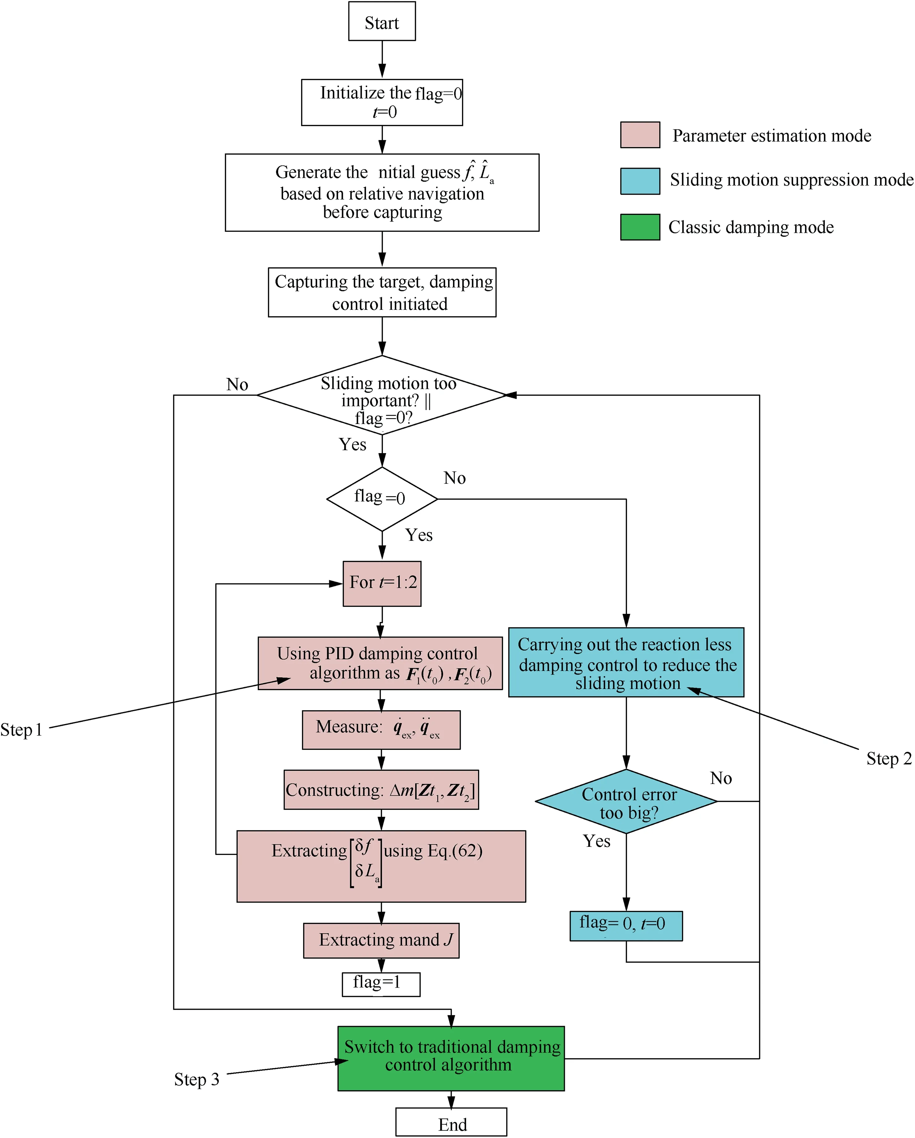
Fig. 3 Flow chart of the hybrid post-capture control process.
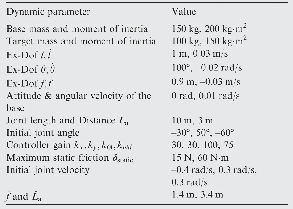
Table 2 Dynamic parameters of the planar simulation scenario.
With the desired angular acceleration of the base ¨Θdis generated similarly as Eq. (42):
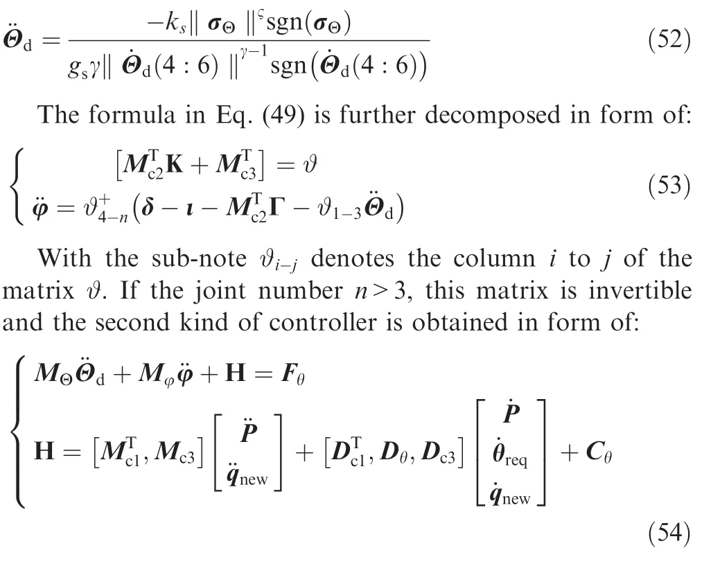
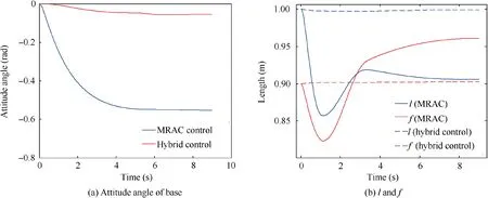
Fig. 4 Comparison of attitude of the base, ex-DoF l and f.
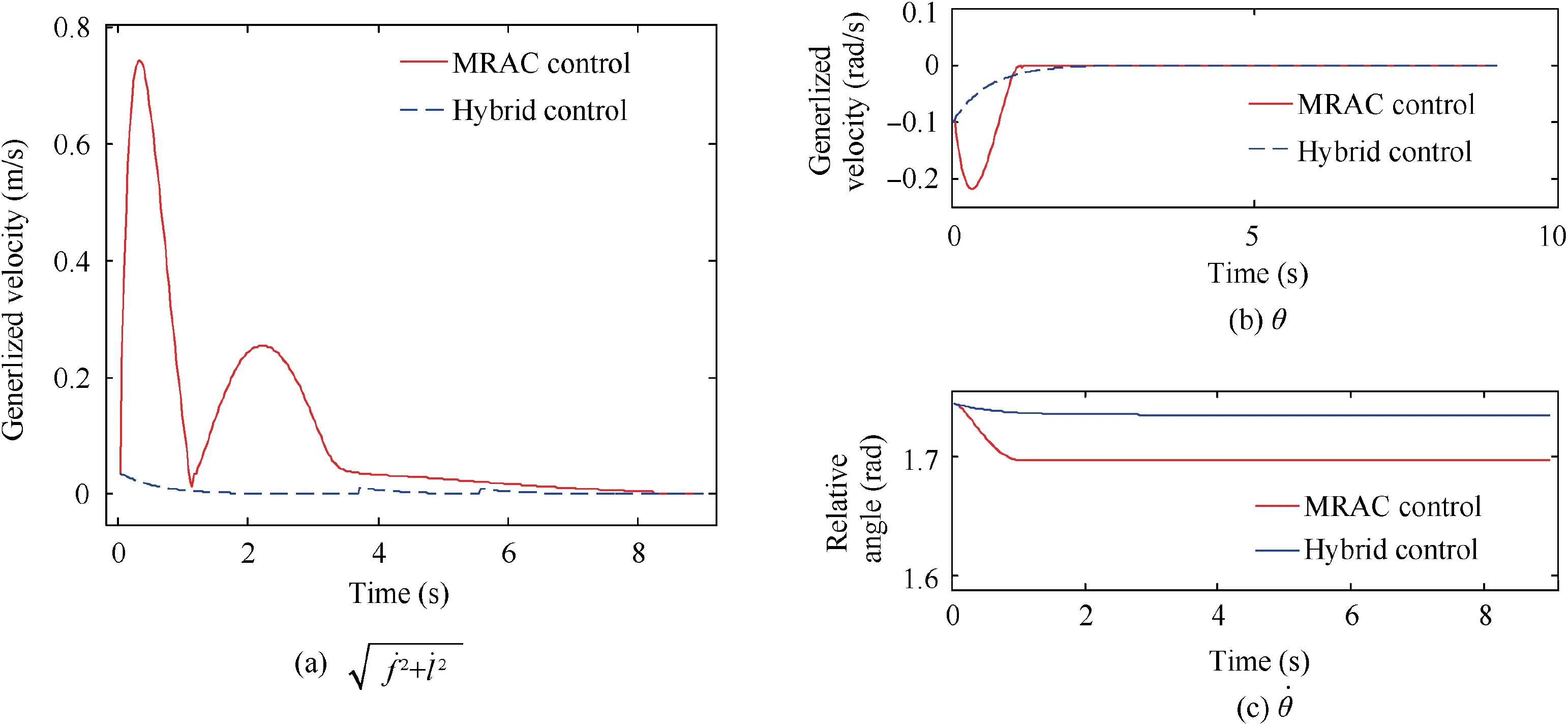
Fig. 5 Comparison of θ and θ˙.

Fig. 8 Variation of ex-DoF and manipulator joint (J1-J3) velocity.
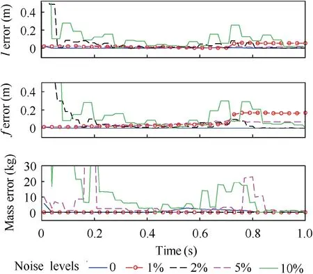
Fig.9 Comparison of estimation error with different noise levels on the system feedback signal.
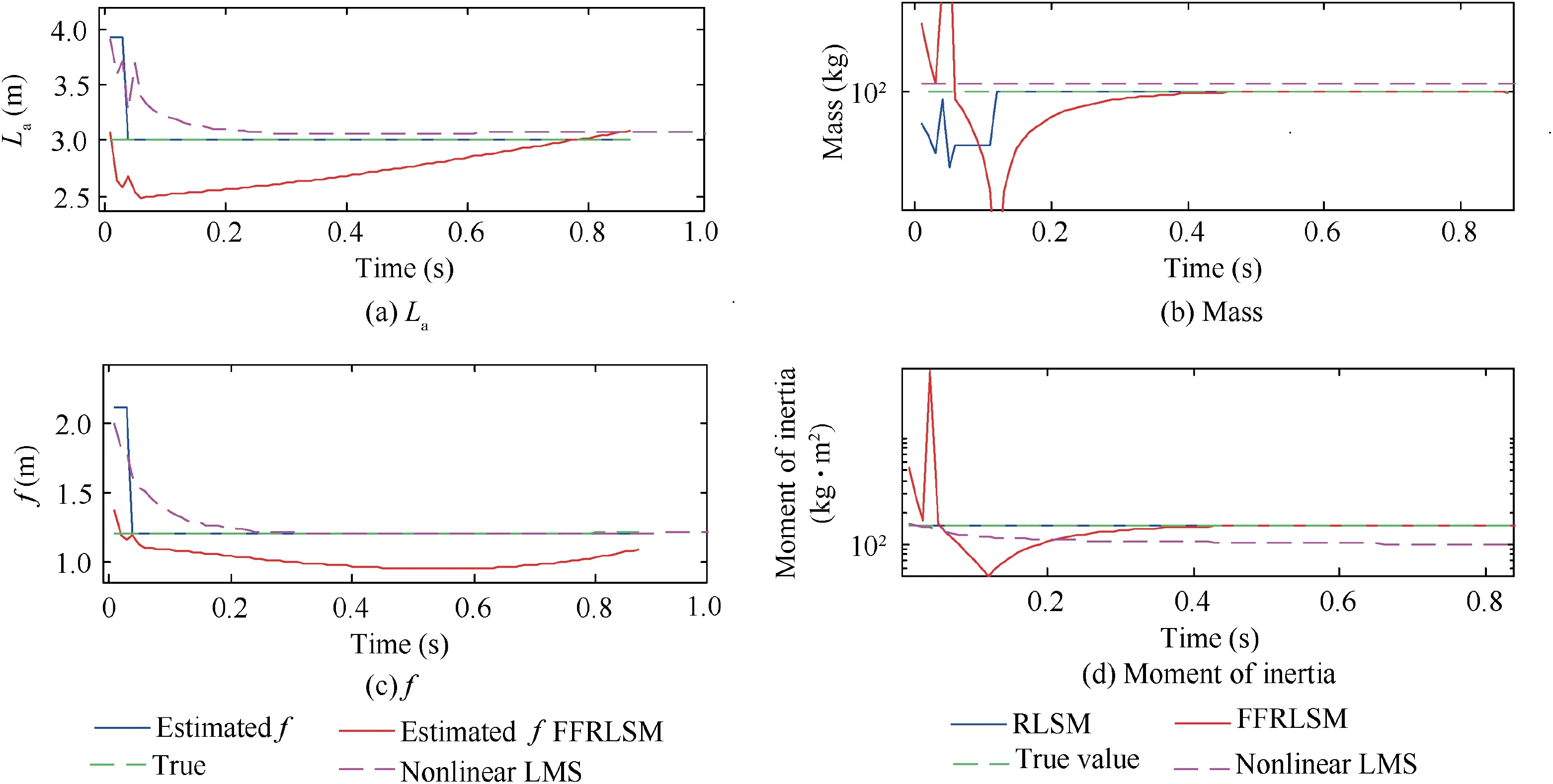
Fig. 10 Comparison of the proposed parameter estimation method with the FFRLSM.

Table 3 Dynamic parameters of the system.
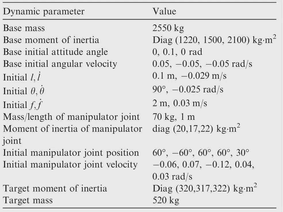
Table 4 Dynamic parameters of the system.
Therefore, the classic reaction null space control can be realized to reduce the relative sliding motion between the target and end-effector without causing any disturbance onto the attitude of the base.From Eqs.(50)and(54),it can be seen that the calculation of control input requires the knowledge of all inertial parameters of the system including mt,Jt,f, h and La. At the initial time point, these parameters are unknown to the control system. Therefore, a hybrid post-capturing control strategy should be established.The post-capture operation is performed by three steps:
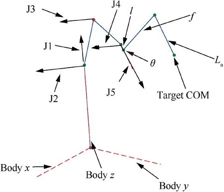
Fig. 11 Mission scenario of 3D test case.
Step 1.Parameter estimation mode:First,a traditional PID damping controller is activated and the unknown parameters of the target are extracted by the proposed algorithm.
Step 2. Sliding motion suppression mode: After obtaining the inertial parameters of the target, the modified reactionless control law is then called to cancel out the relative sliding motion between the end-effector and the target.
Step 3.Classic damping mode:Finally,once the target and the end-effector are rigidly connected, the classic reactionless controllers can be adopted to finish the rest of the stabilization process.15
The flow chart of the hybrid post-capture control framework is shown in Fig. 3. From the figure it can be seen that the stabilization control of the combined spacecraft is realized by the mode-switch principle between three control modes,which correspond to the three steps presented previously.
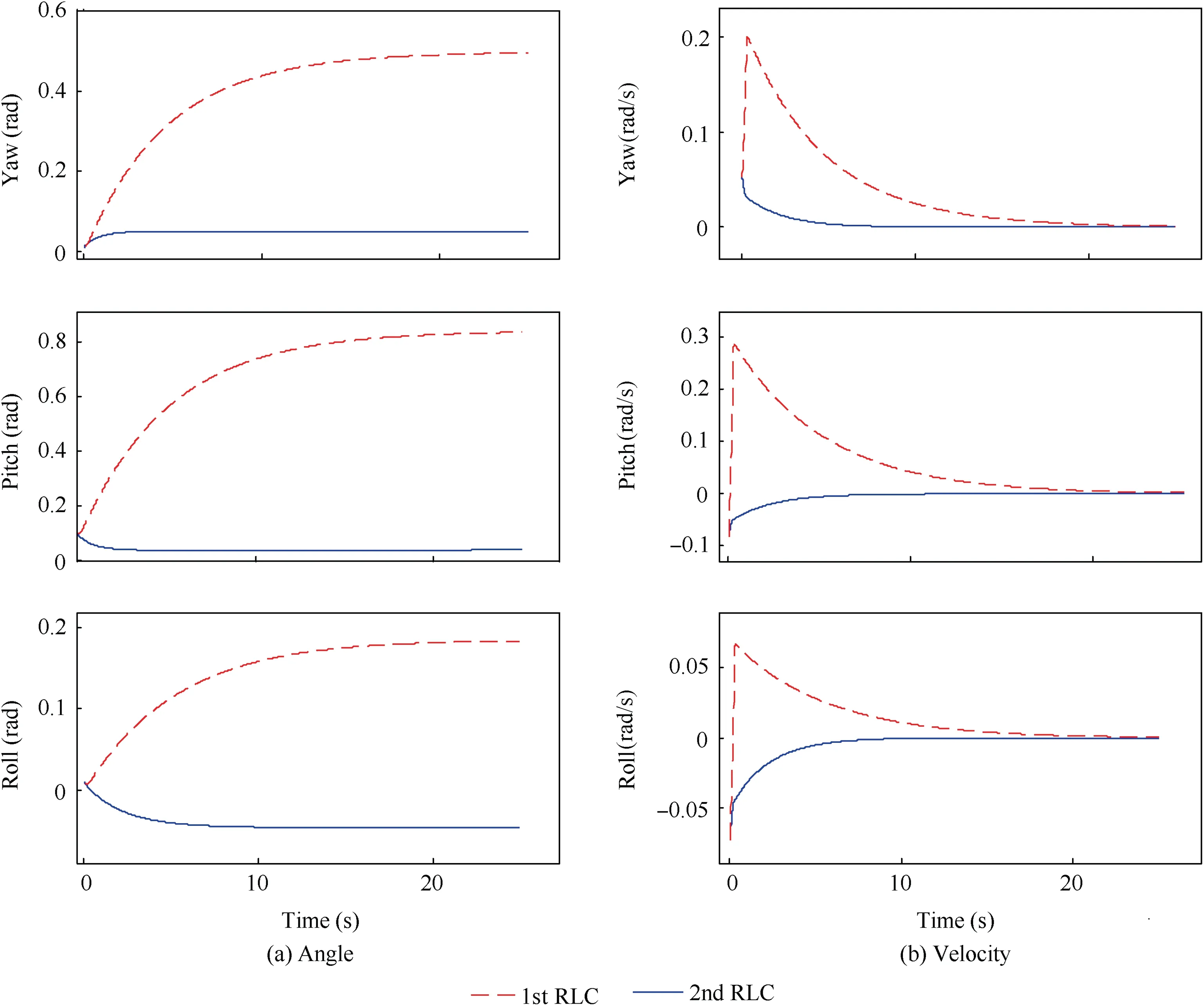
Fig. 12 Comparison of the base satellite attitude with two RLCs.
4. Simulation results
In order to verify the correctness and the reliability of the algorithms proposed in this paper, the simulation results are demonstrated in this section. The simulation is shown in two parts: The first scenario is adopted in Sections 4.1 and 4.2,which consists of a simplified 2D planar scenario to illustrate separately the performance of the parameter estimation and the new controller design. In Section 4.3, a 3D mission scenario is taken into consideration and the integrated hybrid post-capture control framework is tested as a whole.
4.1. Test of hybrid post-capture control framework, planar case
The first simulation case is a planar case which is confined in the x-z plane of Oe-XeYeZe. This kind of simplified simulation scenario has been adopted by many works.11,13,15,16The first simulation is dedicated to test the effectiveness of the hybrid post-capture control framework. The comparison is made between the proposed algorithm and the Model Reference Adaptive Control (MRAC),29which can also stabilize the system by considering the complex contacting dynamics as an external disturbance and canceling it out by an error feed forward method.30In order to implement the MRAC, the upper and middle parts of Eq.(40)are considered as the reference dynamic model. The lower part of Eq. (40) is seen as the disturbance model,which should be cancelled out by the adaptation law. The parameters of the system are listed in Table 2.The simulation results are shown in Figs. 4-6.
From Figs. 4-6, it can be seen that both controllers can properly stabilize the system with parameter uncertainty.However, the relative displacement and velocity between the target and the end-effector obtained by the MRAC controller are much higher than that of the hybrid controller.To this reason, the disturbance of attitude of the base is dramatically reduced by the hybrid control framework, as shown in Fig. 6. This is due to the fact that the hybrid controller seeks to maintain the system’s geometrical configuration.Therefore,the simulation result shows the advantage of algorithms proposed in this paper.
4.2. Test of the parameter estimation algorithm, planar case
The second simulation is to test the effectiveness of the extended state observer. Most parameters remain the same as those used in the previous case except for the modified ones shown in Table 3. The simulation results are provided in Figs. 7-10.
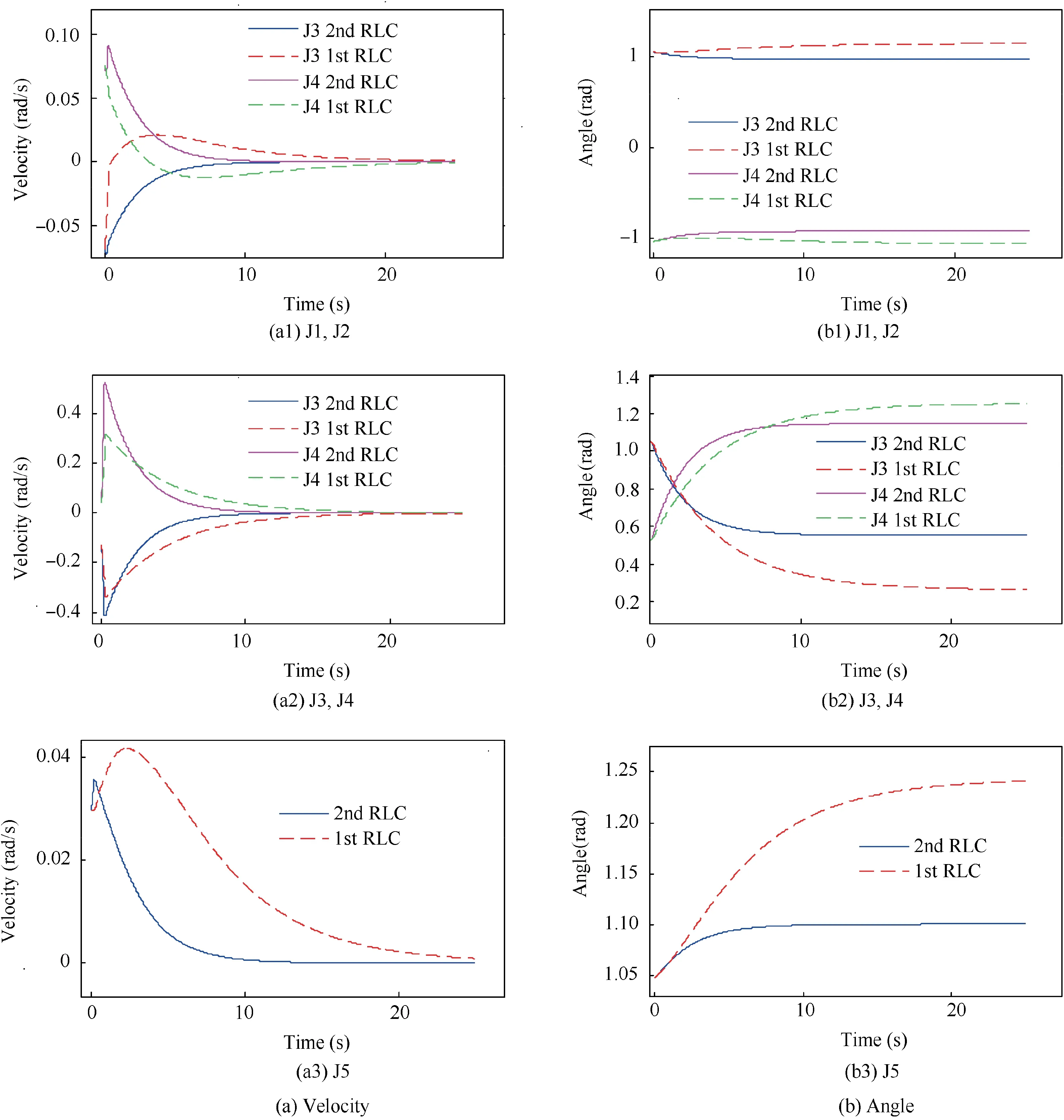
Fig. 13 Comparison of the manipulator joint motion with two RLCs.
From Fig.7,it can be seen that the proposed method is able to estimate and track the time-varying unknown parameters with small error. Fig. 8 shows that the manipulator joints are properly decelerated during the stabilization process. The simulation verifies the correctness of the parameter estimation method and the reactionless control principle. It can also be noticed that the time period of Fig.8 is much longer than that of Fig.7.This is due to the switch between the control modes.According to the discussion in Section 3.3, the parameter estimation algorithm is only called during the first step of the control process.For this reason,the data related to the parameter estimation only exists during the first phase of the mission,which lasts for about 1 s. However, the data related to the motion of the manipulator and the target is shown during the entire control process, which lasts for about 8 second,which causes the difference between Figs. 7 and 8. To further study the influence of measuring noises on the parameter estimation algorithm, Fig. 9 shows the estimation error with different noise levels on the feedback signals of generalized position, velocity, and acceleration of all the system’s DoFs.It can be seen that the estimation error remains within an acceptable margin with a feedback noise level up to 5%.Finally, Fig. 10 shows the comparisons between the proposed algorithm, the linear FFRLSM11and the nonlinear LMS. It can be seen that FFRLSM is able to estimate the target mass and moment of inertia matrix. However, FFRLSM can only estimate the target COM position with considerable amount of error and the convergence seems not being guaranteed.Similarly, with nonlinear LMS, one can estimate the COM position with a long convergence time, while the target mass and inertia matrix can only be extracted with a considerable amount of error. The up-mentioning simulation results demonstrate the robustness of the parameter estimation algorithm proposed in this paper.
4.3. Test of the estimation algorithm and the controller in 3D case
The two previous test cases are realized in a 2D planar environment. To better test the effectiveness of the algorithms, a 3D test case is also proposed. The dynamic parameters of the 3D test case are shown in Table 4,and the mission scenario is illustrated in Fig. 11, the notation J1-J5 denotes the five manipulator joints. It can be seen that a system with 14 DoFs is considered with 6 DoFs for the base satellite,5 manipulator joints,and 3 D relative sliding motion between the end-effector and the target.
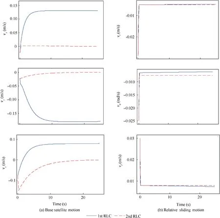
Fig. 14 Comparison of the relative sliding motion and the base satellite motion with two RLCs.
With the up mentioning dynamic parameters, the two ReactionLess Controllers (RLC) proposed in Eqs. (50) and(54) are implemented and tested along with parameter estimation algorithms. The simulation results are shown in Figs. 12-15, respectively.
From Fig.12,it can be seen that since the 1st kind of RLC does not maintain the attitude of the base satellite,the attitude disturbance of the base satellite is much higher than that of the 2nd kind of RLC.This kind of attitude disturbance may cause the problems such as the communication interruption or other safety issue. From Figs. 13 and 14, it can be seen that both RLCs can stabilize the system with a finite horizon, and the relative sliding motion is rapidly decelerated thanks to the null space design. The simulation result verifies the effectiveness of the algorithms proposed in this paper.In Fig.15,I11,I22,I33 denote the target moment of inertia on the three principal axes.From the figures,it can be seen that the proposed algorithm is able to estimate properly all the parameters of the target,including the 3D COM position, the mass and the moment of inertia. For the estimation of the mass and the inertia matrix, the ‘step’ shape curved corresponds to the data accumulation process of the LSM.For the 3D COM position however, it can be seen that the algorithm needs more time to converge to the real values comparing to the results in Fig.10,and the curves illustrated in Fig.15 do not show‘step’shape. This is mainly due to the fact that the 3D components of the COM position are estimated separately in two groups,and the recursive process may reduce the data accumulation period,which can eliminate the step shaped curve.The simulation results prove that the proposed inertial parameter estimation algorithm remains robust and effective in 3D case.
5. Conclusions
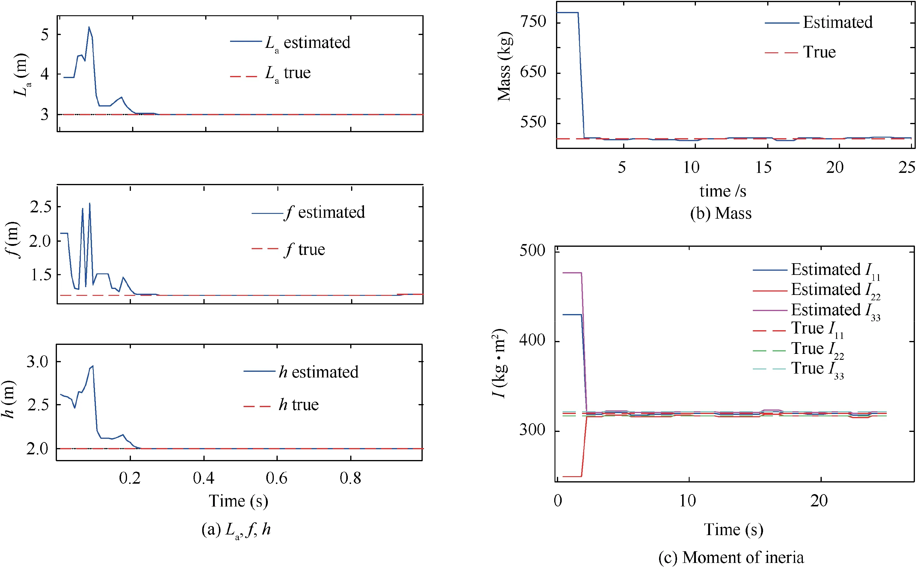
Fig. 15 Comparison of the estimated inertial parameters and its true values.
An inertial parameter estimation algorithm is developed in this paper by using a parameter-explicit representation of the dynamic model. By generating the initial guess of the position of target’s COM, the guessing error and the target mass are estimated successively by an RLMS principle. A hybrid postcapture control algorithm is then proposed with the modified reactionless controller. According to the discussion and simulation results, the following conclusions can be made: (A) the proposed parameter estimation algorithm is efficient and is able to estimate all the inertial parameters of the target considering the UCC. (B) The hybrid post-capture control framework offers a new solution to combined spacecraft stabilization with UCC. (C) The proposed algorithms and methods have some advantage over the classic approaches,especially when the relative sliding motion between the target and end-effector is considered.(D)There still exist some problems to be solved such as the high calculation cost of the algorithm and the possible saturation problem of the actuators.Therefore, more profound study of the combined spacecraft parameter estimation and control problem should be investigated and new results may be reported soon in our future works.
Declaration of Competing Interest
The authors declare that they have no known competing financial interests or personal relationships that could have appeared to influence the work reported in this paper.
Acknowledgments
This work was supported by the National Natural Science Foundation of China (Nos. 11972182,U1637207), sponsored by Qing Lan Project, Funded by Science and Technology on Space Intelligent Control Laboratory (No.HTKJ2019KL502012), and Funded Project of Shanghai Aerospace Science and Technology (No. SAST2017-092).The authors fully appreciate their financial supports.
 CHINESE JOURNAL OF AERONAUTICS2021年3期
- CHINESE JOURNAL OF AERONAUTICS的其它文章
- Criteria for hypersonic airbreathing propulsion and its experimental verification
- Effect of scavenge port angles on flow distribution and performance of swirl-loop scavenging in 2-stroke aircraft diesel engine
- Ship detection and classification from optical remote sensing images: A survey
- Variational method based robust adaptive control for a guided spinning rocket
- Theoretical modeling of vectoring dual synthetic jet based on regression analysis
- Effects of surface roughness on the aerodynamic performance of a high subsonic compressor airfoil at low Reynolds number
