Variational method based robust adaptive control for a guided spinning rocket
Zhongjio Shi , Lingyu Zho ,*, Zhijie Liu
a School of Aerospace Engineering, Beijing Institute of Technology, Beijing 100081, China
b School of Automation and Electrical Engineering, University of Science and Technology Beijing, Beijing 100083, China
KEYWORDS Autopilot design;Guided spinning rockets;Robust adaptive control;Second-order adaptive law;Variational method
Abstract In this paper, a robust adaptive controller is designed for a guided spinning rocket,whose dynamics presents the characteristics of pitch-yaw cross coupling, fast time-varying aerodynamics parameters and wide flight envelop. First, a coupled nonlinear six-degree-of-freedom equation of motion for a guided spinning rocket is developed, and the lateral acceleration motion is modeled as a control plant with time-varying matched uncertainties and unmodeled dynamics.Then, a robust adaptive control method is proposed by combining Bregman divergence and variational method to achieve fast adaption and maintain bounded tracking. The stability of the resulting closed-loop system is proved, and the ultimate bound and convergence rate are also analyzed.Finally, numerical simulations are performed for a single operating point and the whole flight trajectory to show the robustness and adaptability of the proposed method with respect to timevarying uncertainties and unmodeled dynamics.
1. Introduction
Spinning rockets have a series of advantages such as simplifying the structure of the control system, avoiding asymmetric ablation, relaxing the tolerance of manufacturing errors, and improving penetration capabilities. However, traditional uncontrolled rockets cannot satisfy the requirements for the precision strike and range augmentation required by modern warfare. At present, a popular solution is to develop a rocket with guidance&control capability,so that it can rely on guidance and control algorithms to improve the flight performance while maintaining the low-cost characteristics of uncontrolled rockets. Therefore, designing an autopilot with excellent performance is vital to achieving accurate strikes for low-cost guided spinning rockets.
It is also challenging to design autopilots for guided spinning rockets under the constraints of low cost, long-range,and high precision. First of all, the cross-coupling effect between pitch and yaw channel caused by spinning makes the rocket dynamics a multi-input and multi-output coupling system, so that the separate-channel autopilot design method cannot guarantee the strike accuracy of the guided spinning rocket.1-4Then,the dynamics of the rocket shows a wide range of fast time-varying characteristics,which is mainly reflected in the large flight envelope. This requires the autopilot to have the adaptability and robustness to the time-varying system uncertainties.
In recent years, using modern control theory to design autopilots for guided spinning rockets has become the mainstream research direction. Commonly used control strategies include but are not limited to the linear quadratic regulator,5,6dynamic inversion,7and sliding mode control.8,9Gainscheduling is a control method widely used in engineering applications to improve the adaptability of the system to time-varying parameters. The main idea is to select a series of feature points on a typical flight trajectory, calculate the controller parameters at each feature point using traditional autopilot design methods, and then interpolate to schedule the feedback gain to achieve control of the whole flight trajectory.10,11Although this method can improve the adaptability of slow-variable parameter systems, it lacks the theoretical basis to ensure the stability of closed-loop systems, causing control failure for fast-variable systems.12
Robust H∞control is a relatively mature control method that can guarantee the tracking performance when the system model is uncertain. Robust gain-scheduling control method combining robust H∞control and gain-scheduling control is a solution to improve both the robustness and adaptability of the control system.13,14This method not only requires measurable scheduling variables but also needs the derivative of the scheduling variables,which limits the application in actual engineering. Later, design methods of gain-scheduling controllers not depending on derivatives of parameters are proposed to relax the limitation mentioned above.15,16Theodoulis et al. applied robust gain-scheduling control to the autopilot design of a spinning projectile.17,18Although the autopilot showed good robustness and adaptability, when the system parameters change rapidly,the control performance of the closed-loop system cannot be guaranteed.
Adaptive control is a proper method to deal with system uncertainties, and has been used in numerous applications.The core idea of adaptive control is to update the controller parameters online in real time based on the measured system inputs and outputs.The lack of robustness and poor transient performance limit the application of adaptive control in the safety-critical field. Various modified robust adaptive control methods have been proposed to improve the robustness and transient performance of closed-loop systems.19-22Shi et al.applied model reference adaptive control method to the autopilot design of spinning projectiles, and it showed good adaptability to channel cross-coupling and system uncertainties.23,24However, these methods only apply to timeinvariant systems or slow-varying systems, where ideal constant weights satisfy the matching condition so that the perfect cancellation of matched uncertainties can be achieved. Zhang et al. developed an online optimization-based control method with input constraints to handle the time-varying control plant.25The proposed method can update the controller’s parameter at each sampling instant and deal with the strong time-varying uncertainties.Hu et al proposed an adaptive attitude tracking control method for spacecraft considering the time-varying inertia uncertainties.26The proposed algorithm possesses high control accuracy, fault-tolerant capacity and favorable robustness to time-varying inertial parameters.
In this paper,a robust adaptive control scheme is proposed by combining the adaptive control and optimization theory for a guided spinning rocket.During the flight of a guided rocket,the flight velocity and aerodynamic parameters change dramatically so that the existing adaptive control cannot guarantee the tracking performance in the entire flight trajectory. A robust adaptive control scheme based on the variational method is proposed to handle the fast time-varying uncertainties.The contribution of this paper is threefold.First,combining the Bregman divergence and the variational method, a second-order robust adaptive law with a fast convergence rate is proposed.Then,compared with the existing adaptive control method,23,24,27the proposed robust adaptive control method discards the constant-coefficient assumption so that adaptive control can be applied to time-varying uncertain systems.Finally, the Lyapunov stability theory is employed to prove that the proposed method can ensure that the closed-loop system is uniformly ultimately bounded under the fast timevarying uncertainties and external disturbances.
The remainder of this paper is structured in the following manner. Section 2 develops the nonlinear 6-DoF dynamic model for a dual-canard controlled spinning rocket. Section 3 presents the robust adaptive control design procedure based on the optimization theory. Section 4 demonstrates the performance of the proposed robust adaptive control via numerical simulations. Finally, Section 5 concludes this paper.
2. Mathematical model
In this paper, an axisymmetric guided spinning rocket with rotating slender airframe is considered, as shown in Fig. 1.Two pairs of active canards are mounted on the nose of the rocket, acting as the control surface generating maneuver forces and moments to twist and steer the guided rocket. Six canted fins are installed at the tail of the rocket to provide lift and roll moment for the rocket.
To derive the mathematical model of a guided spinning rocket, three relevant coordinate systems, as shown in Fig. 2,are illustrated, namely the earth coordinate system(OXEYEZE), rolling body coordinate system (OXBYBZB), and non-rolling body coordinate system (OXNYNZN). Since the range of the guided rocket is smaller than the radius of the earth,coordinate system OXEYEZEcan be regarded as an inertial coordinate system.
2.1. Kinematic equation
The position of the guided spinning rocket is governed by the following equation23:
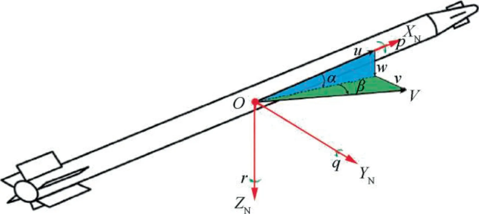
Fig. 1 Airframe configuration of a guided spinning rocket.
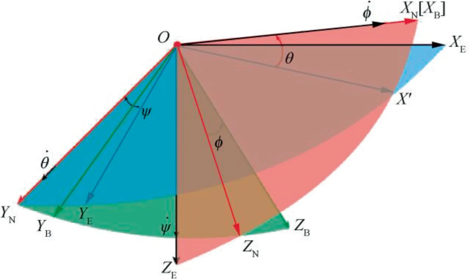
Fig. 2 Sketch of coordinate systems.

where X,Y,Z represent the position of the rocket’s center of gravity (i.e., c.g.) under the inertial frame; u,v,w represent the velocity of c.g. along OXN,OYN,OZN, respectively; θ is the pitch angle; ψ denotes the yaw angle.
The attitude of a rigid body with respect to the inertial frame can be described via Euler angle or quaternions. Since the Euler angle is easy to deduce and more intuitive, yawpitch-roll rotation sequence is adopted to describe the attitude of the guided rocket,

where p,q,r represent the angular velocity of the guided rocket along the axis of the non-rolling body coordinate system; φ denotes the roll angle of the rocket. The definition of the attitude angles is shown in Fig. 2.
2.2. Dynamic equation
According to Newton’s second law of motion, the translation dynamics of the guided rocket under the non-rolling body coordinate system can be expressed as24

where m represents the mass of the rocket, satisfying m=m0- ˙mt, m0is the mass when the rocket is launched,and ˙m is the mass flow rate produced by the engine combustion.Ptis the thrust of the rocket engine. gx,gy,gzare components of the acceleration of gravity g along each axis of the non-rolling body coordinate system, and can be expressed as

Considering the linearized aerodynamics, the aerodynamic forces acting on the slender body are projected onto the nonrolling body coordinate system as
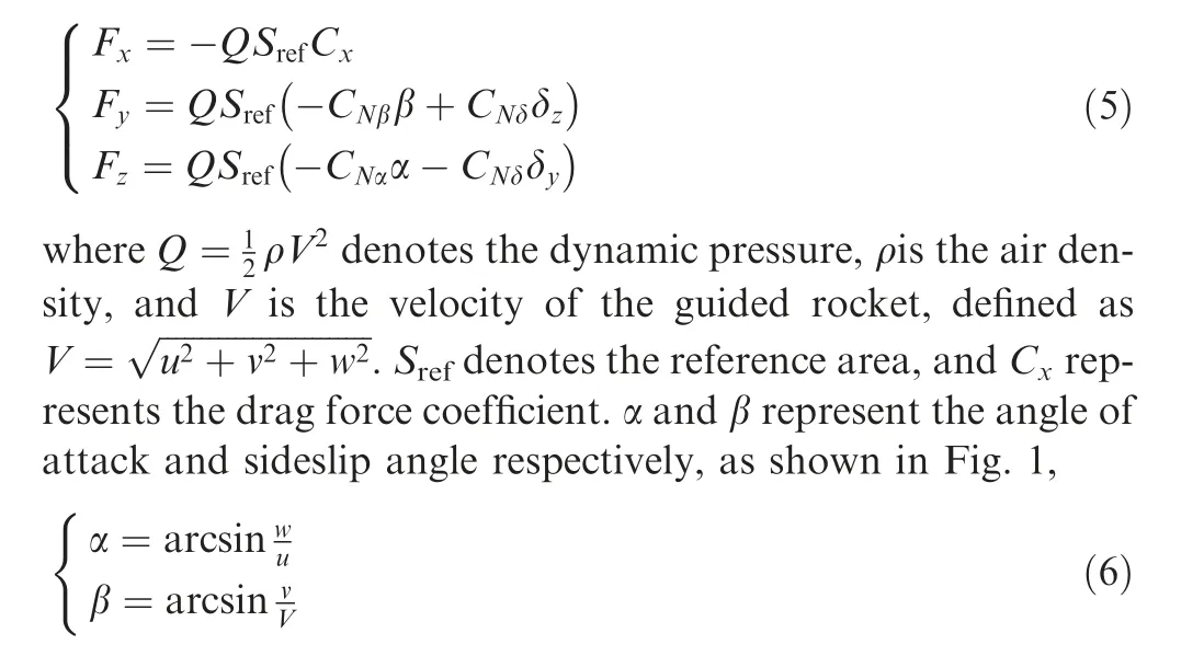
CNαdenotes the partial derivative of the lateral force coefficient to the angle of attack α. Since the configuration of the guided rocket is axisymmetric, we have CNα=CNβ. δy,δzrepresent the canard deflection angles.CNδis the partial derivative of the control force coefficient to the canard deflection angle.
According to the theorem of angular momentum, the rotation dynamics of the guided rocket under the non-rolling body coordinate system can be described as

where Ix,Iyrepresent the polar moment of inertia and the equatorial moment of inertia of the slender body,respectively.Considering the linearized aerodynamics and ignoring the influence of configuration asymmetry, the aerodynamic moment under the non-rolling body coordinate system can be expressed as

where l is the reference length, and δxthe canted angle of the tail fin.Clδx,Clp,Cmα,Cmq,Cmpαand Cmδare the derivatives of the rolling moment coefficient, roll-damping moment coefficient, static stable moment coefficient, damping moment coefficient, Magnus moment coefficient and control moment coefficient, respectively. Due to configuration symmetry, we have Cmα=Cmβ, Cmq=Cmrand Cmpα=Cmpβ.
Combining Eqs. (1), (2), (3) and (7), the six-Degree-of-Freedom (6-DoF) equation of motion describing the guided spinning rocket in the entire flight envelope can be obtained.The guided spinning rocket’s movement in the entire flight envelope is divided into three stages: the boost stage, the free-flight stage, and the guidance & control stage. At the boost stage,the rocket engine starts working,generating thrust to accelerate the rocket to a preset velocity. Then the engine shuts down, and the rocket enters the free-flight stage. At this stage,the rocket climbs to the highest point and then descends to the desired height, where the guidance & control law starts working. At the guidance & control stage, the guidance law calculates the required acceleration command based on the relative motion information between the rocket and the target,and transmits the command to the autopilot. The autopilot then generates the canard deflection to drive the rocket to the target. Therefore, it is necessary to accurately control the acceleration of the rocket to achieve an accurate strike.
2.3. Lateral acceleration equation
During the guided spinning rocket’s flight, the rolling channel is uncontrolled,but canted tail-fins can provide the rolling torque, which is balanced with the rolling damping torque to maintain a stable spinning rate p. Hence, the acceleration autopilot design only needs to be performed in the pitch and yaw channels. Defining the lateral acceleration in the nonrolling body coordinate system as

and assuming that v,w are small,the following equations hold:

Adopting the small and constant coefficient assumptions which are commonly used in the design of autopilot3,9and substituting Eqs. (9) and (10) into Eq. (7), the lateral acceleration equation can be expressed as
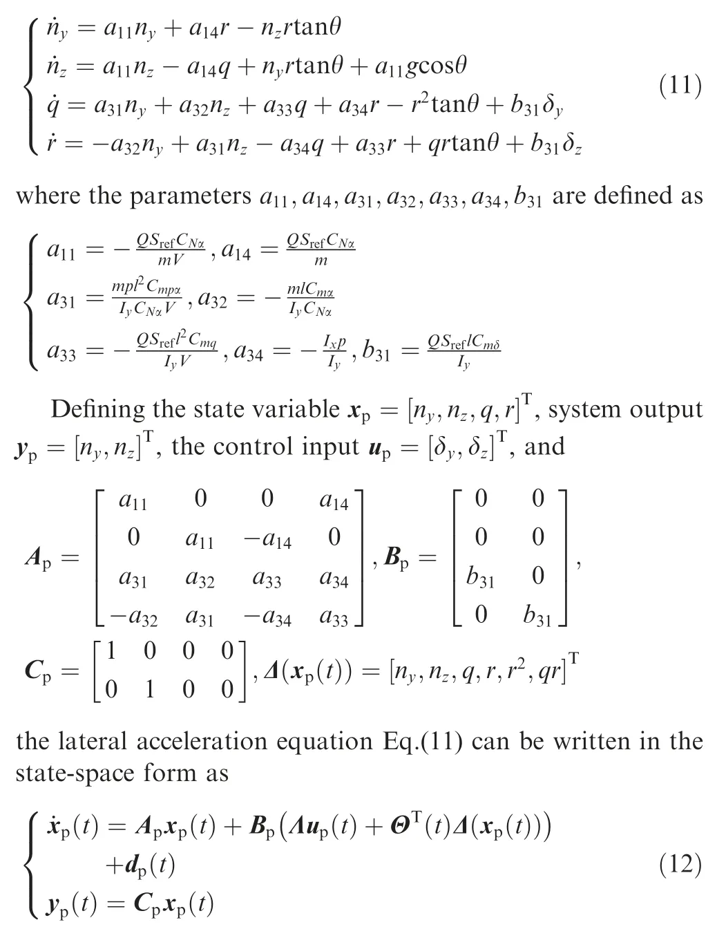
where Λ is a non-singular matrix,which can represent the system uncertainty caused by the uncertain canard control effectiveness; ΘT(t)Δ(xp(t)) represents the matched uncertainty;Θ(t) is a bounded but unknown parameter matrix, which can represent the system uncertainty caused by time-varying aerodynamic coefficients; Δ(xp(t)) denotes the approximation basis function; dp(t) is a bounded unknown vector, which can represent the unmatched uncertainty caused by modeling error and external disturbances.
3. Robust adaptive control based on variational method
In this section, a robust adaptive controller based on the variational method is proposed for a guided spinning rocket.First,the tracking error integral term is augmented into the system state vector to achieve command tracking and resist external disturbances.Then,a robust adaptive controller equipped with a second-order adaptive law is proposed according to the variational method and optimization theory. Finally, the stability of the resulting closed-loop system is proved by adopting the Lyapunov stability theory.
3.1. Tracking error integration
Assuming that the required acceleration computed by the guidance law is ycmd(t), defining the auxiliary system state as

and augmenting the auxiliary state into Eq.(12), then the augmented plant can be expressed as
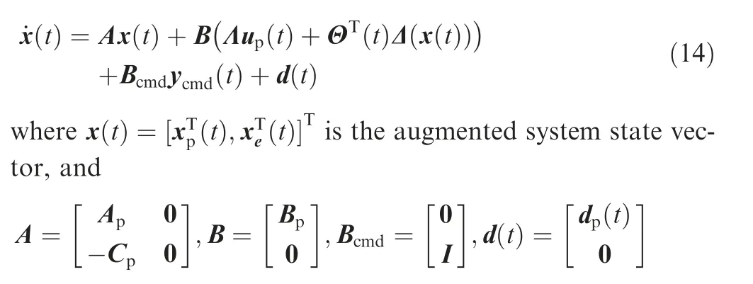
The ultimate goal is to design a control input that can enable the augmented control plant to track the following reference model:

where xm(t) is the state vector of the reference model. Amis a to-be-designed Hurwitz matrix describing the desired system dynamics, and satisfies

where Kxis the state feedback gain.Various linear system controller design methods can be used to design the feedback gain Kx. In this section, we apply the Linear Quadratic Regulator(LQR) design method to the nominal system (when

By selecting appropriate weight matrix Qlqr,Rlqr, the feedback gain matrix Kxcan be obtained using A,B in Eq. (17)with the LQR technique, and then the system matrix Amof the reference model Eq. (15) can be computed according to Eq. (16).
3.2. Controller architecture
The robust adaptive controller designed for the guided spinning rocket consists of two parts: the baseline controller and the adaptive controller,

where the baseline controller is defined as
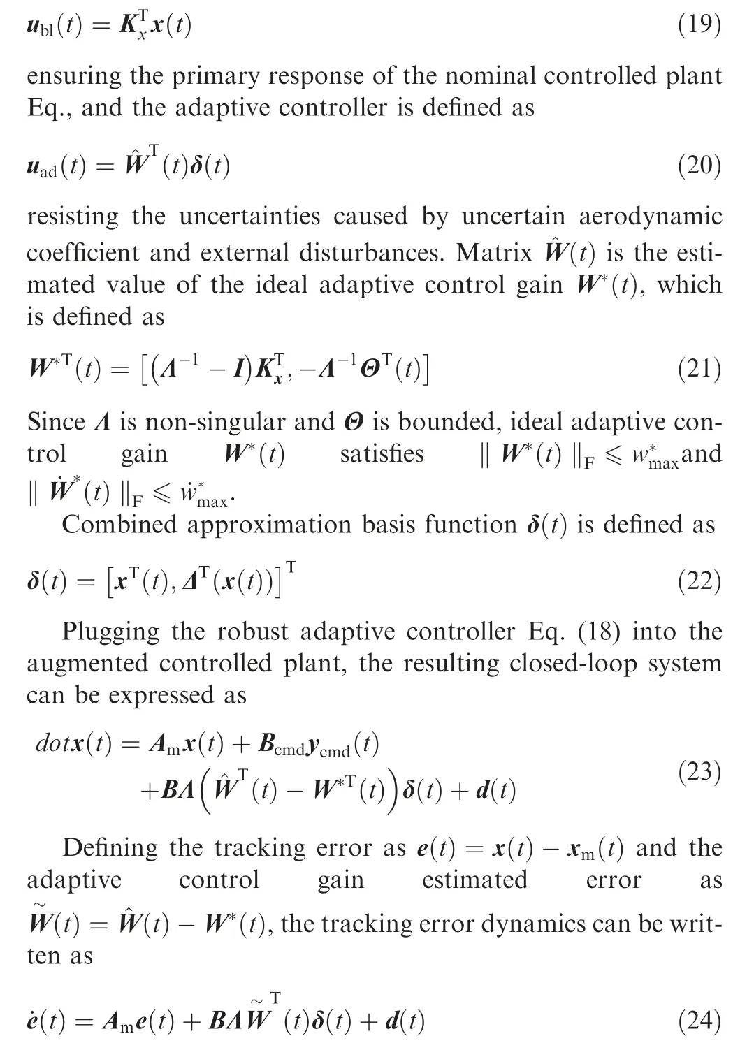
So far, the problem of designing an autopilot for a guided spinning rocket is converted to the problem of selecting an appropriate adaptive law for the estimated value(t)to guarantee the stability of the error dynamics Eq. (24).
3.3. Adaptive law design
In this section, we convert the adaptive law design problem into an optimization problem, and use the variational method to solve the optimization problem to obtain a second-order adaptive law.
First, consider the following optimization problem:
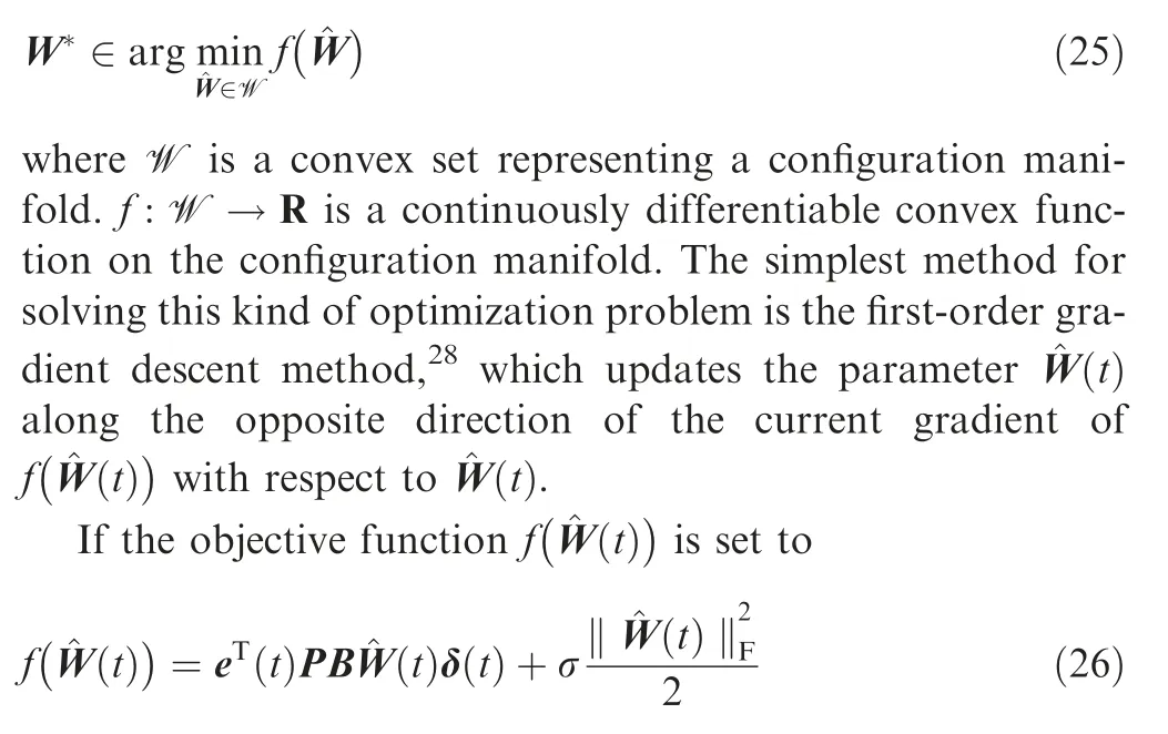
where ‖·‖Fdenotes the Frobenius norm of a matrix. σ is a scalar representing the robust modification parameter. P is a symmetric positive-definite matrix satisfying the following Lyapunov equation:

Then, the naive adaptive law by applying the gradient descent method can be expressed as

where γ is a scalar representing the adaptive gain or the learning rate.
Remark 1. The adaptive law presented in Eq. (29) is the wellknown σ-modification robust adaptive control.29Typically,the adaptive law, assumed or derived by the Lyapunov redesign method, is a differential equation with first-order dynamics.27,30From the optimization perspective, we obtain the same form of adaptive law as the existing method.However, the convergence rate of the gradient-like adaptive law is slow, which will lead to poor tracking performance of the adaptive control system.
In the field of optimization, researchers are committed to improving the gradient-like algorithm to accelerate its convergence rate,and promote the birth of a series of accelerated algorithms, such as Polyak’s heavy-ball method,31Nesterov’s accelerated method20and triple momentum method.32Su found that these accelerated algorithms can be rewritten as a secondorder dynamics in the continuous-time setting.33Therefore, we try to design an adaptive law with second-order dynamics from the optimization perspective to accelerate parameter convergence and improve the adaptive control system’s tracking performance.
Reconsidering the optimization problem stated in Eq. (25),where the objective functionnaturally plays the role of a potential energy,with minima W*at the trough of the potential. Usually we need to design a dynamic process (i.e., adaptive law), so that the estimated parameters can quickly reach the trough. To construct such a dynamic process from the energy perspective, not only the potential energy but also the kinetic energy must be considered.
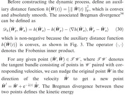
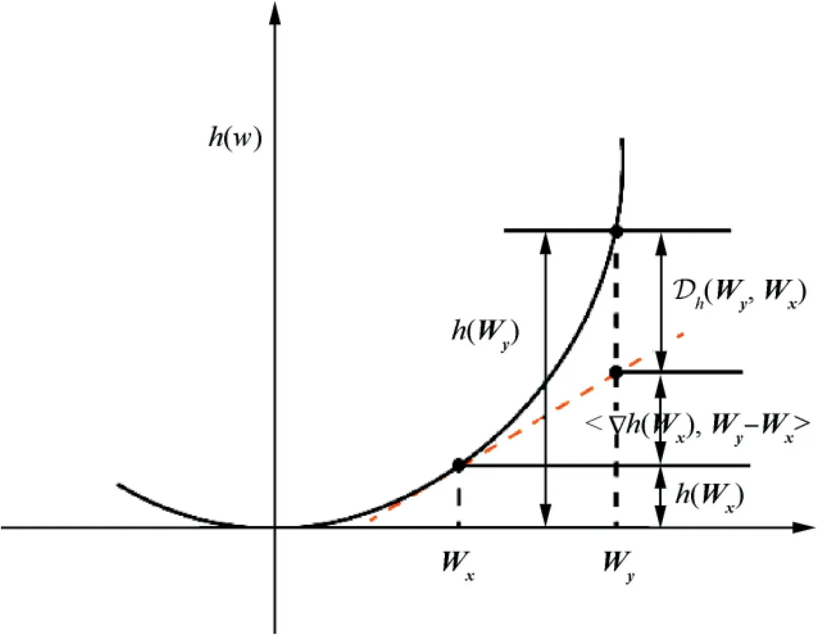
Fig. 3 Illustration of Bregman divergence.
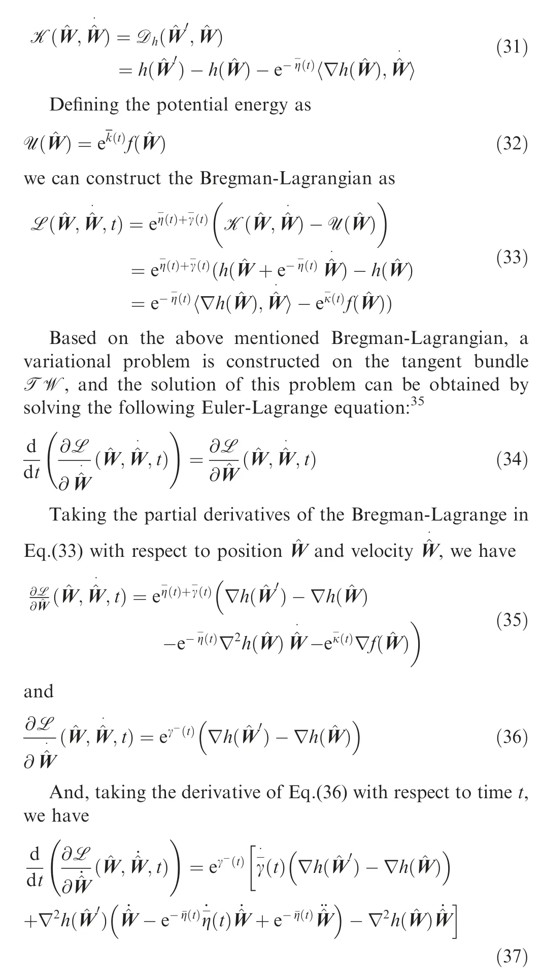
Substituting Eq. (35) and (37) into Eq. (33), we have

which is a second-order differential equation. To simplify the above second-order equation about, the following timevarying functions are defined as

where κ and γ are to-be-designed positive scalars; N(t) is a time-varying normalized function, defined as N(t)=1+δT(t)δ(t).
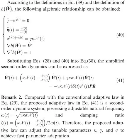
It is worth noting that when implementing the above second-order adaptive law, the derivative of the time-varying normalized function to time t(e.g., N.(t)) needs to be calculated, which is usually tricky. For the convenience of implementation, the second-order differential equation in Eq. (41)may be expressed as the following two cascaded first-order differential equations:

Remark 3. The proposed second-order adaptive law in Eq.(42) can be regarded as a conventional adaptive law Eq. (29)filtered by a first-order low-pass filter with a time-varying coefficient.The low-pass filter can filter out the high-frequency oscillation generated by fast adaption in the conventional adaptive law to realize fast and smooth parameter adaption.

Fig. 4 Block diagram of second-order adaptive law.
The block diagram of the proposed adaptive law can be seen in Fig. 4.
3.4. Stability analysis
The stability of the robust adaptive controller with a secondorder adaptive law can be described by the following theorem:
Theorem 1. Consider a closed-loop adaptive system constructed by the control plant in Eq. (14), reference model in Eq. (15), adaptive controller in Eq. (18) and the second-order adaptive law in Eq. (42). The tracking error e(t) and the adaptive control gain estimated error(t) are uniformly ultimately bounded.
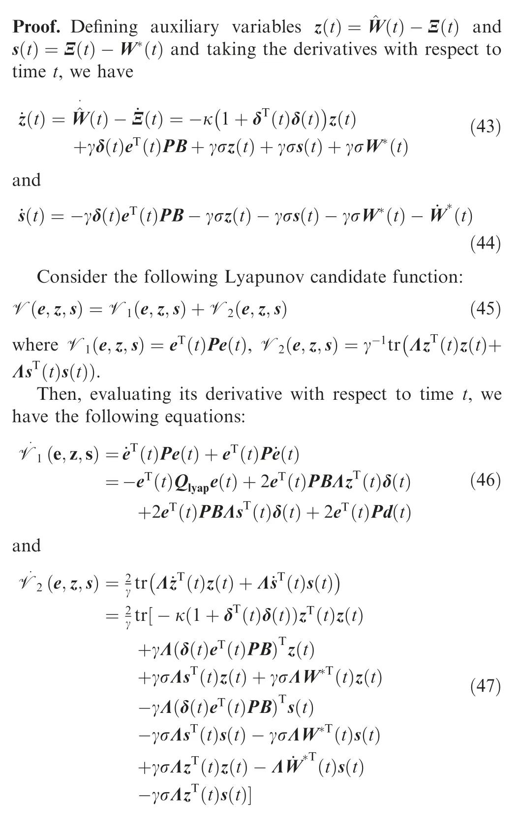
which can be simplified by merging similar items
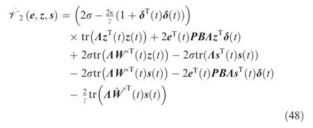
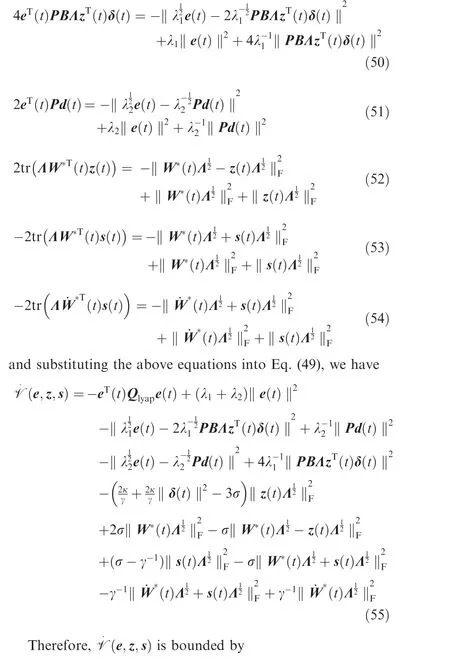
Substituting Eqs. (46) and (48) into Eq. (45), the time derivative of the Lyapunov candidate function can be expressed as

Completing the square yields
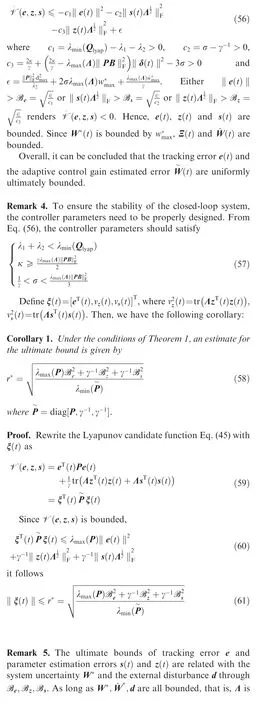

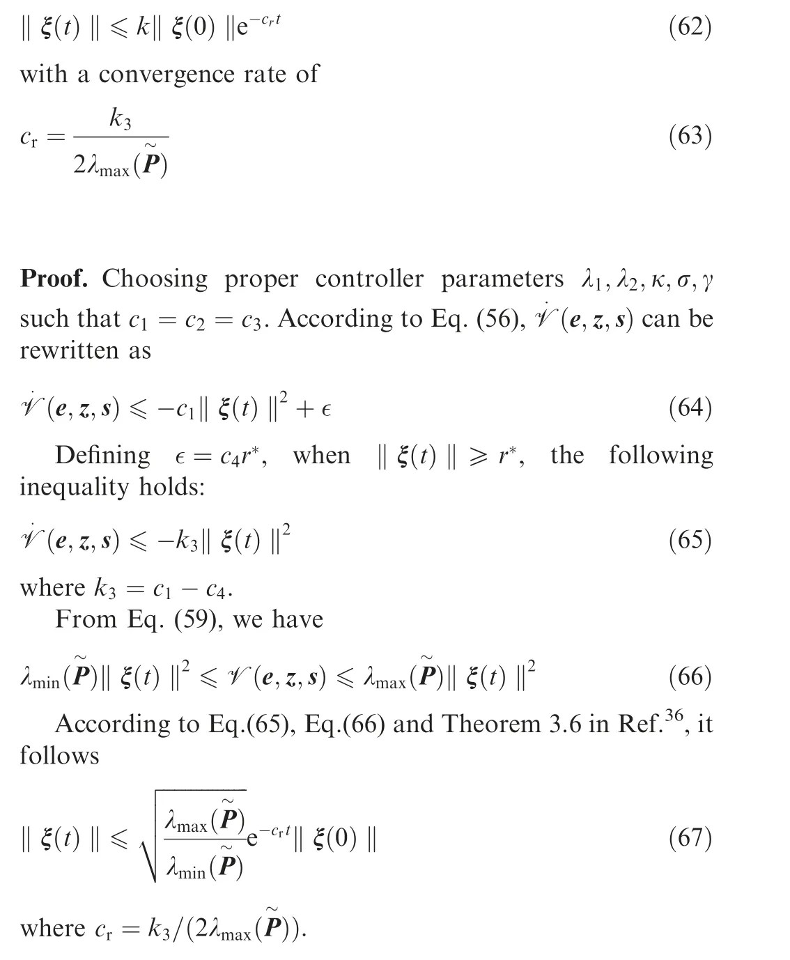
Corollary 2. Under the conditions of Theorem 1, ξ(t)approaches the ultimate bound r*exponentially in time according to
4. Case study
In this section, numerical simulations are performed to verify the proposed robust adaptive controller with second-order adaptive law. First, the robustness of the proposed algorithm and the self-adaptability to system uncertainties are verified by a single-point numerical simulation based on the lateral acceleration equation. Then, the proposed algorithm is brought into the 6-DoF equation of motion for full trajectory simulation. The simulations are performed in MATLAB R2020a with a 64-bit processor, 32 GB memory, and 0.001 s time-step.
4.1. Single point acceleration tracking
The nominal plant considered in this section is the nonlinear lateral acceleration model of a guided spinning rocket at the start point of the guided stage with the speed V of 581 m/s and the altitude Z of-5000 m.The nominal model considered in this section is the lateral acceleration dynamics model of the guided rotating rocket at the starting point. All parameters used to calculate the nominal model coefficients, i.e., entries in matrices A and B, are given in Table 1.
The acceleration command ycmd(t) is set to a square wave with frequency of 0.5 Hz, with an amplitude of 1 m/s in the nychannel and the nzchannel. To simulate the uncertainty experienced by the guided spinning rocket, the bias for a31,a32,a33,a34is set to 50%, and vary between -50% and 50% at a frequency of 1 Hz. Moreover, consider 20% failure of the canard control efficiency, i.e., Λ=0.8I.
The baseline controller ublis designed with weight matrices Qlqr=diag([0.1,0.1,10,10,10,10]) and Rlqr=diag([10,10]).For the proposed adaptive part uad, matrix P is obtained by solving the Lyapunov equation Eq. (27) with Qlyap=I. The adaptive gain γ=10 results in κ=267 and σ=10.All the estimated control values are set to zero for the simulation.
Simulation results are illustrated in Figs.5-7.In Fig.5,the guided spinning rocket’s tracking performances with the LQR controller and the proposed adaptive controller are compared.Due to the time-varying system uncertainties, the traditional fixed-gain control method cannot maintain the tracking performance as it does under the nominal plant. Especially when there is a sudden change in the system(at time 0.5 s,1 s,1.5 s),the tracking performance of the system drops sharply. However,the method proposed in this paper can maintain excellent tracking performance when there is time-varying uncertainty.Fig. 6 shows the simulation results of the angular rates and the control input of the proposed adaptive controller. Even under the effect of time-varying uncertainty, the angular rates and the control signal are still smooth, because the proposed adaptive law contains a low-pass filter that can filter out high-frequency oscillation components. Fig. 7 shows that the tracking error e(t) and the estimated control gains(t),Ξ(t)are uniformly ultimately bounded.
In order to demonstrate the advantages of the proposed variational method based robust adaptive control,comparison simulations are performed among normal adaptive control,robust adaptive control with σ modification, robust adaptive control with optimal control modification, and the proposed robust adaptive control.
In simulations, 50% aerodynamic uncertainty and 20%control failure are considered. The external commands and the baseline controller are the same as the last simulation.All controller parameters are adjusted to enable the closedloop system to track the reference model output accurately.As shown in Fig. 8, all the four adaptive controllers can force the acceleration of the spinning rocket to track the preset reference model accurately. It can be seen from Fig. 9 that only the proposed adaptive control presents a smooth angular rate response, while the other three methods all have oscillation phenomena, especially the standard adaptive control. From Fig. 10, we can see that only the proposed adaptive control can generate smooth control signals, while the others all havehigh-frequency oscillations that are harmful to the canard.Fig.11 shows the convergence characteristics and boundedness of the estimated control gains for closed-loop systems with different adaptive laws. The standard adaptive law is not robust to the external disturbance, so the estimated gains gradually increase. Although the σ modification adaptive law and the optimal control modification adaptive law can ensure the boundedness of the estimated gains,high-frequency oscillation occurs, which contributes to the oscillation of control signals.The proposed adaptive law can guarantee the boundedness of the estimated gains and restrain the high-frequency oscillations from achieving fast and smooth parameter adaption.
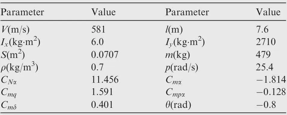
Table 1 Parameters for a guided spinning rocket.
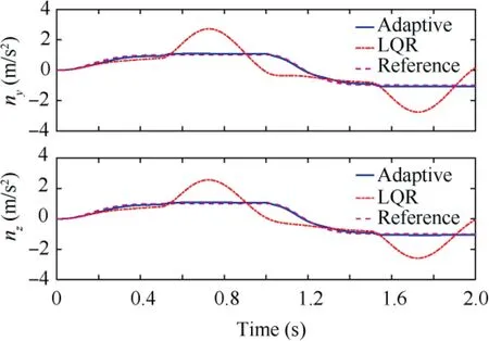
Fig. 5 Tracking performance of lateral acceleration.
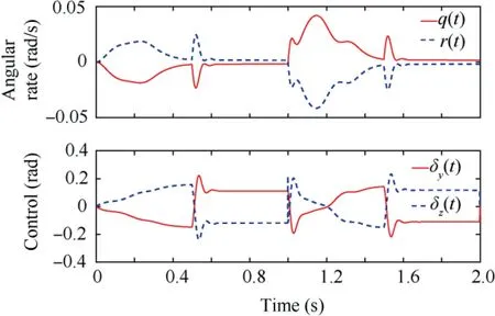
Fig. 6 Response of angular rates and control inputs.
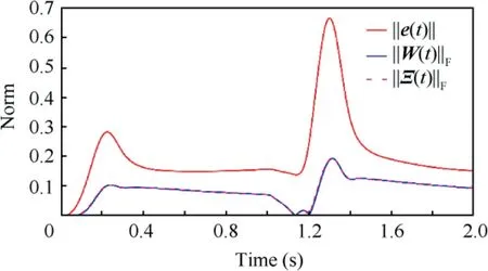
Fig. 7 Norms of tracking error and estimated control gains.
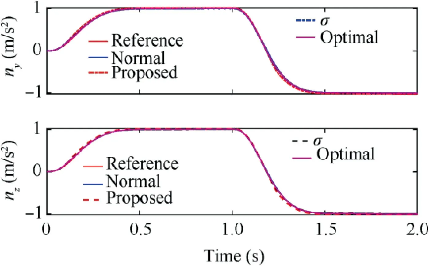
Fig. 8 Tracking performance of different adaptive control methods.
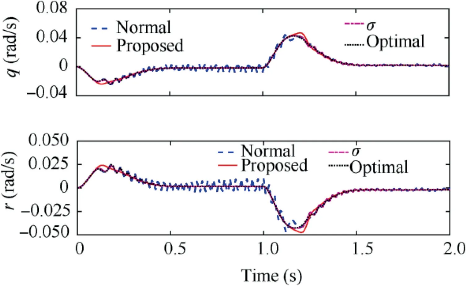
Fig. 9 Responses of angular rates of different adaptive control methods.
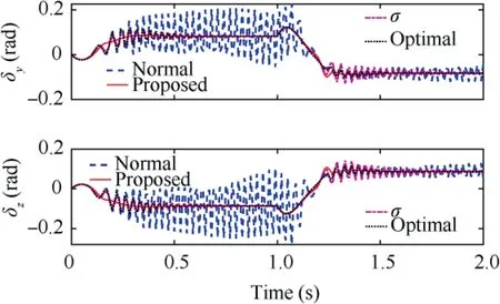
Fig. 10 Control signals of different adaptive control methods.
4.2. Full trajectory simulation
In this section, the proposed adaptive control method is applied to the full 6-DoF nonlinear model developed in Section 2 throughout a whole trajectory simulation.
The rocket launch point is considered as the origin of the inertial coordinate system, and the launch direction points to the target located at(72000 m,0 m,0 m).The initial launching parameters are ψ=φ=0°, θ=45°, u=50 m/s,v=w=0 m/s. The engine thrust and the time-varying mass as well as the time-varying mass moment of inertia are illustrated in Figs. 12 and 13, respectively. All the aerodynamic coefficient derivatives are given in Table 2. During the whole trajectory simulation, the aerodynamic parameters at each moment are obtained by interpolation according to Table 2.In the terminal guidance & control stage, the vector-based three-dimensional proportional guidance law37is used to calculate the required acceleration of the guided rocket.
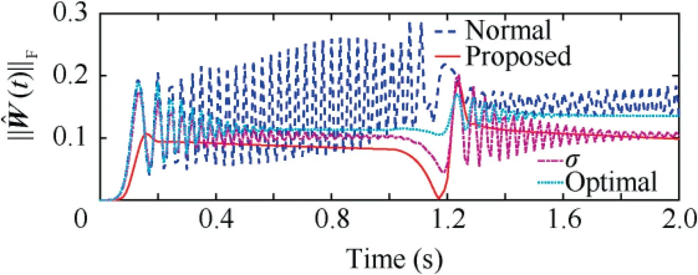
Fig. 11 Norms of the estimated control gains of different adaptive control methods.
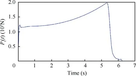
Fig. 12 Thrust of guided spinning rocket.
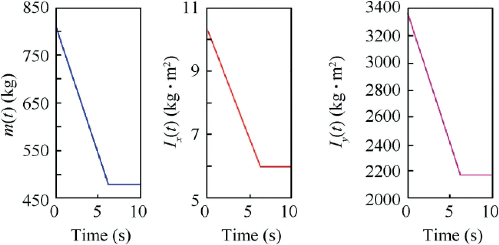
Fig. 13 Mass and moment of inertia of guided spinning rocket.
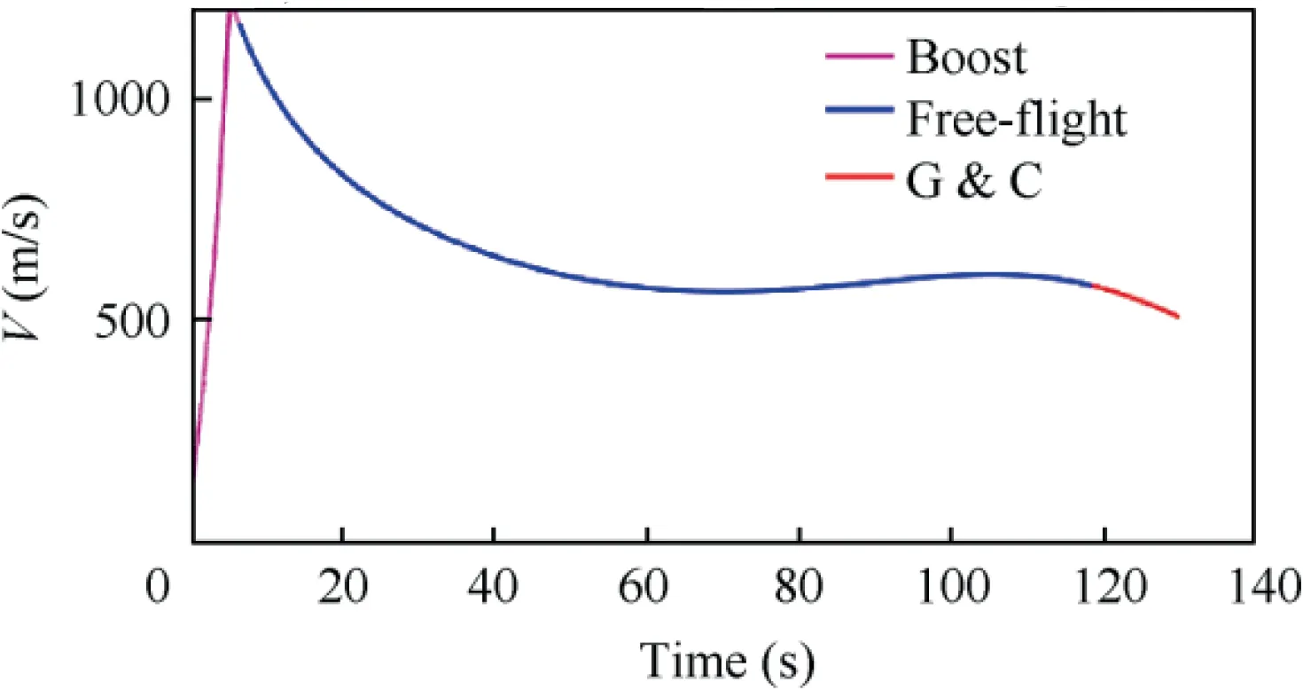
Fig. 14 Velocity of guided spinning rocket.
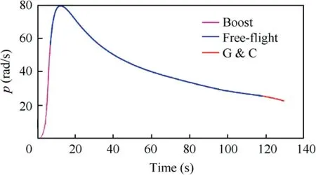
Fig. 15 Spinning rate of guided spinning rocket.
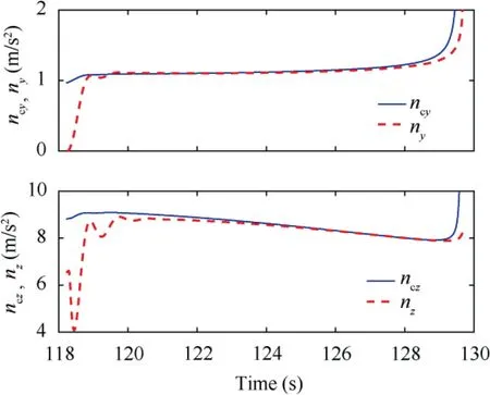
Fig. 16 Acceleration tracking of guided spinning rocket.
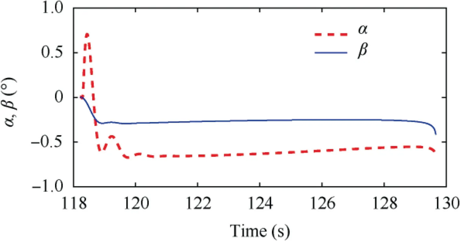
Fig. 17 Angle of attack and sideslip angle at G&C stage.
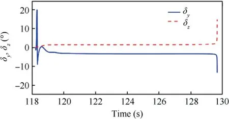
Fig. 18 Canard deflection of guided spinning rocket.
Simulation results are presented in Figs. 14-18. The velocity for the whole trajectory simulation is presented in Fig. 14.At the boost stage, the engine accelerates the rocket to about 1200 m/s. Then the rocket enters the free-flight phase, where the flight speed decreases to 600 m/s. The spinning rate of the uncontrolled roll channel is illustrated in Fig.15.As shown in the figure, the spinning ratepincreases rapidly to 80 rad/s during the boost stage,and decreases gradually to 25 rad/s during the free flight stage. When the flight altitude drops to 5000 m,the rocket enters the Guidance & Control (G&C) stage. The vector-based three-dimensional proportional guidance law starts to work and computes the acceleration commands that can lead the rocket fly to the target according to the relative motion between the rocket and the target. At the same time,the autopilot accepts the acceleration commands from the guidance law to generate the canard deflection commands. It is worth noting that in the terminal guidance & control stage,the flight velocity V,spinning rate p and the flight altitude H of the rocket are all time-varying values, resulting in a timevarying control plant. In the simulation, we treat the differences between time-varying parameters and nominal constant parameters as the time-varying uncertainties of the control plant in the form of. Therefore, the proposed robust adaptive law can be used to design the acceleration autopilot for the time-varying rocket dynamics. The acceleration tracking performance of the guided rocket is presented in Fig. 16.The simulation results show that the acceleration autopilot designed with the proposed robust adaptive control method can force the spinning rocket accurately track the acceleration commands calculated by the guidance law, and achieve the decoupling of the pitch and yaw channels. Since the proposed robust adaptive control method adopts a second-order adaptive law, the high-frequency oscillation caused by estimated control gains fast adaption can be avoided.Hence,the autopilot can generate smooth canard deflection angles and ensure the smooth response of the angle of attack and the sideslip angle, as shown in Figs. 17 and 18.
5. Conclusions
This paper analyzes the design process of traditional robust adaptive control from the perspective of optimization theory,and combines the Bregman divergence and the variational method to design a robust adaptive controller with a secondorder dynamic adaptive law. The proposed adaptive law can be regarded as the σ-modification equipped with a low-pass fil-ter, which can guarantee the tracking performance while achieving fast adaption of time-varying system uncertainties.The proposed method is then applied to the design of the autopilot for a guided spinning rocket. Numerical simulations of a single point and full trajectory show that the proposed method is robust and adaptive to time-varying uncertainties.

Table 2 Aerodynamic coefficients of a guided spinning rocket.
Declaration of Competing Interest
The authors declare that they have no known competing financial interests or personal relationships that could have appeared to influence the work reported in this paper.
Acknowledgement
This study was supported by the National Natural Science Foundation of China (No. 11532002).
 CHINESE JOURNAL OF AERONAUTICS2021年3期
- CHINESE JOURNAL OF AERONAUTICS的其它文章
- Criteria for hypersonic airbreathing propulsion and its experimental verification
- Effect of scavenge port angles on flow distribution and performance of swirl-loop scavenging in 2-stroke aircraft diesel engine
- Ship detection and classification from optical remote sensing images: A survey
- Inertial parameter estimation and control of non-cooperative target with unilateral contact constraint
- Theoretical modeling of vectoring dual synthetic jet based on regression analysis
- Effects of surface roughness on the aerodynamic performance of a high subsonic compressor airfoil at low Reynolds number
