Coordinated attitude control for flexible spacecraft formation with actuator configuration misalignment
Xiomei CHENG, Yun LIU,*, Yi QIN, Feng WANG, Junjie ZHANG
a School of Astronautics, Harbin Institute of Technology, Harbin 150080, China
b China Academy of Launch Vehicle Technology, Beijing 100000, China
c Center for Precision Engineering, Harbin Institute of Technology, Harbin 150001, China
KEYWORDS Actuator configuration misalignment;Adaptive control;Attitude control;Integral-type sliding mode control;Spacecraft formation flying
Abstract This paper investigates the coordinated attitude control problem for flexible spacecraft formation with the consideration of actuator configuration misalignment. First, an integral-type sliding mode adaptive control law is designed to compensate the effects of flexible mode, environmental disturbance and actuator installation deviation. The basic idea of the Integral-type Sliding Mode Control (ISMC) is to design a proper sliding manifold so that the sliding mode starts from the initial time instant,and thus the robustness of the system can be guaranteed from the beginning of the process and the reaching phase is eliminated.Then,considering the nominal system of spacecraft formation based on directed topology, an attitude cooperative control strategy is developed for the nominal system with or without communication delay.The proposed control law can guarantee that for each spacecraft in the spacecraft formation, the desired attitude objective can be achieved and the attitude synchronization can be maintained with other spacecraft in the formation.Finally, simulation results are given to show the effectiveness of the proposed control algorithm.©2020 Chinese Society of Aeronautics and Astronautics.Production and hosting by Elsevier Ltd.This is an open access article under the CC BY-NC-ND license(http://creativecommons.org/licenses/by-nc-nd/4.0/).
1. Introduction
The complex space environment, the vibration effect of large flexible structures such as solar sails and the installation deviation of actuators have brought large challenges in the design of the spacecraft control system. It has certain theoretical value and engineering significance to study the attitude tracking control method with high reliability and excellent performance.1-8Sliding Mode Control (SMC) is one of the most powerful techniques to deal with nonlinear systems with uncertainties,system parameter perturbations and bounded external disturbances. In the past decade, SMC has been applied broadly in spacecraft attitude control research.9-12
Cooperative attitude control of spacecraft formation is an important research topic for spacecraft formation flying,which plays an important role in many practical formation missions,and it has attracted extensive attention.According to different control strategies, attitude cooperative control can also be divided into the following five categories: leader follower,13-16virtual structure,17-19behavior based,20,21multiple input multiple output and cyclic. For instance, Zhang et al. investigated the attitude coordinated tracking control for a group of rigid spacecraft under directed communication topology.22Zhou et al. studied the finite time attitude synchronization and tracking of a class of rigid spacecraft nonlinear dynamics system.23
The classical SMC approaches, although robust against uncertainties, have some disadvantages. It was stated that the system dynamics might be fragile to uncertainties during the reaching phase in which the system states have not yet reached the sliding manifold.24To deal with the reaching phase problem,the concept of ISMC was proposed in Refs.25-27The basic idea of ISMC is to design a proper sliding manifold so that the sliding mode starts from the initial time instant. As a result, the robustness of the system can be warranted from the beginning of the process and the reaching phase is eliminated.24Various research results of this technique can be found over the last few years. In Ref.28, two optimal position and attitude controllers were proposed for attitude tracking of spacecraft. In the first optimal control law, an inverse optimal and a control Lyapunov function are combined with secondorder ISMC,while the second control law proposes optimizing Lyapunov scheme incorporated with the second-order ISMC.28In Ref.27, an optimal integral-type sliding mode control scheme was proposed for attitude regulation of rigid spacecraft. In Ref.24, two Fault-Tolerant Control (FTC)schemes based on integral-type sliding mode control strategy were proposed to compensate for actuator faults without controller reconfiguration.
Adaptive control is a valid method to overcome the parametric uncertainty, and has been applied to the spacecraft problem when certain system parameters are unknown as many works. Combining the methods of SMC and adaptive control, many effective controllers were designed to solve the attitude control problem of spacecraft.29,30In Ref.31, a novel robust adaptive coordinated attitude control algorithm with no prior knowledge of inertia for spacecraft is proposed to coordinately track the common time-varying reference states.In Ref.32, a modified control law is proposed to solve the anti-unwinding finite-time attitude synchronization control problem, in which the adaptive law is applied to estimate the unknown value online.
Motivated by the above observation, the coordinated attitude control problem for flexible spacecraft formation with the consideration of actuator configuration misalignment will be investigated by an integral-type sliding mode approach.The main contributions of this paper are given as follows:
(1) Based on the integral-type sliding mode technology and the adaptive mechanism, the attitude synchronization problem can be solved in the presence of external disturbance. Compared with the existing results,24,33finitetime stability could be obtained for SFF control with the influence of flexible mode and actuator installation deviation.
(2) A novel attitude cooperative control strategy is proposed, which can solve the attitude synchronization problem of the nominal spacecraft formation system with or without communication delay based on directed topology. Simultaneously, the attitude error will reach small regions in finite time when the sliding mode surface is reached.
(3) The topological structure is assumed to be a directed communication topology in this paper, which is more challenging than the undirected communication topology.
The rest of the paper is organized as follows.Section 2 formulates the design problem under investigation; in Section 3,an integral sliding mode control scheme is designed to compensate the influence of flexible mode, external interference and actuator installation deviation in the model, the nominal system of spacecraft formation based on the directed topology is obtained, and the attitude cooperative control strategy is designed for the nominal system with or without communication delay; in Section 4, simulation examples are provided to illustrate the feasibility of the control algorithm; finally, the conclusions are drawn in Section 5.
2. Problem description
The attitude of spacecraft can be described by the unit quaternion, which is defined as
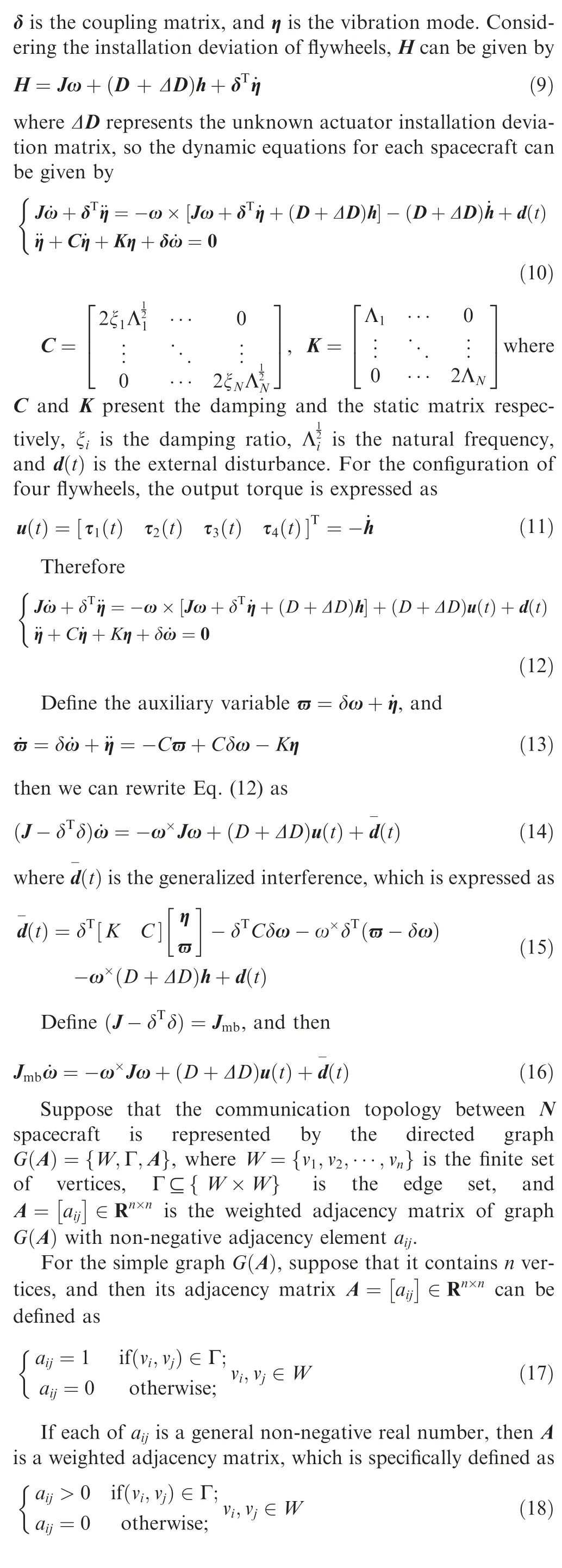
where aijis called the edge weight of (vi,vj), and the corresponding graph is called the weighted graph. The Laplacian matrix of graph G is defined as L=[lij]∈Rn×n

Obviously, the adjacency matrix A and the Laplacian matrix L of the undirected graph G are both real symmetric matrices. In contrast, the digraph is one-way communication,which has less pressure on communication, and the adjacency matrix and the Laplacian matrix of the digraph are asymmetric. Therefore, the digraph topology is more complex and meaningful for the algorithm design.
The following lemmas are given to prove the attitude cooperative stability of spacecraft formation system.
Lemma 1. For the digraph G with N vertices, all eigenvalues of the weighted Laplace matrix L have non-negative real parts.
Lemma 2. Assume M ∈Rm×m,N ∈Rn×n,X ∈Rm×m,Y ∈Rn×n,and then the following results are true:
(1) (M ⊗N)(X ⊗Y)=MX ⊗NY
(2) Suppose that M and N are reversible, and then(M ⊗N)-1=M-1⊗N-1
(3) Let λ1,λ2,...,λmbe the eigenvalues of M and μ1,μ2,...,μnbe the eigenvalues of N,and then the eigenvalues of M ⊗N can be written as λiμj(i=1,2,...,m,j=1,2,...,n).
Lemma 3. For the nonlinear system, ˙x=f(x,u). Suppose that there exists continuous function V(x), and λ>0, α ∈(0,1),0<η<∞, such that

Then, the trajectory of system ˙x=f(x,u) is practically finite-time stable.34
3. Materials and methods
3.1. Integral-type sliding mode controller design
The kinematic and dynamic equations for each flexible spacecraft in terms of the unit quaternion are given by
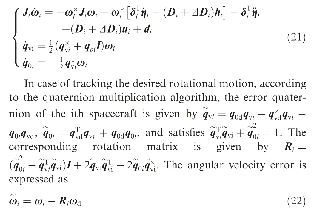
According to the definition of the relative attitude angle and the relative angular velocity, the kinematic and dynamic equations of the relative motion can be obtained:

The following assumptions are made:
Assumption 1. The time of the subsystems in the formation is synchronized.
Assumption 2. At the time of t,when the ith spacecraft and the jth spacecraft are communicating, the quaternion and angular velocity are recorded as qj(t-Tij)and ωj(t-Tij).If there is no communication delay, Tij=0; if there are delays during communication, Tij>0.
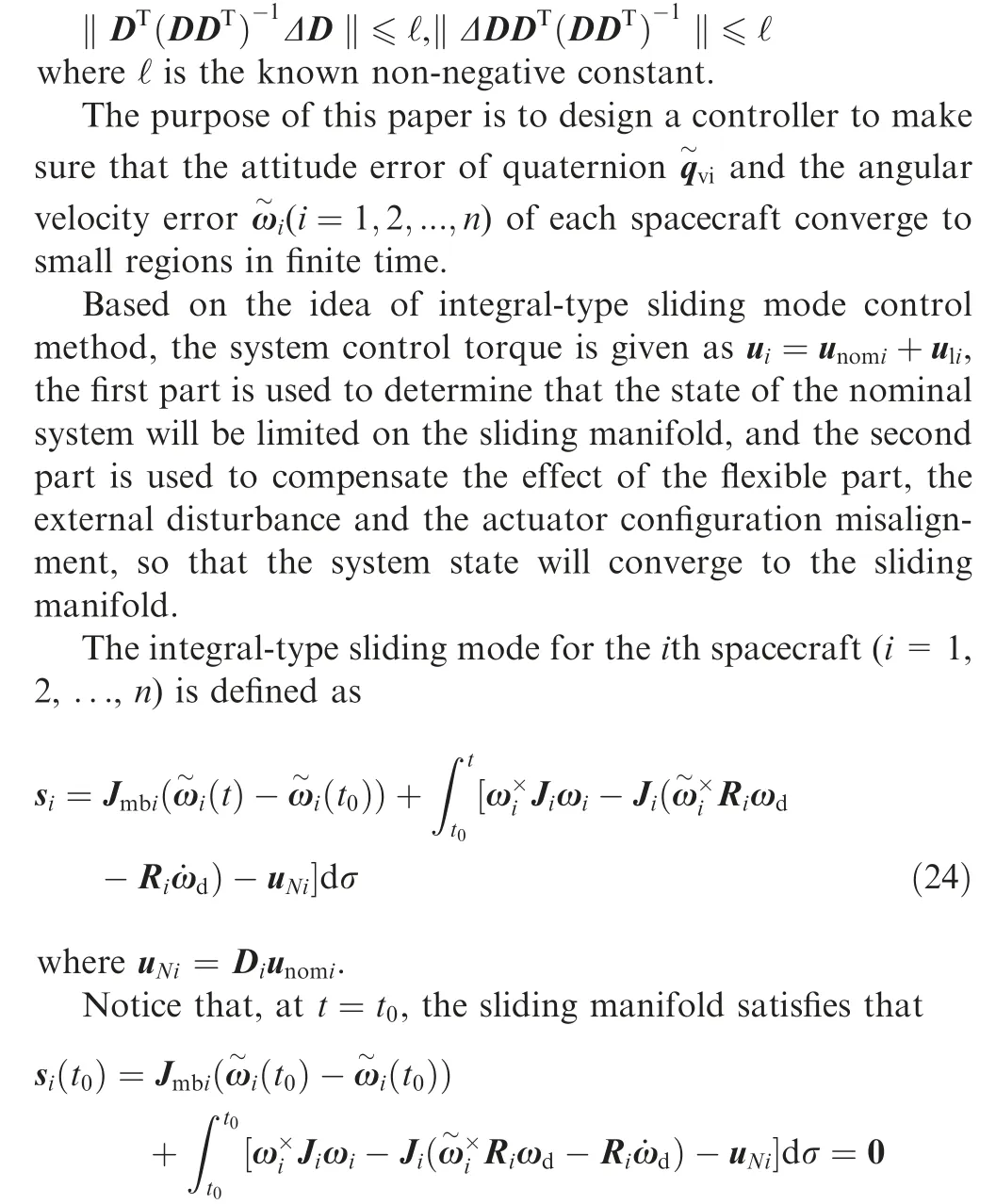
Assumption 5. The uncertain matrixΔDsatisfies that
For the common sliding mode control, the initial value of the system state variable is outside the sliding manifold, then gradually converging to the sliding manifold, and finally sliding on the sliding manifold.24-28The system dynamics might be vulnerable to faults or uncertainties during the reaching phase in which the system states have not yet reached the sliding manifold.24In order to solve this problem, the integraltype sliding mode control method was proposed.24-28The basic idea of ISMC is to design a proper sliding manifold so that the sliding mode starts from the initial time instant.24-28ISMC is widely used due to its advantages.24-28
Based on the basic idea of ISMC, the sliding mode starts from the initial time instant. As a result, the robustness of the system can be guaranteed from the beginning of the process and the reaching phase is eliminated.24
And it can be derived that:
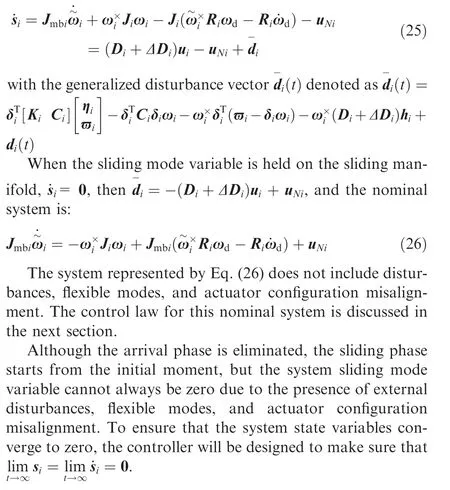
Theorem 1. Assume that the upper limit of the configuration misalignment and the generalized disturbances are known.If the integral sliding manifold (see Eq. (24)) is used, for the spacecraft attitude control system (Eq. (23)) with flexible mode, external disturbances and actuator configuration misalignment, the controller satisfies
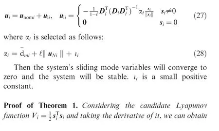
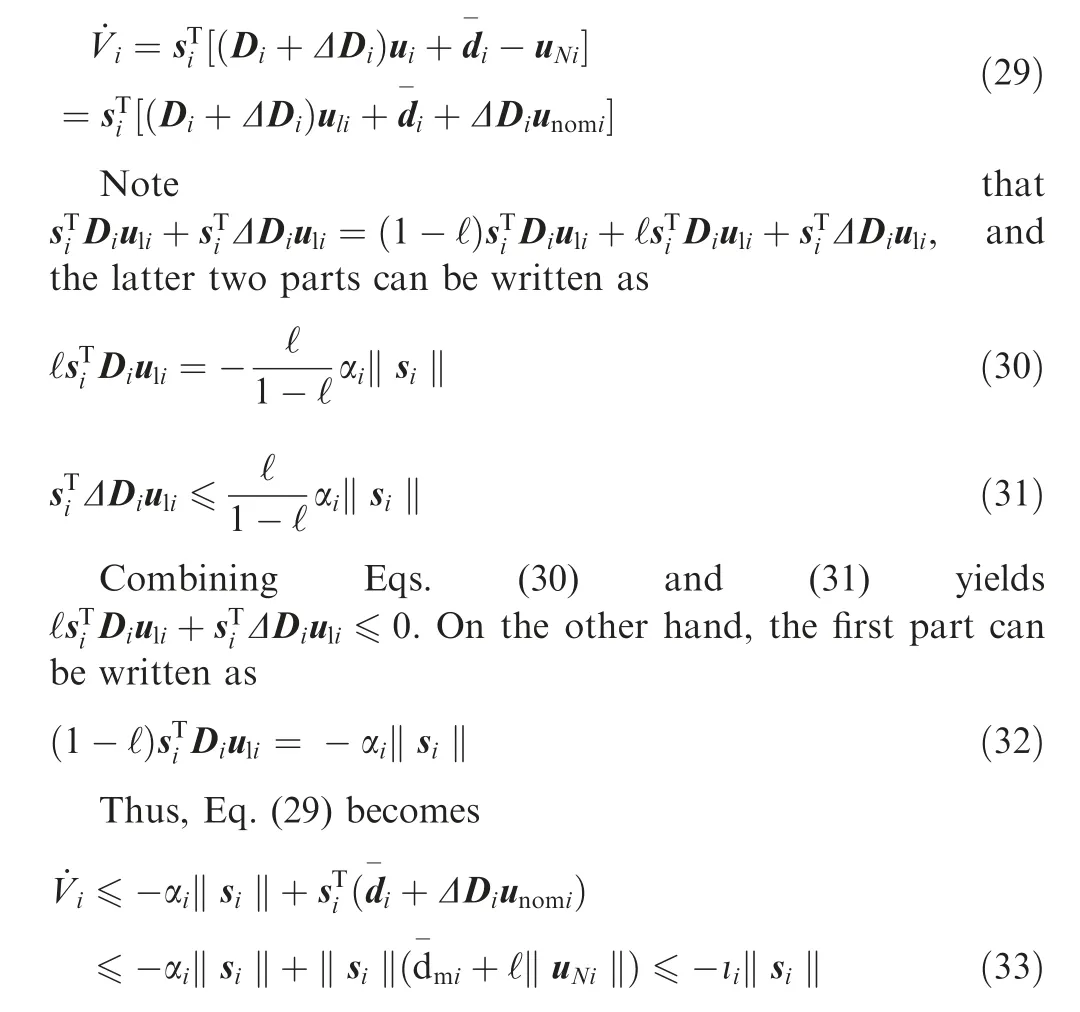
Obviously, ˙Vi≤-ιi‖si‖<0 for si≠0, which means that the sliding mode variable can converge to zero even with the effects of the actuator configuration misalignment, disturbances and flexible mode.
In Theorem 1, we consider the upper bounds of the generalized disturbances and the actuator configuration misalignment as known quantities. But in reality, we may not know the exact value of the upper bounds. Based on the adaptive method, we will revisit the above problem with an adaptive sliding mode control scheme. An adaptive strategy is adopted to estimate the upper bounds.
Theorem 2. Assume that the upper limit of the configuration misalignment and the generalized disturbances are unknown. If the integral sliding manifold (see Eq. (24)) is used, for the spacecraft attitude control system (Eq. (23)) with flexible mode, external disturbances and actuator configuration misalignment, the controller satisfies

where φ is a small positive constant and κi, φi, ξiare design parameters satisfying that (1-ℓ)κi>0, (1-ℓ)φi>0,(1-ℓ)ξi>0.
Then the system’s sliding mode variable can converge to a small area near zero, and the system is practically finite-time stable.
Proof of Theorem 2. . We define the following Lyapunov candidate:

Discuss the following two situations:
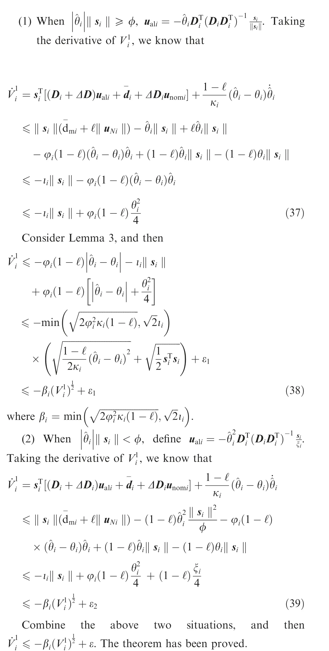
Thus the sliding manifold converges to a small area near zero.
3.2. Nominal control system design
3.2.1. Without communication delay
For the nominal system (see Eq. (26)), this section will design the controller uNifor the case of Tij=0.
In this section, the directed communication topology is used to solve the problem of the spacecraft formation. Define B=diag{B11,B22,···,Bnn}, where

Define the weighted adjacency matrix A=[aij]∈Rn×n,where

Define the Laplacian matrix L=B-A.This paper considers the formation of topology as a directed graph,which means aij≠aji. So L is not a symmetric matrix.
Design the sliding manifold of the nominal system,
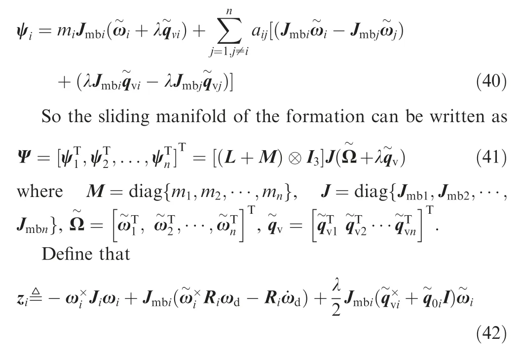
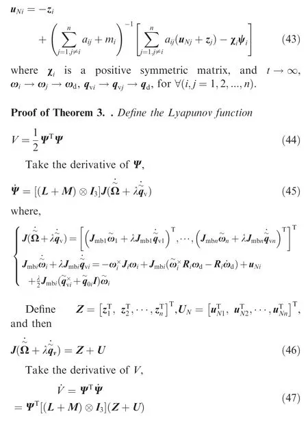
Theorem 3. For the nominal spacecraft attitude error control system(see Eq.(26))without communication delay,considering the communication topology as a directed communication topology, the controller is designed as follows:
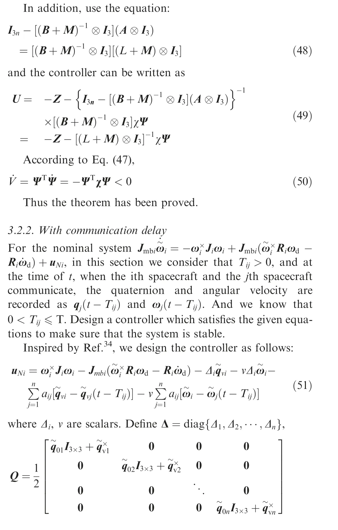
Theorem 4. For the nominal spacecraft attitude error control system(see Eq.(26))with communication delay,considering the communication topology as a directed communication topology with a directed spanning tree,we design the controller as Eq.(51)with v>0 and at least one Δi>0, which satisfies where omax(Ξ), omin(Ξ) are defined as the maximum and minimum eigenvalues of Ξ respectively. For the above controller,when t →∞, ωi→ωj→ωd, for ∀(i,j=1,2,...,n).
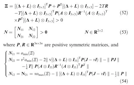
Proof of Theorem 4. Select the Lyapunov function as follows:

Define (Δ+L)⊗I3×3= Φ, take the derivative of V, and then
4. Results and discussion
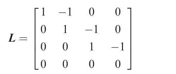
There are four spacecraft in the formation (n=4). The communication topology is line-type as Fig.1.Considering the situations with or without communication delay, we design controllers as Eqs. (43) and (51). In this section, we present practical examples to illustrate the effectiveness of the proposed controllers.
The Laplacian matrix L can be written as
We can define the formation keeping degree and the state keeping degree to present the effectiveness of the above controllers.35The state keeping degree can be written as
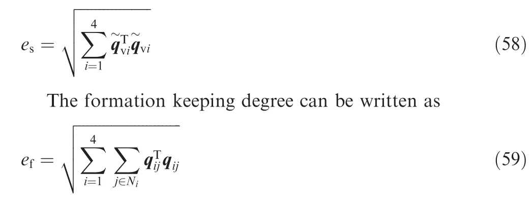
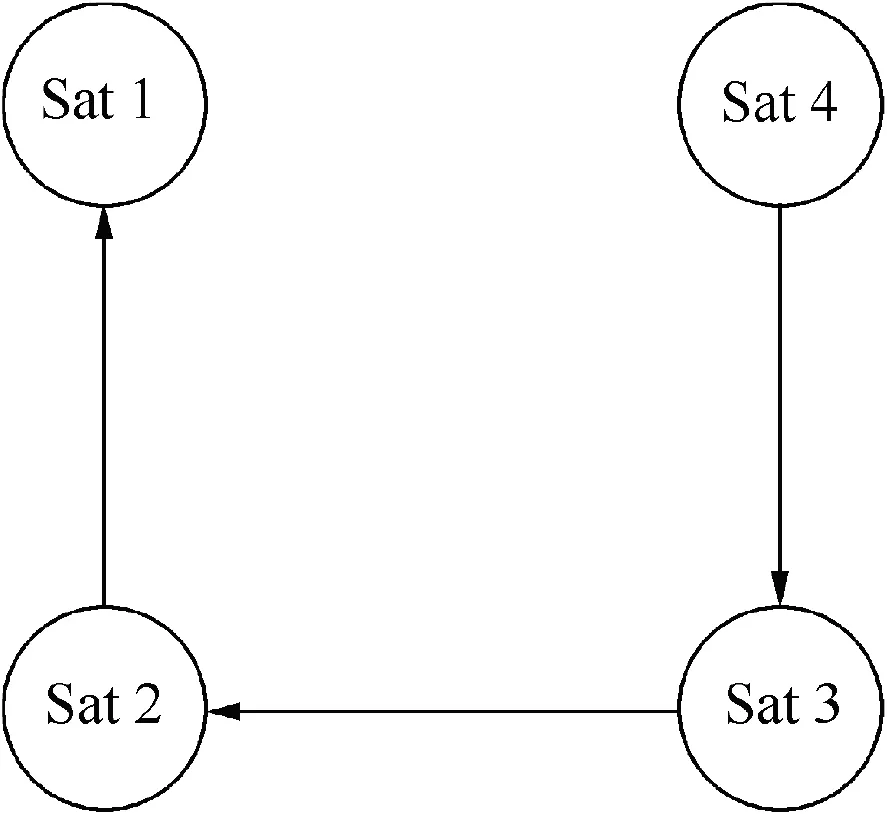
Fig. 1 Interspacecraft-directed communication topology(n=4).
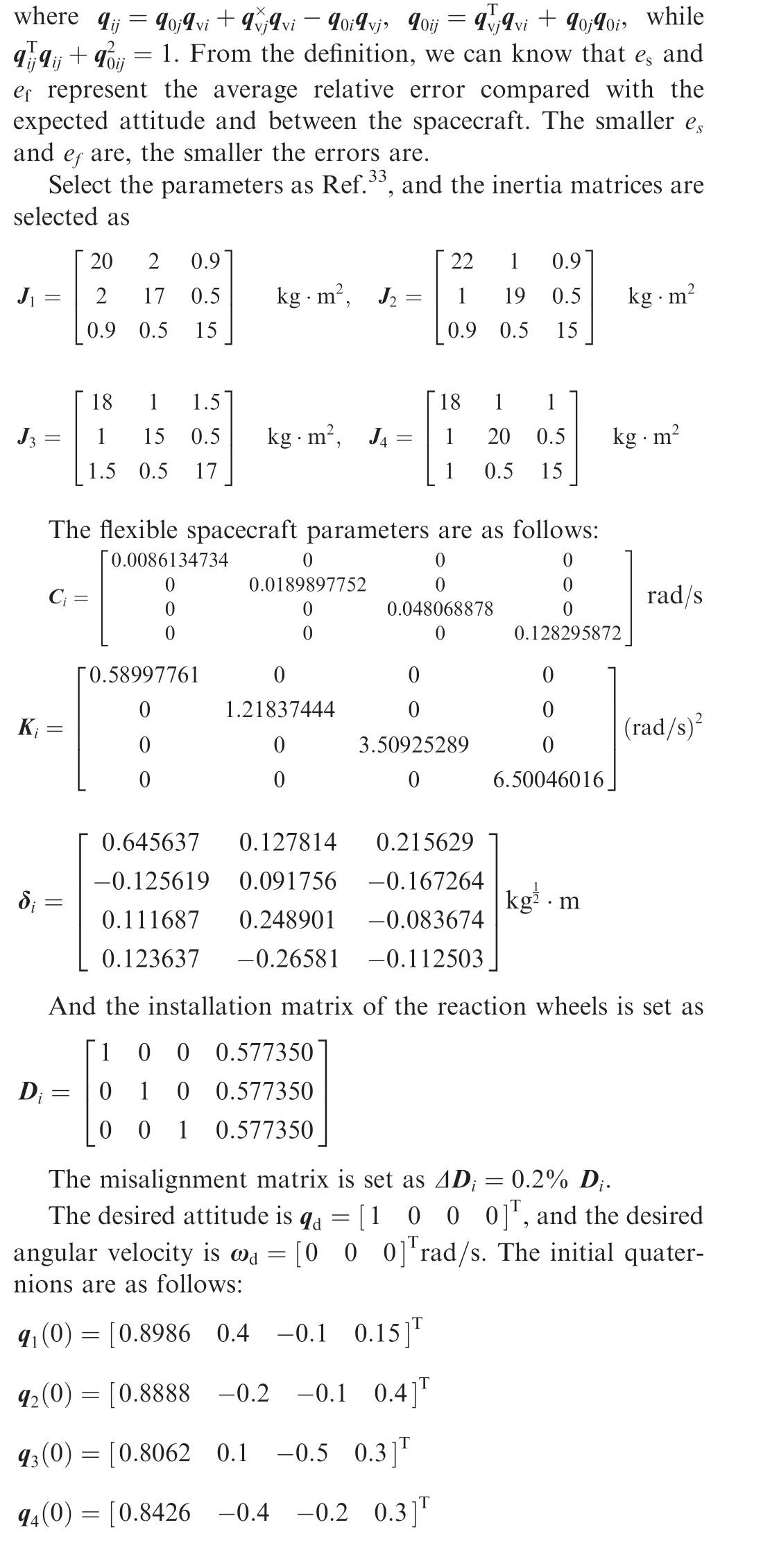
Considering the different controllers defined as Eqs. (34),(43) and(51), we will prove the effectiveness of the controllers by the numerical simulation and analysis of the influence of control parameters on the stability of the system.
4.1. Without communication delay
Choose the parameters κi= 1, φi= 0.00025 of the controller uali, mi=1,χi= I3×3of the controller uNi. We set λ=0.05,λ=0.1, λ=0.5 to see the effectiveness of the controllers.The results are shown in Fig.2.It can be seen that the attitude tracking and formation keeping can be achieved. It is obvious that the formation keeping degree and the state keeping degree converge to 0 respectively at 250 s, 150 s and 25 s under the misalignment of the actuators. Thus we can conclude that the bigger the λ is, the shorter the convergence time is.
When λ=0.5,because all subsystems of the spacecraft formation are similar, there only show two of the spacecraft as examples. Fig. 3 shows the attitude error trajectory and the velocity error trajectory, and it can be seen that the attitude tracking can be achieved under the misalignment of the actuators. From the beginning, it changes a lot, and then it converges to zero slowly.
Choose q~v1,i,q~
v2,ias examples,and Fig.4 shows the relative attitude error trajectory.It can be seen that the attitude tracking can be achieved under the misalignment of the actuators.From the beginning, it changes a lot; at about 20 s, it converges to zero slowly.

4.2. With communication delay
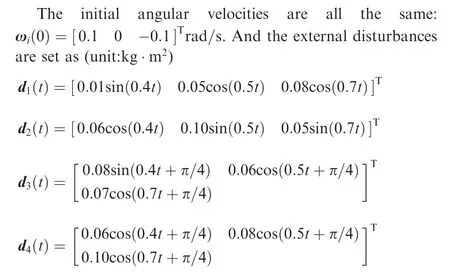
The structure of the formation in this subsection is shown in Fig. 1. The parameters of the spacecraft subsystems are the same as the subsection above.To highlight the controller effect between spacecraft, we choose smaller disturbances:

Choose the parameters κi= 1, φi= 0.00025 of the controller uali, Δ3=5, Δ1=Δ2=Δ4=0 of the controller uNi.The upper bound of Tijis 0.5 s. Observe the effectiveness of the controllers withv=20, v=10, v=5. The results are shown in Fig. 6.
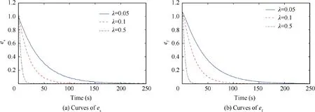
Fig. 2 Curves of es and ef at λ=0.05, 0.1, 0.5.
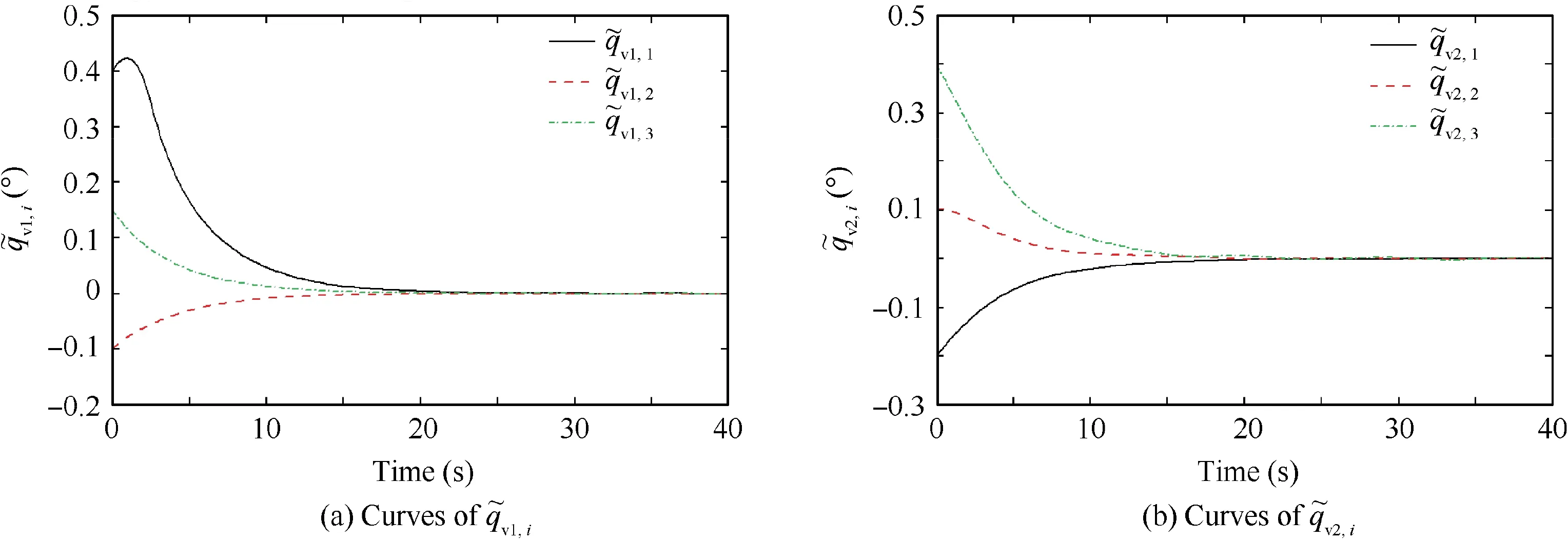
Fig. 3 Curves of and (λ=0.5).
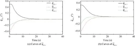
Fig. 4 Curves of and (λ=0.5).
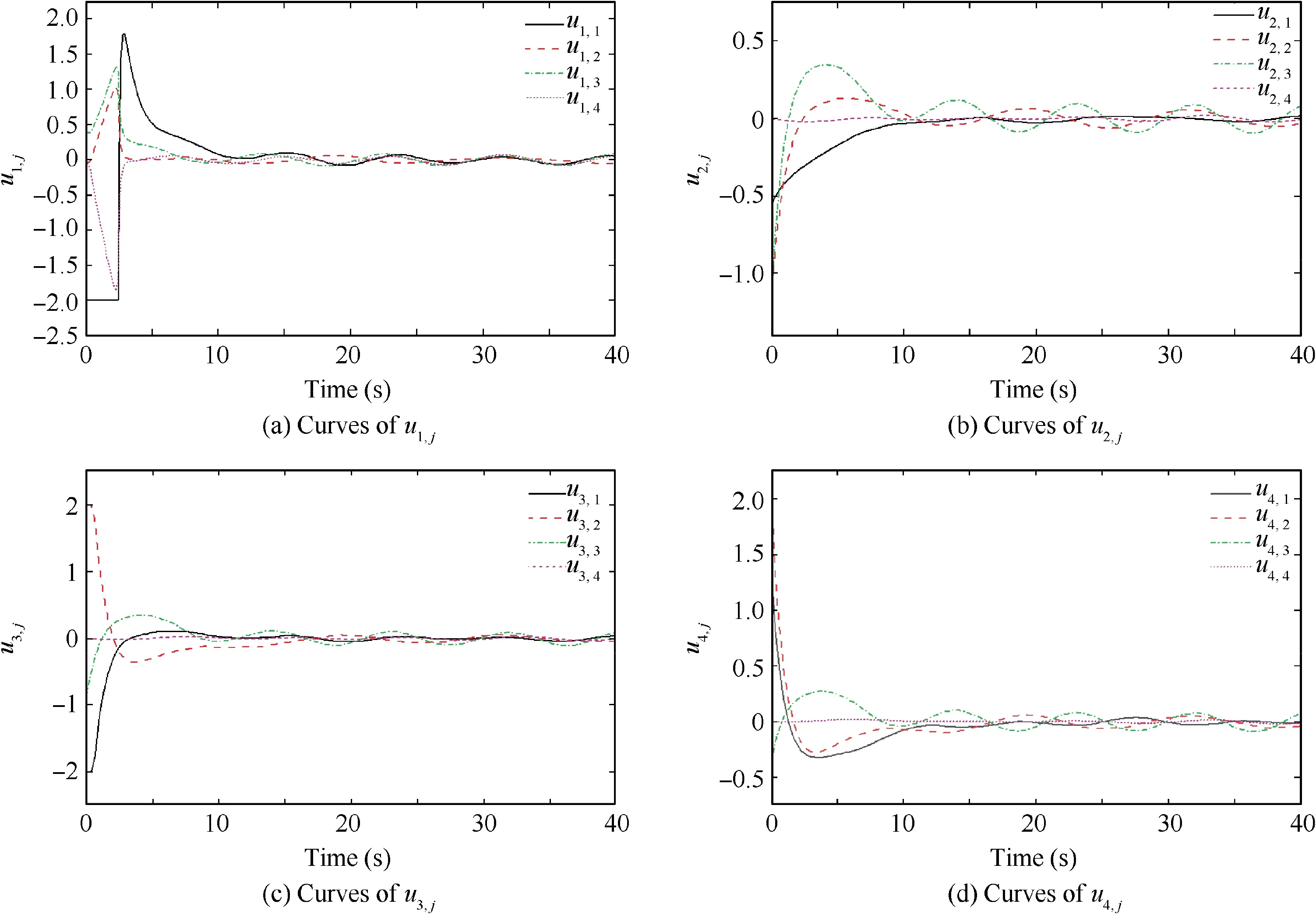
Fig. 5 Curves of u1,j, u2,j, u3,j and u4,j (λ=0.5).
It can be seen that the attitude tracking and formation keeping can be achieved. It is obvious that the formation keeping degree and the state keeping degree converge to 0 respectively at 250 s, 110 s and 70 s under the misalignment of the actuators. Thus we can conclude that the smaller the v is, the shorter the convergence time is. When v=5, the changes of these important indicators are as follows:
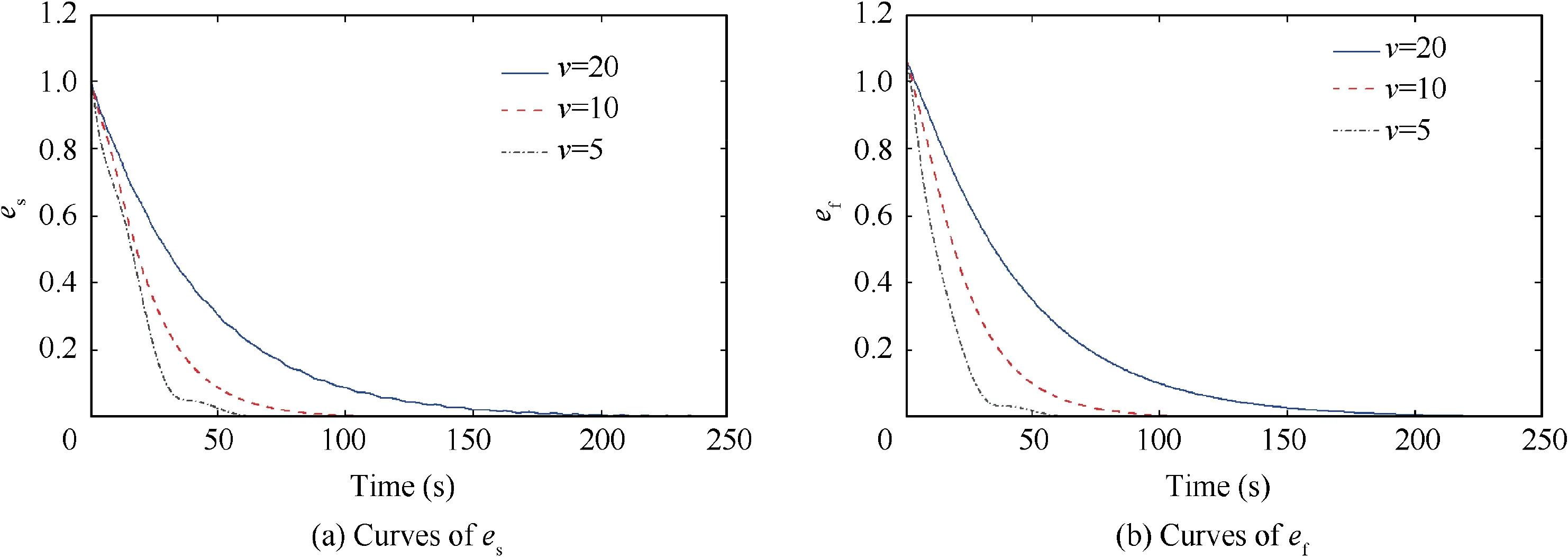
Fig. 6 Curves of es and ef at v=20, 10, 5.
From Fig.1 and the control parameters,we can see that the communication topology between the formation spacecraft is a directed graph. Only Sat 3 is absolutely controlled, and Sat 1,Sat 2 and Sat 4 only rely on the synergistic control torques between the spacecraft in the controller (see Eq. (51)). From Figs.7 and 8,although Sat 1,Sat 2 and Sat 4 need longer time to reach the stability of the attitude and angular velocity error,they only rely on the synergistic control torques between the spacecraft to get the attitude tracking achieved.From the simulation of this section, it can be concluded that, with communication delay,the spacecraft attitude and angular velocity can converge to zero and the relative attitude between spacecraft can also be well synchronized.
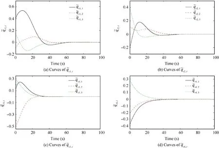
Fig. 7 Curves of q~v1,i, q~v2,i, q~v3,i and q~v4,i (v=5).
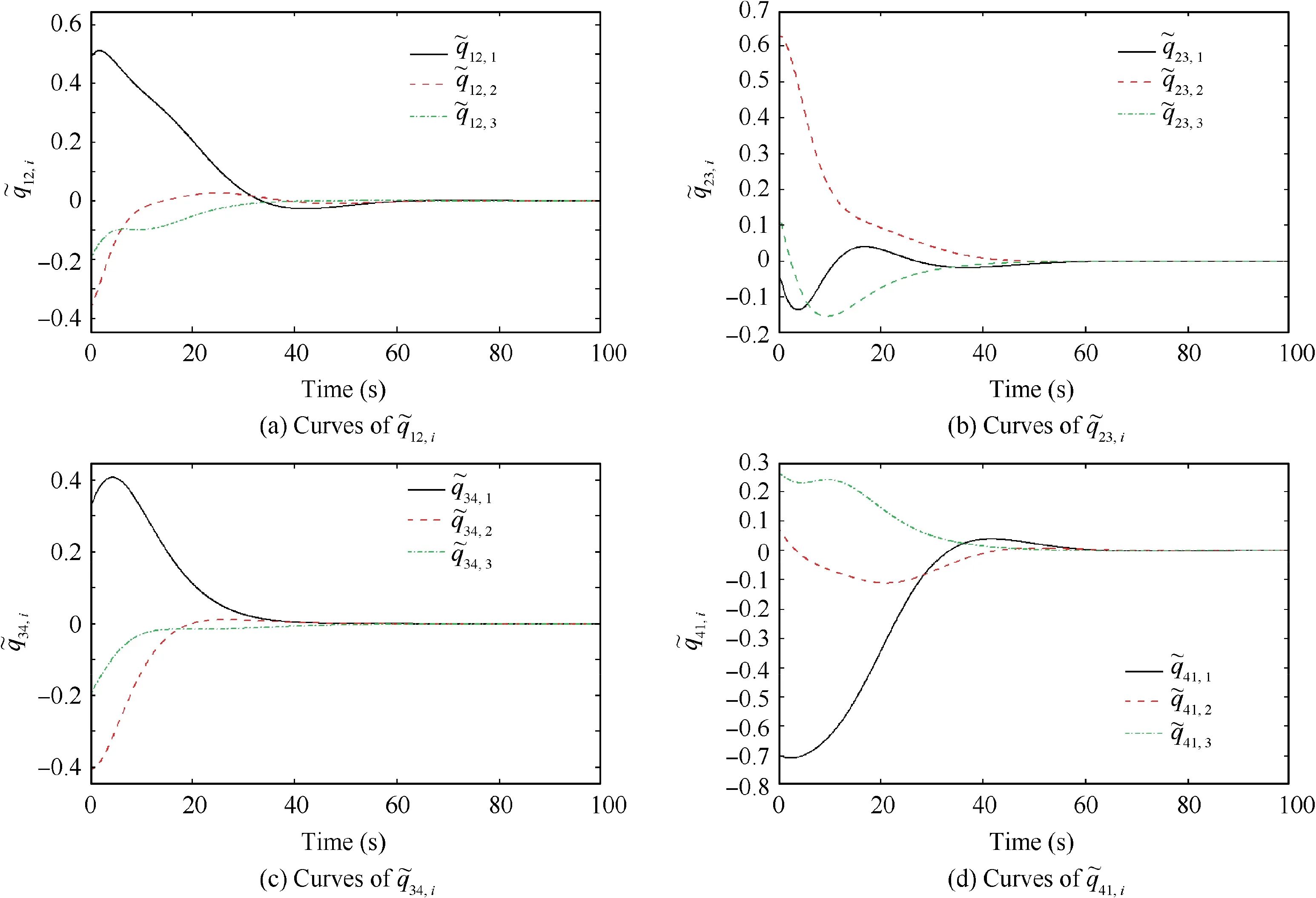
Fig. 8 Curves of q~12,i, q~23,i, q~34,i and q~41,i (v=5).
5. Conclusions
(1) The relative kinematic and dynamic equations of flexible spacecraft formation are given in this paper. Considering the effects of flexible mode, environmental disturbance and actuator installation deviation, we design the integral-type sliding mode surface and the corresponding integral sliding mode adaptive controller.Based on the directed communication topology of the nominal system of the spacecraft formation, we design a controller with and without communication delay, so that each spacecraft can stably track the expected attitude and keep the stability of the formation.
(2) The effectiveness of the proposed control laws is verified through practical simulation examples.
Acknowledgements
This work was supported by the National Natural Science Foundation of China (Nos. 61833009, 61690212 and 51875119) and the National Key Research and Development Project (No. 2016YFB0501203).
 CHINESE JOURNAL OF AERONAUTICS2021年3期
- CHINESE JOURNAL OF AERONAUTICS的其它文章
- Criteria for hypersonic airbreathing propulsion and its experimental verification
- Effect of scavenge port angles on flow distribution and performance of swirl-loop scavenging in 2-stroke aircraft diesel engine
- Ship detection and classification from optical remote sensing images: A survey
- Variational method based robust adaptive control for a guided spinning rocket
- Inertial parameter estimation and control of non-cooperative target with unilateral contact constraint
- Theoretical modeling of vectoring dual synthetic jet based on regression analysis
