Comprehensive optimization design of aerodynamic and electromagnetic scattering characteristics of serpentine nozzle
Yubo HE, Qingzhen YANG, Xiang GAO
School of Power and Energy, Northwestern Polytechnical University, Xi’an 710129, China
KEYWORDS Forward-Backward Iterative Physical Optics (FBIPO);Guarantee Convergence Particle Swarm Optimization(GCPSO);Nozzle design;Optimization design;Radar Cross Section (RCS);Serpentine nozzle
Abstract Comprehensive optimization design of serpentine nozzle with trapezoidal outlet was studied to improve its aerodynamic and electromagnetic scattering performance.Serpentine nozzles with different center offsets and different ratios of the bases of the trapezoidal outlet were generated based on curvature control regulation. Computational Fluid Dynamics (CFD) simulations have been conducted to obtain the flow field in the nozzle, and Forward-Backward Iterative Physical Optics (FBIPO) method was applied to study the electromagnetic scattering characteristics of the nozzle.Guarantee Convergence Particle Swarm Optimization(GCPSO)algorithm based on Radial Basis Function (RBF) neural network was used to optimize the geometry of the nozzle in consideration of its aerodynamic and electromagnetic scattering characteristics.The results show that the GCPSO method based on RBF can be used to optimize the aerodynamic characteristics of the internal flow and the scattering characteristics of the cavity of the serpentine nozzle with irregular outlet.The optimized model has a higher center offset and a lower ratio of the bases of the trapezoidal outlet after optimization compared to the original model. The optimized model leads to a slight change in aerodynamic performance, with a total pressure recovery coefficient increase of 0.31%and a discharge coefficient increase of 0.41%.In addition,the Radar Cross Section(RCS)decreases also by around 83.33%and the overall performance is significantly improved,with a decrease of the optimized objective function by around 38.74%.
1. Introduction
With the increasing threat of radar detection system,the radar stealth characteristics of military aircraft will meet new challenges. Nozzle as the main component of the engine exhaust system can be major contributors to total vehicle Radar Cross Section (RCS) due to its electrically large open-ended cavity properties, and its aerodynamic characteristics also have a great impact on the overall performance. For the sake of lowbackscatter profile of exhaust cavity, the nozzle can be designed as S-shaped to increase the number of reflections of the radar wave inside the cavity, thereby attenuating the scattering energy.In addition,the nozzle with 2D exits also shows lower backscatter signals compared to the conventional circular nozzle.Furthermore,exhaust nozzle with S-shaped and 2D exits exhibits a lower Infrared Radiation(IR)signature due to the shielding of high-temperature components and the reduction of detectable external jet length. Therefore, study on the aerodynamic and electromagnetic scattering characteristics of serpentine nozzle with 2D exit has become the main branches of the investigation of the stealth nozzle.
With the development of Computational Fluid Dynamics(CFD), the aerodynamic performance of serpentine nozzle has been studied extensively both experimentally and numerically in many literatures. Sun et al. did a lot of work on the internal flow characteristics and the impact of geometric parameters on the performance of serpentine nozzle by means of experimental and numerical simulations.1-3And response surface methodology was adopted to quickly estimate the aerodynamic performance of serpentine nozzle with different design parameters. Crowe and Martin Jr4-6studied the mechanism of the formation of hot streak in double serpentine nozzle and the impact of design parameters (i.e. aspect ratio,length-to-diameter ratio and swirl angle)on temperature distribution at exit. Finally, based on the numerical simulation results,the general design guidelines with varying nozzles were carried out.Reynolds et al.7,8investigated the flow field of interior of rectangular nozzle with opposite aspect ratios (2:1 and 1:2) and proved the secondary flow at the exit caused by two bends.Coates and Page9validated the accuracy of the numerical simulation methodology for rectangular S-bend nozzle and then studied the effect of upstream duct curvature on the performance of jet engine. The results show that the increase of upstream duct curvature indicates the reduction of potential core length of the duct and this will cause the additional momentum loss in the duct.
In terms of electromagnetic scattering characteristics of the nozzle, Burkholder and Lundin10proposed a Forward-Backward Iterative Physical Optics(FBIPO)algorithm for calculating the RCS of the open ended cavities. Based on this,Yang et al.11,12obtained the RCS characteristics of serpentine nozzle with varying exit through FBIPO.The results show that the difference in RCS values between different outlet shapes is large and serrated rectangular outlet could greatly reduce the backward RCS value of nozzle. Xiao et al.13investigated the effect of the aspect ratio of outlet on the electromagnetic characteristics of the nozzle,and it turns out that the RCS of the 2-D S-shaped nozzle with an aspect ratio of 5.5 has a smaller RCS in a large detection range. The application of Radar Absorbing Material(RAM)can also give significant reduction in signature with minimal effects on other performance of the targets.14Yang et al.15,16studied the effect of coating position on the reduction of RCS to obtain the most economical coating method.The numerical results show that RAM coating on the wall near the nozzle outlet could get a significant RCS reduction and economic benefits. In addition, the S-bended 2-D nozzle can greatly reduce the infrared radiation signature of the aircraft by shielding the high-temperature components.The research shows that the infrared radiation intensity of the trapezoidal outlet is significantly lower than that of the rectangular outlet and the elliptical outlet model, which can reduce the infrared radiation peak by at least 70% compared with the reference model.17
All these experimental and numerical investigations revealed the advantages of the serpentine nozzle.In this paper,Guarantee Convergence Particle Swarm Optimization(GCPSO) algorithm based on Radial Basis Function (RBF)neural network is used to optimize the aerodynamic characteristics and radar scattering characteristics of the serpentine nozzle with 2-D outlet.Subsequently,the numerical simulation of optimal model is carried out and the results are compared with those of the original model.
2. Optimization methodology
2.1. Guarantee convergence particle swarm optimization
Particle Swarm Optimization (PSO) is an optimization algorithm proposed by Kennedy and Eberhart18based on social behavior of the swarm. Its main principle is: each individual can be regarded as a free moving particle, and each particle updates its speed and position according to its own flying experience and its companions’flying experience.Subsequently,Shi and Eberhart19introduced a parameter inertia weight ω in the speed update process to balance local search ability and global search ability,which is considered as standard PSO in the further study. Thus, the standard PSO algorithm is defined as
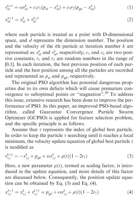
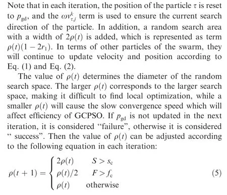
where S and F represent the number of consecutive successes and failures, respectively; scand fcare threshold parameters,and their values are selected according to the complexity of the objective function. Based on Bergh and Engelbrecht’s research,21sc= 15, fc= 5 will be set in this paper, which means that the algorithm will punish the poor ρ faster.In addition, the initial value of ρ is set to 1.
In order to verify the superiority of the improved algorithm introduced above, a testing function f is adopted to compare the performance of standard PSO and GCPSO.The definition of f is shown in Eq.(6),and the corresponding function graph is depicted in Fig. 1.

For comparison,both algorithms deploy the same parameter settings:The size of the swarm is 20;the maximum number of iterations allowed is 1000;a time varying inertia weight ω is adopted, and it starts with a larger value of 0.9 and drops linearly to 0.4 when the number of iterations reaches 1000. Each algorithm is tested 200 times and the results are shown in Table 1.
It can be concluded from Table 1 that GCPSO has better performance compared with standard PSO, so it can be used for the optimization of different objective functions in the following study.
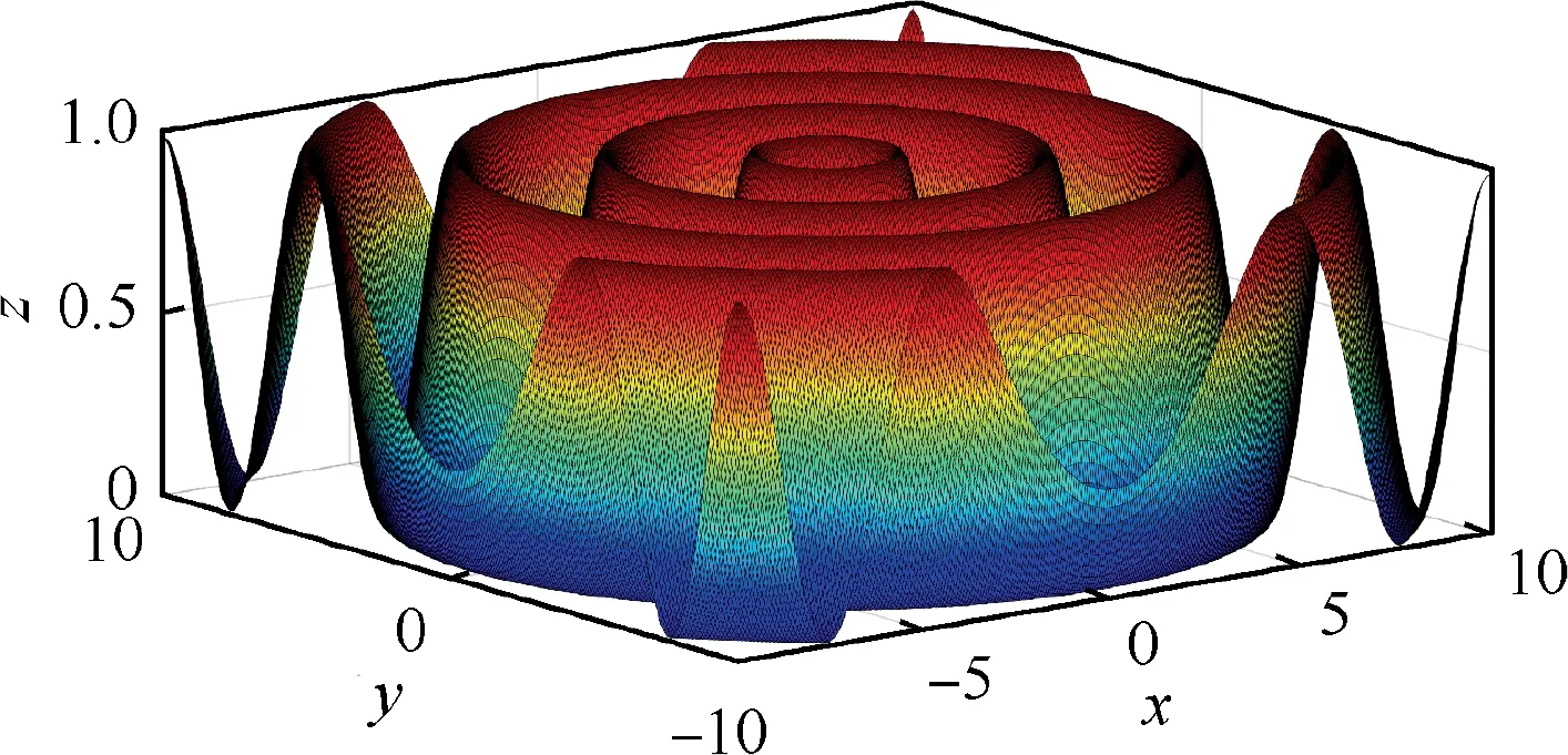
Fig. 1 Function image.
2.2. Radial basis function
In the actual optimization process,the specific expression form of the optimization object is not clear, so it is necessary to model the optimization object through fewer samples. Radial Basis Function (RBF) network has been widely used in modelling non-linear systems for its better approximation, simpler network architecture and faster learning algorithm. The RBF network consists of an input layer,a hidden layer,and an output layer, and the performance of RBF network mainly depends on the number of neurons in the hidden layer,the centers and the widths of the basis functions. In the training process of the RBF network,the number of neurons in the hidden layer is generally set between the sample dimension and the total number of samples, and the center vector and widths of the basis function are generally obtained by the training method.
In order to obtain simple and accurate RBF network,GCPSO algorithm is adopted to optimize the number of neurons of hidden layer and to obtain the optimal center vectors and the widths of the basis function in this paper.For detailed optimization process, please refer to Ref. 22
3. Geometry and computational methods
3.1. Geometry
The serpentine nozzle studied throughout this study has a trapezoidal outlet, and a cross-sectional shape generating method based on curvature regulation is used to control the shape of the middle cross section of the serpentine nozzle.The modest strategy is adopted for the centerline and area change laws, as defined

where y and A represent the center offset and area of cross section at position x;Δy is the center offset of pipe inlet and outlet;L is the total length of the pipeline;A1and A2are the inlet and outlet area of the pipeline.For details,please refer to Ref.23
The definition of inlet parameters and values are given in Fig. 2 and Table 2, respectively.
3.2. Computational methods
3.2.1. Aerodynamic
The entire computational domain is discretized using structured mesh, and the grids are clustered close to the inlet wall to make sure the boundary layer grids have a y+ near 1.Three-dimensional numerical simulations are carried out, and 3D, steady, Reynolds-average Navier-Stokes equations are selected as the governing equations. Second-order centraldifference scheme is adopted for the spatial discretization.Two-equation shear stress transport model is used for all the simulation in this paper.

Table 1 Calculation results of different algorithms.
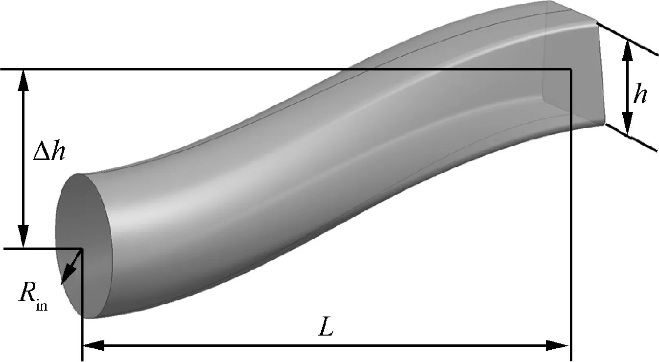
Fig. 2 Nozzle geometry.
The boundary conditions of the computational domain are defined as follows: no-slip, adiabatic wall boundaries are imposed on the serpentine nozzle wall.The ambient region surrounding the serpentine nozzle is defined as the pressure far field. The exit of the nozzle is defined as interior condition,and the total pressure and total temperature boundary condition is applied to the entrance of nozzle. The simulation is throughout conducted at flight altitude of 11 km and speed of Ma=0.6.Specific parameter settings are shown in Table 3.
In order to verify the accuracy of the simulation results, a thrust-vectoring axisymmetric nozzle of NASA is selected for numerical simulation, and its geometric structure is presented in Fig. 3. The nozzle pressure ratio is 3.5, and the geometric pitch angle γ=10°is applied. Fig.4 shows the static pressure distribution on the upper and lower wall of the vector nozzle respectively. The ratio of wall horizontal coordinates to L2is used as the abscissa, and the ratio of wall static pressure p to total pressure P0is used as ordinate. As can be clearly seen,the calculated results are basically consistent with the experimental results at the measurement points, and show the same changing trend. Therefore, the numerical simulation method adopted can better simulate the transonic flow and separation flow in the three-dimensional flow field of the nozzle, and it is suitable for the performance analysis of the serpentine nozzle studied in this paper.
3.2.2. Electromagnetic
Iterative Physical Optics (IPO) was developed to obtain the electromagnetic characteristics of electrically large open-ended cavities, such as aircraft inlets and nozzles. As a highfrequency asymptotic method, IPO has higher efficiency than purely numerical methods such as the method of moments and finite element method, and a much coarser discretization density is needed for the simulation. In this paper, in order to improve convergence speed and accuracy, forward-backward propagation methodology is combined with the conventional IPO, and a relaxation parameter is also introduced to improve convergence efficiency.On the other hand,the Equivalent Edge Current (EEC) method is also adopted to include diffraction effects at the edges.24

Table 2 Values of serpentine nozzle (unit: mm).

Table 3 Boundary conditions.
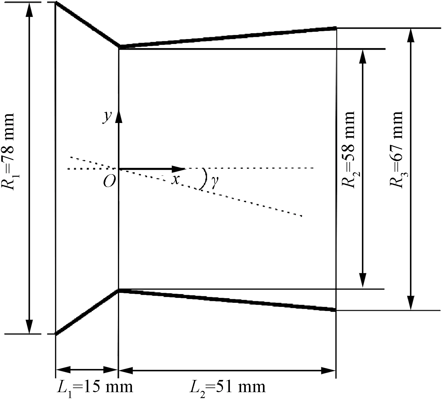
Fig. 3 Flow path of NASA vectoring nozzle.
In order to validate the reliability of the methodology described above, FBIPO and FBIPO+EEC are applied to obtain electromagnetic scattering characteristics of large open-ended cavities25and trihedral corner reflectors26respectively. The specific geometric structure and parameter settings are shown in Fig.5,where λ is the incident wave length.Fig.6 shows the RCS distribution of open-ended cavities and trihedral corner reflectors in the horizontal polarization, and the ordinate is the radar scattering cross section, which can be obtained by Eq. (9). It is observed that the simulation results are in good agreement with the references and experiment results. Therefore, the numerical simulation method adopted in this paper has high reliability.

3.3. Optimization function

Fig. 4 Static pressure distribution on vectoring nozzle.
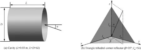
Fig. 5 Geometry of cavity and triangle trihedral corner reflector.

Fig. 6 RCS distribution of each model.
The comprehensive optimization design of the aerodynamic and electromagnetic scattering characteristics of serpentine nozzle involves multi-disciplinary and multi-objective optimization problems.The traditional methods for such problems include coefficient weighting method, pareto optimal solution,ε-constraint method and Multidisciplinary Design Optimization (MDO). The coefficient weighting method integrates the objective function into a single objective function by the way of weighted sum, which is easy to understand and to implement with the program.27,28The pareto method is to obtain a set of non-dominated solutions,called pareto front,through optimization algorithms.29,30Among these solutions,no objective can be improved without sacrificing at least one other objective, and engineers can choose the appropriate solution from Pareto front according to the practical needs. εconstraint method is to keep only one objective function,and set other objective functions as constraints of the optimization problem.31,32MDO is an optimized design method,which analyzes the interaction of different disciplines in the design process of complex systems and makes full use of these interaction to optimize the system.33,34However, disciplinary models are often complex and time-consuming, and their convergence cannot be guaranteed.35In this paper, due to the large number of objective functions and the complex interaction between them, the objective functions of different disciplines are normalized and weighted into a single objective function by the coefficient weighting method.
3.3.1. Aerodynamic optimizing objective function
As the main flow characteristics of the nozzle, the flow discharge coefficient CDand the total pressure recovery coefficient σerepresent the flow capacity of the nozzle and the total pressure loss in the pipeline,respectively.Therefore,a fitness function called aerodynamic optimizing objective function is defined as

where f1is aerodynamic optimizing objective function, and α1and α2represent the weights of CDand σerespectively. In this paper, α1and α2are both set to a value of 0.5.
3.3.2. Electromagnetic optimizing objective function
The electromagnetic optimizing objective function is a linear combination of RCS mean values at different detection angles and different polarization characters, as defined in Eq. (11),and the smaller the function value, the better the electromagnetic stealth performance of the nozzle.

where σθpand σθhrepresent the average RCS in the pitch plane and the yaw plane under the horizontal polarization, respectively,and σφpand σφhrepresent the average RCS in the pitch plane and the yaw plane under the vertical polarization,respectively. β1, β2, β3and β4are the weights corresponding to the average RCS noted above, as seen in Eq. (11). It is to be noted here that the unit of RCS is square meter (m2).
When the flight altitude is 11 km,and the attacked fighter is above or below the attack aircraft no more than 1 km, the radar exposure can be viewed as plane exposure, so β2is set to 0.6. Considering that the horizontal polarization is still the main way for fighters to be detected at the same altitude,so β1is set to 0.2, and β3and β4are set to 0.1. In addition,for long-range fighters, due to the large detection range of its airborne radar,36the distance between target aircraft and the attack aircraft is much greater than its distance in the vertical or yaw direction, that is D ≫ΔD. Therefore, the radar incidence angle of the target aircraft is generally not too large,as shown in Fig. 7. In this paper, both the elevation angle θ and the yaw detection angle φ are limited to the range from-30° to 30°.
3.3.3. Comprehensive optimization objective function
In practical nozzle design, not only aerodynamic performance but also radar stealth characteristics should be considered.Therefore, aerodynamic performance and electromagnetic stealth characteristics of the nozzle will be comprehensively considered in this paper, and its objective function ftotalis defined as

where f1and fradarare the aerodynamic optimization objective function and the electromagnetic optimization objective function defined above, respectively, and N1f1and N2fradarrepresent the normalization processing of f1and fradar,respectively. It should be noted here that the small value of fradarrepresents good radar stealth performance, while the large value of f1corresponds to good aerodynamic performance. Therefore, 1-N1f1is processed, so that the smaller the ftotal, the better the overall performance of the nozzle.For weight coefficients ω1and ω2,aerodynamic characteristics will be taken into prior consideration in this paper, so ω1= 0.7 and ω2= 0.3 are applied.
In this paper,the center offset Δh and the ratio of the trapezoidal bases b are optimized while total length L of the nozzle and the trapezoidal height h of the outlet remain unchanged,and the descriptor ftotaldefined above is selected as the fitness function. For the practical application, Δh is clamped to the range from 500 mm to 900 mm, and b is limited to the range[0,1]. Therefore, the optimization problem in this paper can be described as
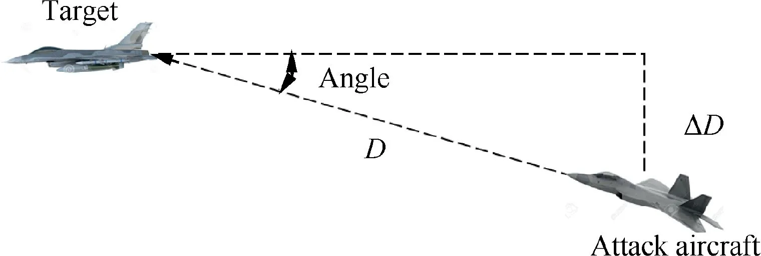
Fig. 7 Schematic diagram of relative position of attack aircraft and target.

4. Results and discussion
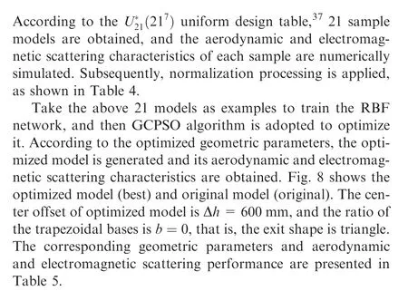
As summarized in Table 5,the center offset Δh of the model after optimization is increased by about 60 mm, and the exit shape is closer to a triangle. Due to the S-bend structure of the nozzle, there is a limitation to its aerodynamic improvement and marginal improvement in total pressure ratio and flow discharge coefficient is achieved by a maximum of 0.31% and 0.41% respectively. In terms of electromagnetic performance of serpentine nozzle after optimization, the RCS is significantly reduced under different detection methods, with a maximum reduction of 90.39%, and the electro-magnetic stealth performance of the optimized model has been improved with fradarreduced by about 83.33%. Consequently,compared with the original model, the comprehensive performance of the optimized model is improved, and the fitness function ftotalis reduced by about 38.74%.
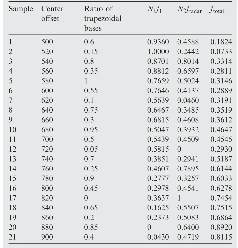
Table 4 Result of samples.
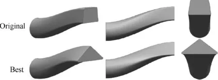
Fig. 8 Geometry of original model and comprehensive optimal model.
In order to highlight the superiority of the optimal model,the aerodynamic and electromagnetic characteristics of the optimal model, the original model and the sample-1, sample-21 models in Table 4 are performed.Fig.9 illustrates the static pressure distribution at the symmetry plane of each model.It is observed that each nozzle shows a similar static pressure distribution, and a significant high-pressure region and a lowpressure region occurred near the lower wall and upper wall respectively, which can be attributed to the curvature of the serpentine nozzle. As flow develops, the static pressure distribution tends to be relatively uniform at the middle section of the nozzle. Subsequently, the low-pressure region is mainly concentrated near the lower wall at the nozzle exit due to the deflection of the airflow in the opposite direction. Compared with sample-21,the optimized model has a more uniform static pressure distribution near the entrance and exit.This is mainly because the optimized model has a smaller center offset,so the non-uniformity of pressure distribution caused by the deflection of the airflow is smaller.In addition,compared with other models, the low-pressure region near the upper wall of the entrance of the optimized model is relatively smaller, and it also shows a more uniform pressure distribution in the jet region.
Shown in Fig. 10 are static pressure distribution of the upper and lower walls on the symmetry plane of each model,where the distance to the nozzle entrance is used as the abscissa. According to Fig. 10(a), there is no obvious difference among the optimized model, sample-1 and sample-21 at the range of 0-0.6 m, and then the static pressure graduallydecreases, but the original model and sample-1 show a faster pressure decay compared to the optimized model, which can be attributed to the similar exit of original model and sample-1.The acute change of airflow direction at the entrance of sample-21 results in a smaller value of the low-pressure region,and then the static pressure gradually increases, reaching the maximum value near 0.75 m. Finally, the static pressure drops sharply at the nozzle exit due to boundary conditions.In terms of pressure distribution at the lower wall,as depicted in Fig. 10(b), the difference between these models can be negligible, and all of them gradually decrease as flow develops, with only slight differences near the nozzle exit.
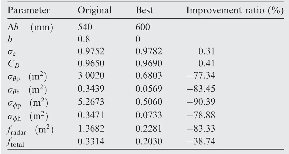
Table 5 Comparison between two models.
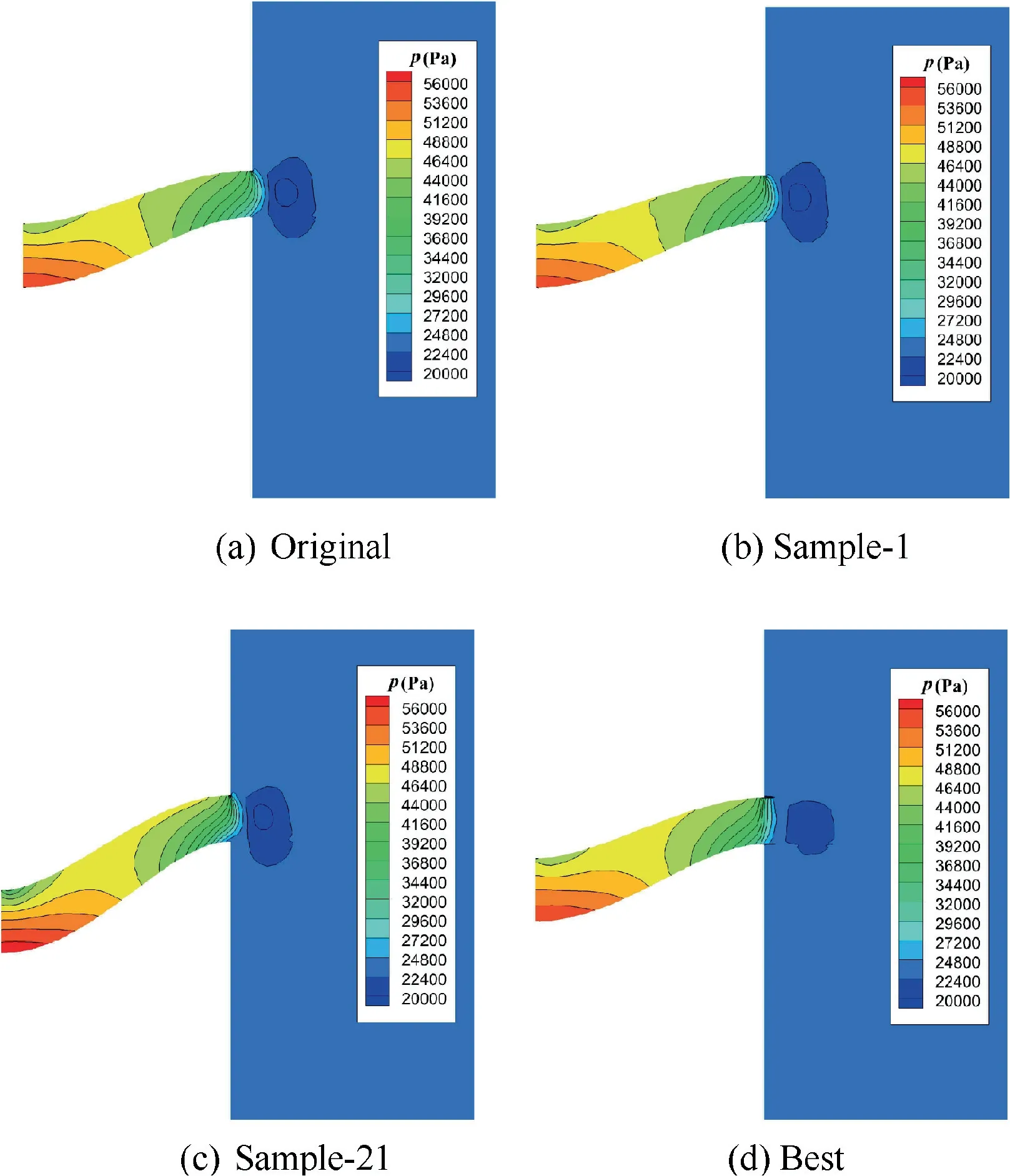
Fig. 9 Static pressure contour at symmetrical plane.
Fig. 11 is included to clarify the distribution of Mach contours in cross section of each model.As can be clearly seen,the velocity profiles show large non-uniformity at plane a and plane b, at that time, low speed region is mainly distributed at the base of the nozzle,and as flow develops,its extent gradually decreases and becomes more evenly distributed at plane c. Due to the wall curvature and transition, the high-velocity region appears near the lower wall, and the Mach number reaches the maximum at plane e. It is worth noting that the non-uniformity of the Mach number distribution at the exit of the model after optimization is significantly reduced, and the intensity and extent of high-Mach region and low-Mach region on the upper and lower walls are effectively reduced.Therefore, from these results, preliminary conclusions can be drawn that more uniform distribution can be obtained after optimization, and aerodynamic performance of serpentine nozzle is improved in terms of total pressure recovery and flow discharge coefficient.

Fig. 10 Static pressure distribution.
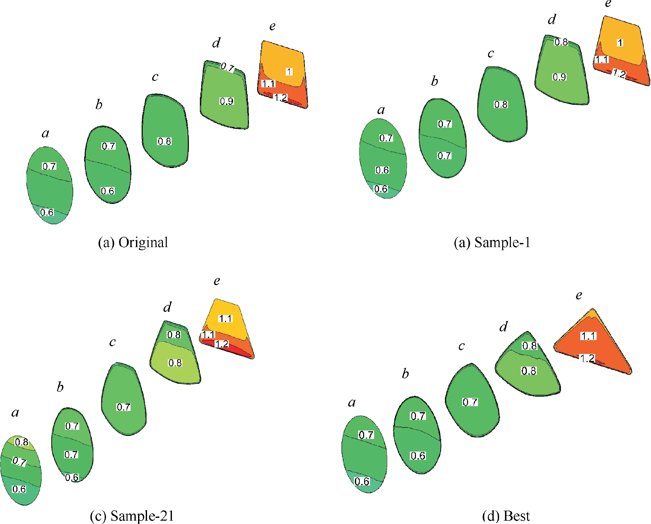
Fig. 11 Mach number contour at flow field section.

Fig. 12 RCS of different models at pitch detection plane.
Fig. 12 shows the comparison of RCS distribution of each model in the pitch detection plane under different polarization,where the elevation angle θ is used as the abscissa. As can be seen, the general shape of RCS is similar under horizontal polarization and vertical polarization, so only the RCS distribution under horizontal polarization is analyzed in detail. As depicted in Fig. 12(a), the S-curved structure of each model leads to the asymmetry distribution of RCS about 0°detection angle. The original model, sample-1 and sample-21 have the similar RCS distributions,that is,the peak of RCSs occur near the incident angle of-22°,0°and 28°,reach a maximum when viewed at the back (θ=0°), and drop to -28 dBsm around θ=10°. For the optimized model, we can observe a broad RCS reduction under upward view (θ<0°), with the values all below-10 dBsm. When the incident angle θ>0°, as the angle increases, the area of nozzle that can be directly irradiated increases, resulting in the increase of RCS of optimized model, and the RCS reaches its maximum at θ=28° which is still smaller than that of original model and sample-1.Through comparison, it is found that the RCS value of the optimized model is less than that of original model and sample-1 over most observation angles, while model-21 has a relatively small RCS value at 20°-30°due to its large center offset and high shield ratio.As summarized in Table 5,compared with the original model, the average RCS of the optimized model under horizontal and vertical polarization in the pitch detection plane decrease by about 77.34% and 90.39%,respectively.
Fig. 13 shows the induced current distribution counters of each model at elevation angle θ=-25° and θ=25° under horizontal polarization. As seen in Fig. 13(a), at a elevation angle of θ=-25°,the electromagnetic wave is directly irradiated to the upper wall of the nozzle exit,resulting in a medium intensity induced current on the upper wall. Then the electromagnetic wave enters the nozzle through multiple bounces,and a high intensity induced current occurs at the bottom of entrance face of the original model, sample-1 and sample-21,accompanied by medium intensity induced current at the center of entrance plane. By contrast, the induced current of the optimized model is evenly distributed on the wall and the value is at a lower level.
At the incident angle of θ=25°,the wall of serpentine nozzle that can be directly detected by electromagnetic waves increases, which will lead to the generation of high intensity induced current. As depicted in Fig. 13(b), both the intensity and the extent of induced current of original and sample-1 increase significantly, which will result in strong backscatter,and the optimization model also produces a medium intensity induced current at the nozzle entrance,but its magnitude is still less than that of the original model and sample-1. Note that the intensity of induced current of model-21 diminishes compared to other models, and this can be mainly attributed to its large center offset, which can effectively increase the number of bounces of electromagnetic wave inside the nozzle and each bounce can attenuate the signal energy. Consequently,sample-21 has a relatively low RCS, which is consistent with RCS distribution depicted in Fig. 12(a).
The comparison of RCS distribution of each model in the yaw detection plane under different polarization is presented in Fig. 14 and only the RCS characteristics under horizontal polarization are presented due to their similar distribution. It can be seen from Fig. 14(a) that the RCS distribution is symmetrical about 0°detection angle due to the left-right symmetrical structure of the serpentine nozzle. The original model,sample-1 and sample-21 have basically similar RCS distribution, and only show a minor peak value difference at the 0°detection angle. Then, as the detection angle increases, the electromagnetic energy entering the nozzle decreases, so the overall RCS presents the downward trend.After optimization,the RCS reaches the maximum at the detection angle of 0°,and its signature has dropped to a low level at a range of 0°-6°compared to the other models.Although the RCS of the optimized model is larger than that of the other three models at the detection angle of 8°-18°,RCSs are all below 0 dBsm,and thus the contribution to the average RCS value is negligible.Therefore,as shown in Table 5,the average RCS of the optimized model under horizontal and vertical polarization at the yaw detection plane decrease by about 83.45% and 78.88%, respectively.
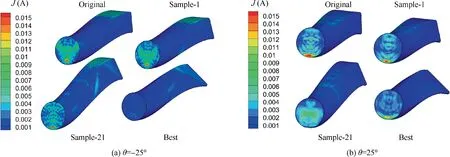
Fig. 13 Induced current distribution at pitch detection plane.

Fig. 14 RCS of different models at yaw detection plane.
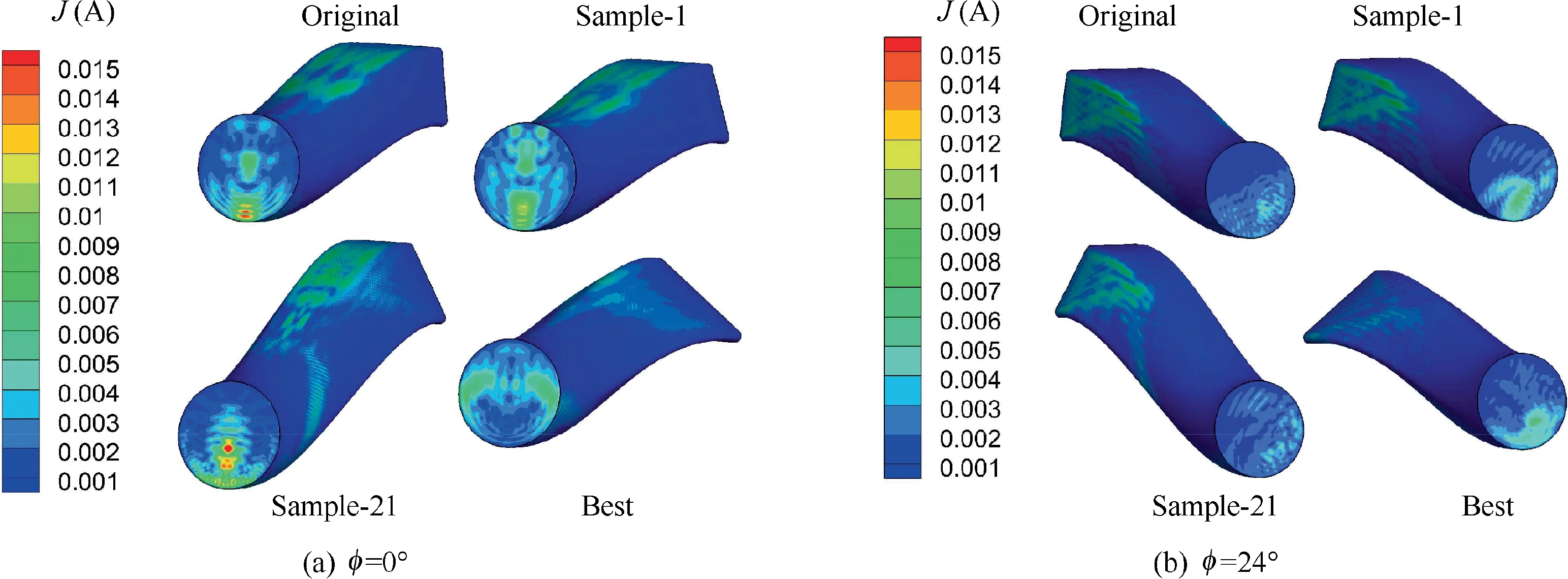
Fig. 15 Induced current distribution at yaw detection plane.
Fig. 15 shows the induced current contours of each model at yaw detection angle 0° and 24° under horizontal polarization. It can be seen that the nozzles generate induced current with medium intensity at the area directly irradiated by electromagnetic waves.When the incident angle is 0°,the electromagnetic wave forms a high intensity induced current on the nozzle entrance surface after multiple reflections, such as sample-21.However,the optimized model does not generate a high intensity induced current at the bottom of the entrance, and only a medium intensity induced current appears on both sides,which corresponds to a weak backscatter. As the incident angle is increased to 24°,a significant reduction in the induced current intensity has been accomplished, as shown in Fig. 15(b), and no obvious high intensity induced current region has appeared,which reveals the influence of the incident angle on the backscatter intensity. Furthermore, the distribution of each model is basically similar, with minor discrepancies in the extent of medium intensity induced current.
5. Conclusions
The purpose of this paper is to comprehensively optimize the aerodynamic and electromagnetic characteristics of the serpentine nozzle through GCPSO algorithm based on RBF. Comparison of the characteristics of the optimized model with the original model and the sample models is made. The main conclusions can be drawn as follows:
(1) The GCPSO algorithm based on RBF can accurately model and optimize the non-linear systems with a small number of samples. Compared with the conventional PSO algorithm, GCPSO shows attractive advantages of high convergence accuracy and high efficiency,which can be used in optimum design of nozzle in this paper.
(2) After optimization, a more uniform Mach and pressure distribution near the exit of serpentine nozzle and jet area are obtained. Marginal improvement of aerodynamic performance is achieved, that is, total pressure recovery and discharge coefficient increase by 0.31%and 0.41%, respectively.
(3) In terms of electromagnetic performance,an appreciable reduction in average RCS under different polarization modes is achieved after optimization, with the highest decrease reaching 90.39%. The comprehensive properties of the serpentine nozzle are improved, and the fitness function ftotalis reduced by 38.74%.
(4) The comprehensive optimization method developed in this paper can effectively optimize the nozzle of the aircraft engine and provide reliable technical guidance for the design of the nozzle in the further study.
Declaration of Competing Interest
The authors declare that they have no known competing financial interests or personal relationships that could have appeared to influence the work reported in this paper.
Acknowledgement
The authors would like to express their gratitude for the financial support of the Fundamental Research Funds for the Central Universities (No. 31020190MS708).
 CHINESE JOURNAL OF AERONAUTICS2021年3期
- CHINESE JOURNAL OF AERONAUTICS的其它文章
- Criteria for hypersonic airbreathing propulsion and its experimental verification
- Effect of scavenge port angles on flow distribution and performance of swirl-loop scavenging in 2-stroke aircraft diesel engine
- Ship detection and classification from optical remote sensing images: A survey
- Variational method based robust adaptive control for a guided spinning rocket
- Inertial parameter estimation and control of non-cooperative target with unilateral contact constraint
- Theoretical modeling of vectoring dual synthetic jet based on regression analysis
