Mathematical modeling of an armature assembly in pilot stage of a hydraulic servo valve based on distributed parameters
Xinbei LV, Jinghui PENG, Songjing LI
Department of Fluid Control and Automation, Harbin Institute of Technology, Harbin 150001, China
KEYWORDS Armature assembly;Distributed parameters method;Dynamics;Mathematical models;Servo valve
Abstract The dynamic performance of a nozzle-flapper servo valve can be affected by several factors such as the disturbance of the input signal,the motion of the armature assembly and the oscillation of the jet force.As the part of vibrating at high frequency,the armature assembly plays a vital role during the operation of the servo valve.In order to accurately predict the transient response of the armature assembly during the vibration, a mathematical model of armature assembly is established based on the distributed parameters method(DPM)and Hamilton principle.The new mathematical model is composed of three main parts, the modal eigenfunction, modal mechanical response expressions of the spring tube and the motion equation of the other armature assembly.After programing,the purpose of using the DPM to predict the dynamic response of different positions located on the armature assembly is achieved. For verifying the validity of the mathematical model, the finite element method (FEM) and classic model (CM) of armature assembly are applicated by commercial software under the same condition. The comparison results prove that the DPM can effectively predict the axial and tangential deflection of the armature assembly different positions which the CM can’t duing to its over-simplification.A certain error is generated when predicting the axial deformation at different heights by DPM, which is caused by an approximate method to simulate the torsion of the spring tube.The comparison results of the spring tube deflection at different vibration frequencies shows that the adaptability of DPM is significantly higher than the classic model, which verify the model is more adaptable for predicting the dynamic response of the armature assembly.
1. Introduction
Electro-hydraulic servo valve has been widely used in many industrial fields for more than half a century. As one of the critical components in the hydraulic control system, the electro-hydraulic servo valve plays a vital role which converts the electrical signal to the force signal.According to the special structure of the pilot stage and high-frequency working conditions,the self-oscillation is frequently induced during the operation of the electro-hydraulic servo valve, which is an important factor limiting its wider application and eventually rupturing the spring tube. The performance of the armature assembly usually determines the stability of the servo valve and even the entire hydraulic system. Thus, as one of the important methods to predict structural deformation, the dynamic mathematical model for investigating the mechanism of armature assembly vibrating is in urgent need.
For avoiding the self-excited oscillation of the servo valve,some researchers have already got some achievements.1-4Chen et al.5observed the nonlinear propagation characteristics of pressure pulsation in the pipeline and the pulsation characteristics of the flow field under different conditions by combining CFD simulation and experiments. For suppressing the vibration and pressure pulsation of the servo valve, a pulsation damper at the nozzle inlet was designed and verified by the numerical simulation. Wu et al.6,7used the large-eddy simulation to observe the dynamic characteristics of the cavitation in the pilot stage of servo valve. With this numerical simulation model, the unsteady flow field with a rectangular nozzle was simulated and the optimal nozzle size was obtained. Bertin et al.8designed a novel piezoelectric nozzle-flapper servo valve whose pilot stage was actuated by a piezoelectric ring bender of dual lane instead of the torque motor.This new servo valve improved the service life while eliminating the failures associated with the fine wire devices,which was proved by numerical simulation and experiment.Lee et al.9presented a feedforward controller for a three-stage servo-valve. the validity of the closed-loop injection architecture was verified which could minimize the analytical time consuming for the parameter identification of the three-stage servo-valve. Most of these researchers focus on the performance improvement of the servo valve by numerical simulation and experiments and the lack of the theoretical guidance make it impossible to explain the principle of self-excited oscillation.
The mathematical modeling for servo valves which can predict its performance has been the research focus since the birth of the servo valves.Arafa and Rizk10investigated the deformation of the feedback rod caused by the electromagnetic force,and an accurate nonlinear mathematical model of the electro-hydraulic servo valve which could be a new criterion for quality and performance of electrohydraulic servo-valves was established. Ferreira et al.11proposed a new model for the electro-hydraulic proportional valve which called the semi-empirical model. On the basic of the experimental data,the static and dynamic parameters was calculated by the model, and the spool dynamics were also modelled by a nonlinear second-order system with limited velocity and acceleration. Li and Song12presented a dynamic mathematical model for the torque motor and magnetic fluids of a hydraulic servovalve. The dynamic response of the torque motor affected by magnetic fluids were simulated and tested by the experiment data. Somashekhar et al.13derived a mathematical model of a jet pipe servo valve system by FEM, and the accuracy of the mathematical model was verified by the experiment and numerical simulation. Dasgupta and Murrenhoff14used the method of power bond diagram to establish a dynamic mathematical model of the valve-controlled hydraulic motor based on the nonlinear model of the servo valve established by previous researchers. Mu and Li15,16derived a transfer function which contains the components of the electro-hydraulic servo valve pilot stage,the main spool and so on.With the nonlinear state space description of the nozzle-flapper electro-hydraulic servo valve, the mathematical model for numerical simulation was obtained,which provided a theoretical basis for analyzing the solid-state vibration phenomenon and the vibration control of the electro-hydraulic servo valves. Liu and Jiang17investigated a seventh-order mathematical model to predict the physical behavior of a servo valve, and the linear control design approach using the new model had higher accuracy comparing with using classical mode. Wang and Lin18developed a dynamic model to describe the performance of jet pipe servo valve under random vibration environment.Meanwhile,the Monte Carlo method was proposed to simulate the reliability of the servo valve with the help of mathematical model,and the standard-deviation reliability of the entire system were improved. Bijan et al.19established the mathematical model of the flow field distribution in the pilot stage of the deflection flapper servo-valve by using the incompressible Schlichting velocity equation, which were verified by comparison with the experimental results. In the process of modeling the mathematical model of the servo valve, the centralized parametric mathematical model is the mainstream research method, it focuses on the performance prediction of the servo valve which also makes a shortage of transient motion explanation, that makes it impossible to theoretically ameliorate the selfexcited oscillation of a servo valve.
In the process of establishing the transient mathematical model for the unit whose structure is the similar to the armature assembly, the DPM has become one of the most important methods. Shi et al.20established a distributed mathematical model for a doubly clamped beam to determine the its stress-strain curve which was confirmed by the experiment data. The model was based on that, the deformation in the doubly clamped beam was dominated by the axial stretching much larger.Erturk and Inman21proposed the DPM with the closed-form analytical solution for a cantilever based on the assumptions of Euler-Bernoulli beam. This model was applied to bimorph cantilever configuration which could successfully predict its coupled system dynamics. Wang et al.22established a microscale distributed parameter beam model based on the Hamilton’s principle and the strain gradient elasticity theory. If the shear deformation was ignored, the model could be restored to the traditional Bernoulli-Euler beam model.Ma and Chen23presented a new method for modelling the flexible beam of large deflections called the chained beamconstraint model. Some examples were implemented to verify that the new model could efficiently predict the large deflection problems of compliant mechanisms. Ling et al.24analyzed the dynamic response of a compliant mechanisms based on D’alembert’s principle and on the pseudo-static model. Comparing with literature data and FEM results, the accuracy and simplicity of this method is demonstrated. Li et al.25provided a new semi analytical DPM to analyze the free vibration of cylindrical shell. The model was established on the basis of energy method and the accuracy of the mathematical model were verified by FEM. Xie et al.26developed a distributed parameters model for the dynamic response of the drillstring in a horizontal well having six Degrees-Of-Freedom,which contained the longitudinal, lateral and torsional motions. The model was tested by the experiments as the friction and cutting effects were considered and the robust of the model was verified. As can be seen, the distributed parameter model is one of the important methods to study the transient vibration of structures. Therefore, modeling the armature assembly of servo valves based on the distributed parameters has become one of the feasible methods to observe the dynamic performance of servo valves.
Thus, in order to explore the dynamic performance of armature assembly and achieve the further purpose of eliminating self-excited vibration,the idea of this work is establishing the distributed parameters mathematical model of armature assembly.
2. Working principle of servo-valve
The nozzle-flapper servo valve is famous for its advantage of high-speed responsibility and output pressure. The typical structure of nozzle-flapper pilot stage is shown in Fig.1,which consists of three major parts including the torque motor,pilot stage and main spool.The electrical input signal is transmitted by the torque motor and converted into the electromagnetic force and drives the armature assembly to rotate.The rotation leads to the pressure difference of the symmetrical nozzle,which subsequently transmits to the main spool along the channel between the nozzle and the main spool.When the torque generated by the deformation of the feedback rod and the spring tube is balanced with the electromagnetic torque, the armature assembly is in a balanced position. When the end of the feedback rod is further deformed as the main spool moves, the offset of the flapper decreases, which causes the reduction of the pressure difference between the both sides of the flapper and main spool. When the pressure difference acting on the main spool balances with the reaction force generated by the feedback rod deformation, the spool stops moving. The classical mathematical model27of the armature assembly motion is a lumped parametric mathematical model which includes the electromagnetic torque,jet torque,feedback torque and the motion parameters of armature assembly.This model regards the spring tube as a single-span beam by considering the dynamics as a stiffness term. The rotation angle of the armature assembly is the only factor considered, and the factors such as translation and deformation are ignored. In the process of structural vibration dynamic analysis, an oversimplified model will lose most of the structural dynamic characteristics.
3. Distributed parameters mathematical model of armature assembly
Compared with the flapper and the feedback rod, the spring tube has a lower stiffness and inertia moment by which it plays a major role in the process of the vibration. Therefore, the parts of armature assembly except the spring tube can be regarded as rigid bodies in the mathematical modelling process.
The external load of the armature assembly in the pilot stage is mainly divided into three types,the jet force generated by the nozzle jet, the electromagnetic force generated by the torque motor and the feedback force transmitted by the main spool as shown in Fig. 2(a). As the first step in establishing a mathematical model, this article focuses on the dynamic response of armature assembly impacted by the driving forces of electromagnetic, and the influence of remaining forces is ignored.
The spring tube is regarded as a cantilever beam whose one end is fixed and the other one is a free end with additional mass and inertia moment belonging to the flapper and feedback rod as shown in Fig. 2(b). The assumption of the Euler beam is used for modelling the spring tube deformation, which only calculates the tangential shear deformation of the beam and ignores the axial shear deformation. The flapper rotation ignored is approximate by the product of the empirical constant and the bending angle at the spring tube top as plotted in Fig.2(b).The centre of the armature rotation is assumed to be the midpoint of the interface between the armature and the spring tube.
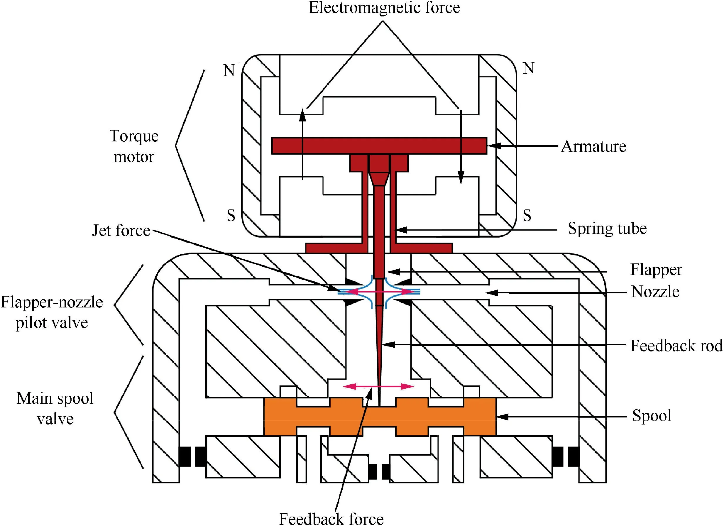
Fig. 1 Structure of numerical simulation model.
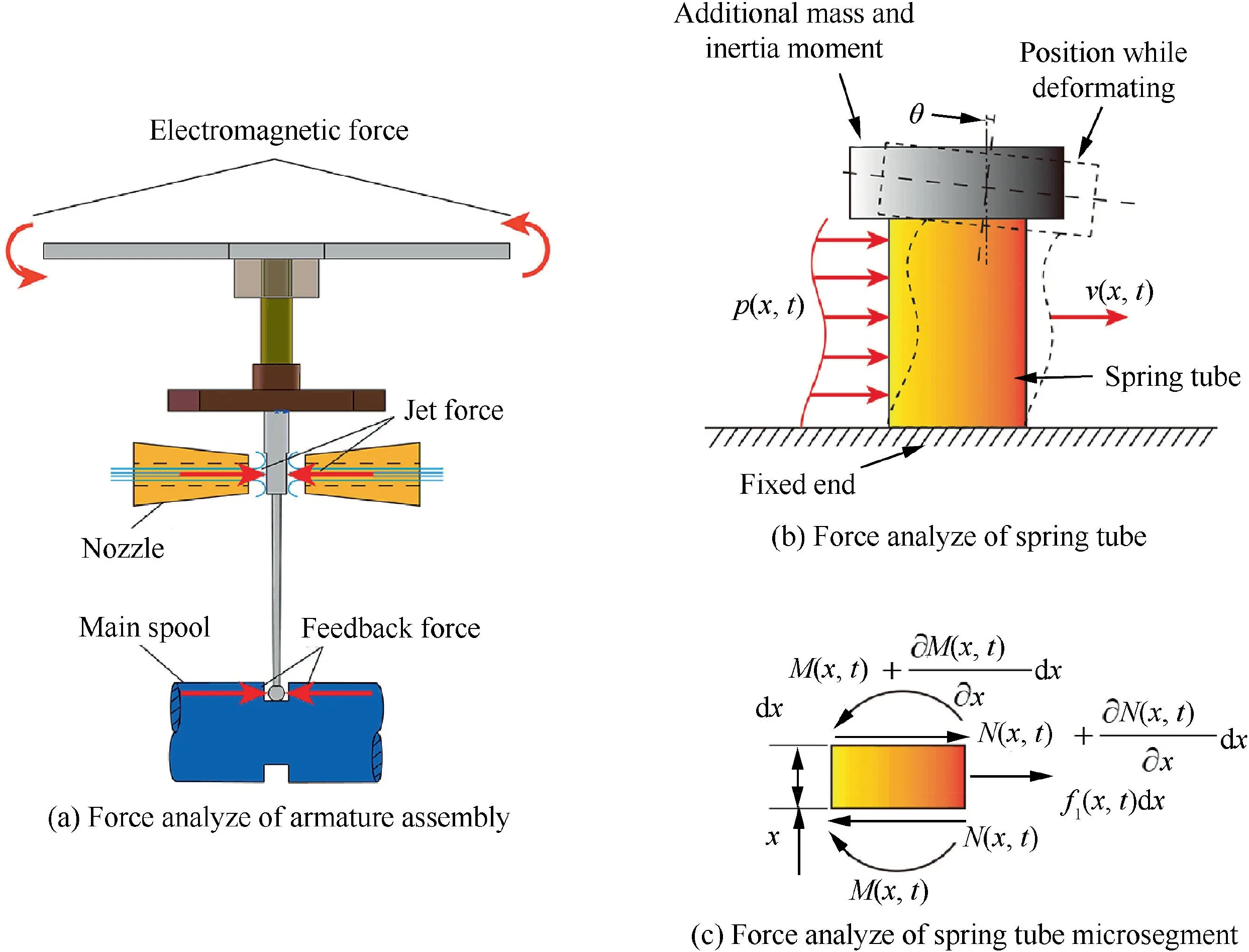
Fig. 2 Force analysis of spring tube.
Based on the distributed parameter method,the force analysis of the spring tube is also shown in Fig. 2(b).p(x ,t) is the transverse load over time and x coordinate, v(x ,t) is the function of tangential deflection. With the DPM, the deformation of different spring tube position can be calculated by the partial differential equations, and the process of discretizing the structure is omitted compared with the FEM.
For the distributed parameters model, to establish the partial differential equations of motion according to the force analysis of spring tube microsegment as shown in Fig. 2(c),the force equilibrium equation for each microsegment can be expressed as28
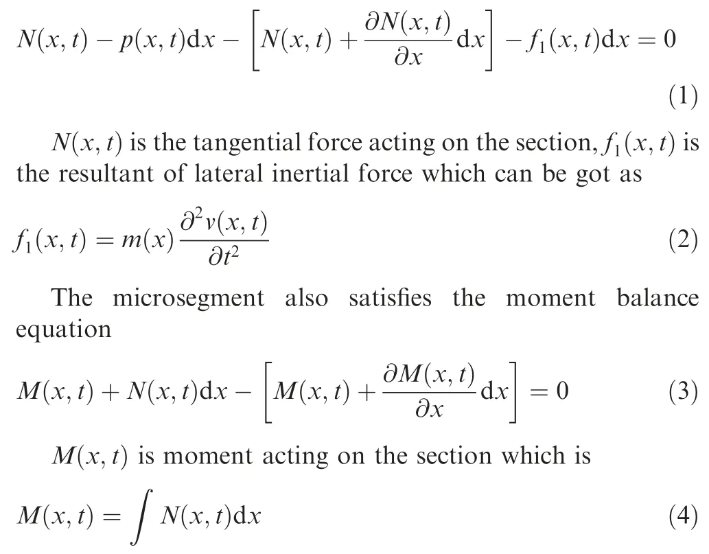
By Combining Eqs. (1) and (3), the partial differential equations for the bending motion of the spring tube can be obtained as

where EI(x ) is the bending stiffness, m(x ) is the mass per unit length.
With the partial differential equation of motion, the undamped mode and frequency of the spring tube can be calculated when p(x ,t)=0. With simplifying we get

EI and m become constant if the shape and material of the spring tube remain unchanged. Using the separated variable method, the function of tangential deflection can be expressed as

where φ (x ) and ψ( t ) are the modal eigenfunction and modal mechanical response expressions.
The general solution of spring tube vibration mode can be obtained by substituting the Eq. (6) with Eq. (7), which is

where a is equal to

where ω is the natural frequency of the spring tube.
From Fig. 2, the boundary condition for the equation can be known as


where mfand jfare the additional mass and inertia moment of the flapper and the feedback rod respectively,L is the length of spring tube,the subscript s represents the spring tube,the subscript f represents the flapper and the feedback rod.
Substituting Eq. (10) into Eq. (8), we get
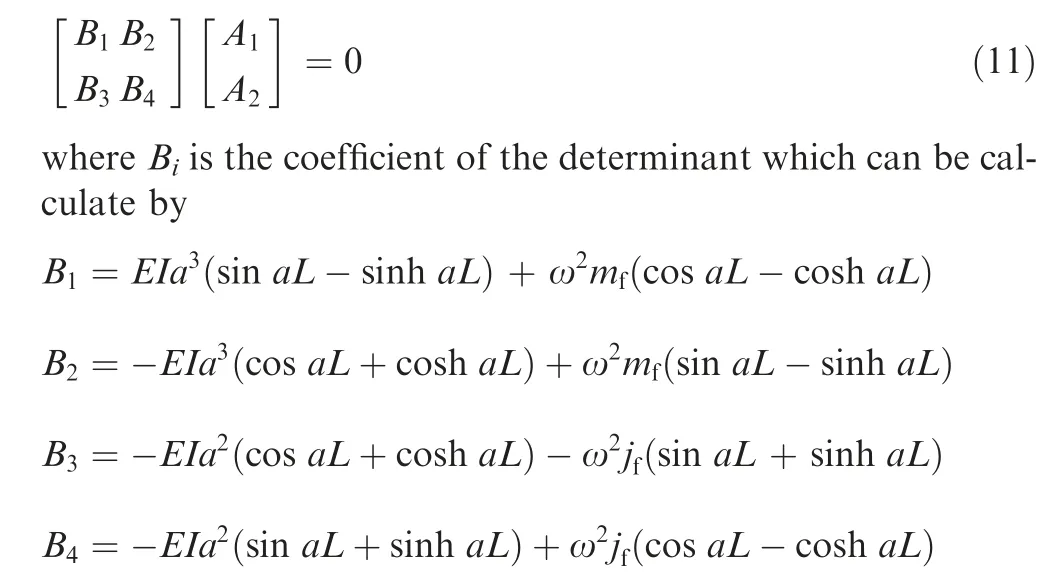
The natural frequencies of the spring tube can be solved when the determinant value of Biis zero, and it also ensures the value of A1and A2won’t be zero simultaneously. Since the solving equation is transcendental, it is impossible to obtain the analytic solution of the natural frequency directly.By using Matlab program to calculate the determinant value of the matrix based on the Armature assembly properties listed in Table 1, and the point changing the sigh of determinant value is obtained and the corresponding natural frequencies of the spring tube are obtained as listed in Table 2. The distributed parameter method has infinite modals in principle,the deformation shape of the spring tube will be dominated by a certain modal when the operating frequency of spring tube is close to the frequency of this modal. The working frequency of the servo valve won’t exceed 1000 Hz,which is much lower than the first-order natural frequency of the spring tube.Therefore, only using the first-order modal to simulate the dynamic response of the spring tube is sufficient to meet the accuracy requirements.
With the natural frequency,the modal eigenfunction can be obtained as


Table 1 Armature assembly material properties.
Each value of A1corresponds to a specific ψ(t ).To simplify the calculation, A1takes the value of 1 in subsequent calculations.
By determining the modal eigenfunction of the spring tube,the modal mechanical response expression can be obtained by the Hamilton principle which means the variation of total system energy should be zero in any time period. The classic expression of Hamilton principle is
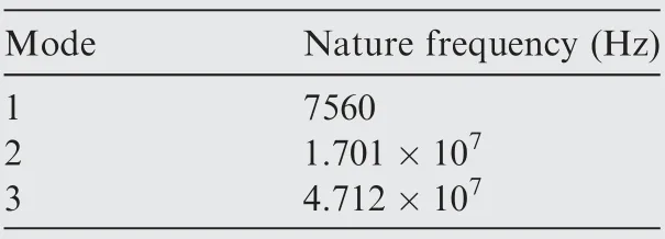
Table 2 .Nature frequency of spring tube.

where T and V are the kinetic and potential energy of entire system respectively, W is the energy generated by the external force.
Before applying the Hamilton principle to simulate the dynamic response of the armature assembly, each energy expression of the system should be listed. The kinetic energy of the spring tube and the other armature assembly can be expressed as

where ρk is the mass per unit length of the spring tube,v and w are the translational velocity along the tangential and rotational angular velocity of the armature assembly respectively,and vyrepresents the velocity along the vertical.
The potential energy of the spring tube and the other armature assembly can be expressed as

where dsis the thickness of the spring tube, R and υ are the bending radian and Poisson’s ratio of the spring tube respectively. hfis the gravity center height of the other armature assembly whose cardinal plane is the fixed end of itself.
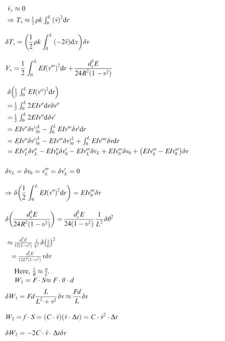
After variating and simplifying Eqs. (14)-(17), we can get Eqs. (18)-(23), and the derivation process is shown in the appendix.
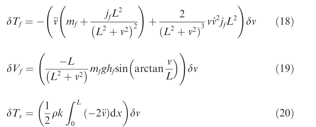

where W1and W2is the work done by the driving and damping force respectively,F is the resultant which includes the diving and damping force,S is the distance of the force acting.d is the distance between the point of action and the center of the armature rotation,c is the viscous damping coefficient taken to be 0.03 according to the experience.
Substitute Eqs. (18)-(23) into Eq. (13), we get

After simplification,the modal mechanical response expression of the spring tube can be obtained by

The expressions of the parameters in Eq. (26) can be obtained as
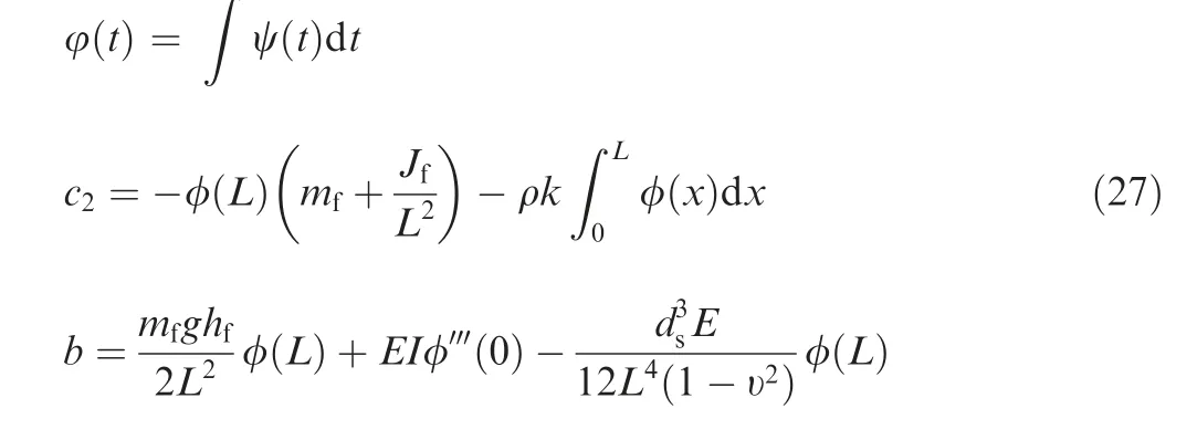
By the Eqs.(12)and(26),the DPM of the armature assembly is completed,by which the deformation distribution of the armature assembly can be calculated. The program of this mathematical model is written by Matlab 2017.
4. Numerical simulation verification
In order to verify the validity of the DPM for the servo valve armature assembly, the dynamic response of the armature assembly under the same working conditions is simulated by FEM and CM of the servo valve.The verification is composed of comparing the numerical simulation results of the DPM,FEM and CM methods.
4.1. Mathematical modeling for classical model
The mathematical model of the CM can be obtained by

where Tdis the driving torque,Jfand Bfare the inertia moment and viscous damping coefficient of the flapper and the feedback rod, Ksis the stiffness of spring tube.
The value of Jfand Bfare determined with the previous work,Ksis set as 68.9 according to the previous research when the distance between the rotation center of the armature assembly and the center of the magnetic pole face is 16.75 mm.29With the program written in Eq. (28), the dynamic response of armature assembly is simulated by the CM.
4.2. Finite element model verification
The 3-dimensional FEM model and mesh structure of the servo valve armature assembly is established as shown in Fig. 3(a). The bottom of the spring tube is set as a fixed end support according to the working conditions.The driving force generated by the electromagnetic is simplified as a couple acting on the armature as marked in Fig. 3(a), and the attribute parameters of the armature assembly are set according to the Table 1.The dimensions of the armature assembly are plotted as Fig. 3(b).
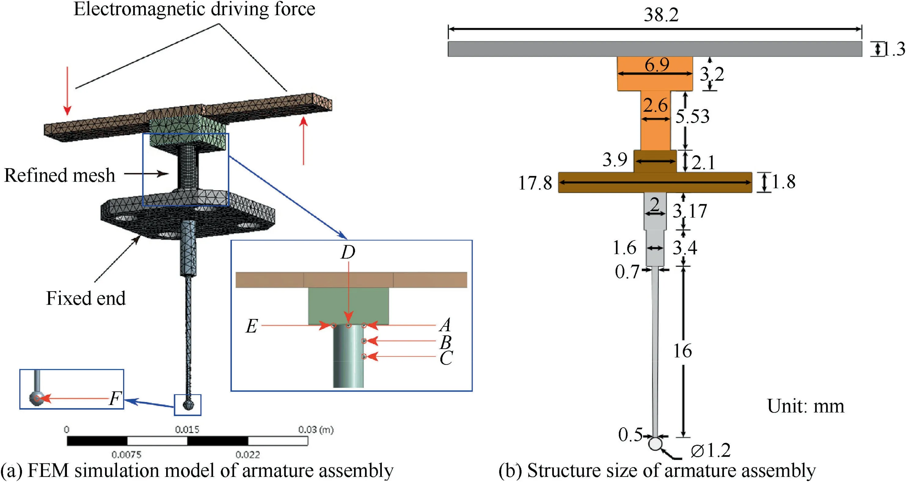
Fig. 3 Mesh and structure of armature assembly.
In order to compare the deformation of the armature assembly at different positions, different points are selected located on the armature assembly. Since the deformation mainly occurs in the spring tube, the locations of the contrast point are predominately selected on the spring tube as shown in Fig. 3(a). The vertex (point A), the point whose height is three quarters of the vertex (point B), midpoint (point C) of one side on the spring tube, the median vertex of the spring tube (point D) and the vertex of the other side (point E) were selected for comparison. At the same time, the bottom of the feedback rod (point F) is also selected to verify the deformation of the other rigid armature assembly.
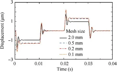
Fig. 4 Deflection curves of different mesh size.

Table 3 Balanced positions of different size mesh.
As the deformation of the spring tube is more obvious compared with the other parts, the mesh of the spring tube is refined. To verify the mesh independence of the FEM model,different size of refined mesh is attempted and the corresponding deflection of the spring tube top along the x-axis direction is plotted in Fig.4.The driving force is the square wave signal whose amplitude and frequency are tentatively set to 0.02 N and 25 Hz according to the actual working condition of the servo valve. The deflection of the spring tube top with a mesh size of 2 mm is clearly different from the curves of other mesh sizes. To make the difference more intuitive, the balance positions predicted by different mesh sizes when the signal just acting on the armature are listed in Table 3, which also shows their errors. Excluding the 2 mm grid with large distinction,the errors of remaining mesh sizes are within 4%. Therefore,to seek a balance between the numerical simulation accuracy and the computational recourses, the mesh size of 0.2 mm is selected in the subsequent numerical simulation process.
4.3. Distributed parameters mathematical model verification
After confirming the validity of the FEM,the numerical simulation results of DPM, FEM and CM under the same condition are compared to verified that the distributed parameter mathematical model can effectively predict the transient response of the armature assembly. The deflection curves of point A, B and C are shown in Fig. 5 with the same driving force as before. The tangential deflection of point A, B and C are plotted in Fig.5(a),and their axial deflection are plotted in Fig. 5(b), the height represents the different position of the spring tube. As the driving force acting on the armature, the dynamic response loci of the three models are the same in predicting the tangential deformation, they both experience the fluctuations and reach the equilibrium position until the driving force changes its value. The fluctuation period and duration predicted by FEM and DPM are basically the same, but that of CM is different.The fluctuation duration of CM is less than that of FEM and DPM by 3.6 ms when the remaining two methods last 5.5 ms. The equilibrium positions are also distinguishing, the precision of CM method is unstable at different positions of armature assembly,the biggest error generates by 81%at point C comparing with FEM and the least one generates at point B with 8.5%.The distinction between DPM and FEM is much less, the smallest one is at point A, with a value of 0.5%, and the largest error occurs at point C where the position predicted by DPM is higher than FEM by 10.3%.
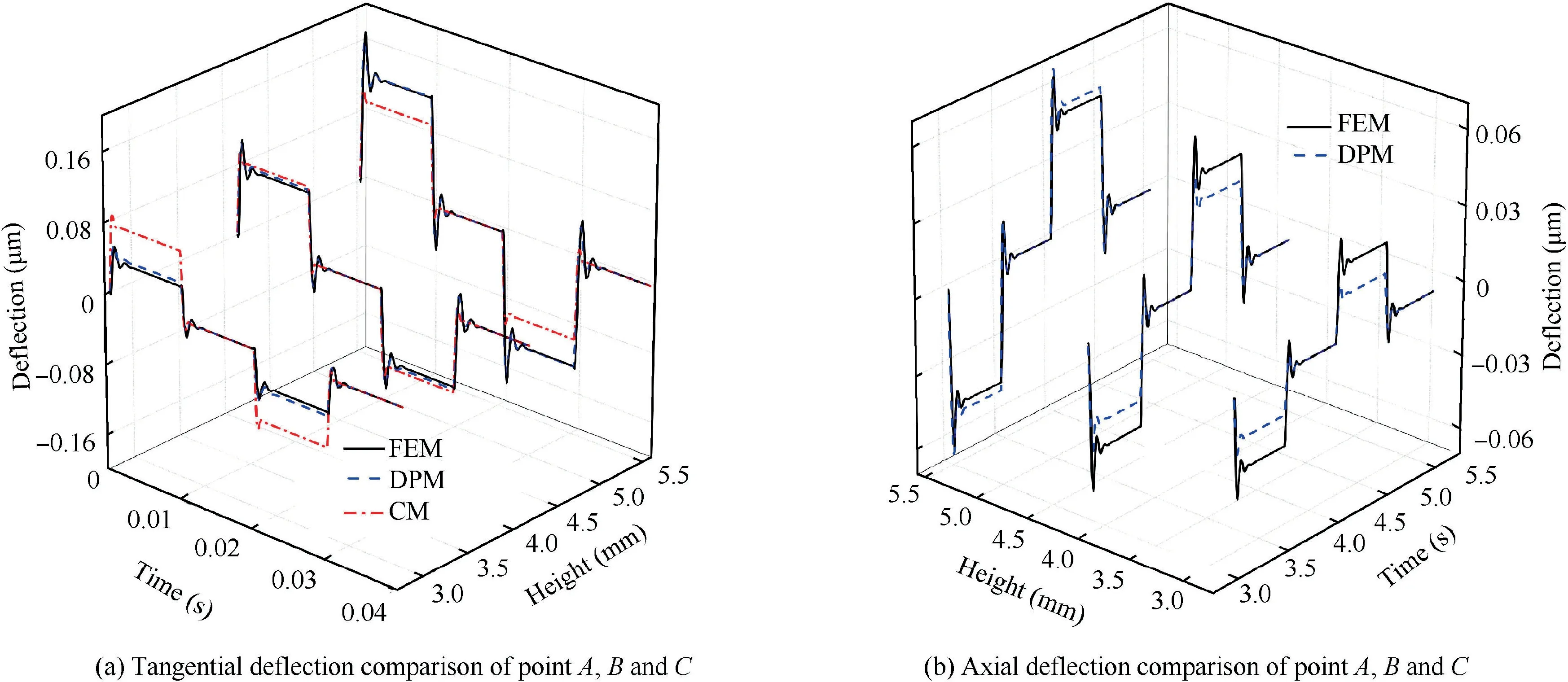
Fig. 5 Tangential and axial deflection of point A, B and C.
Comparing with the tangential deflection, the axial deflection error of point A, B and C is more obvious while the tendency of the fluctuation remains the same. The main purpose of the CM is to obtain the angle of armature assembly and the real-time location of the flapper and feed back rod. Theaxial displacement of the armature assembly at different positions is not the focus of CM,which induces a large error when predicting the axial deformation of the spring tube. The comparison results of the balance position calculated by the three model are listed in Table. 4. Obviously, the CM model is not sensitive to the axial deformation of the spring tube at different positions. Therefore, the CM model is no longer considered when comparing the axial deformation of the spring tube.Observing the axial deformation simulation results of the FEM and DPM as shown in Fig. 5(b), the smallest error occurs at point A with 6.6%, and the error of point C is the maximum, which is 41.1%. This error may be caused by that the DPM method uses an approximate method to simulate the torsion of the spring tube, by which the axial deflection of the spring tube at different heights is calculated according to the tangential vibration modal.

Table 4 Comparison results of balanced positions along axial direction.
Hence, besides a certain error in predicting the axial deformation of the position near the half height of the spring tube,the other simulation results can verify the validity of DPM method in predicting the dynamic response of the different heights on spring tube. Comparing with the CM, the DPM method is more adaptable when predicting the dynamic response along different directions at different positions of the spring tube.
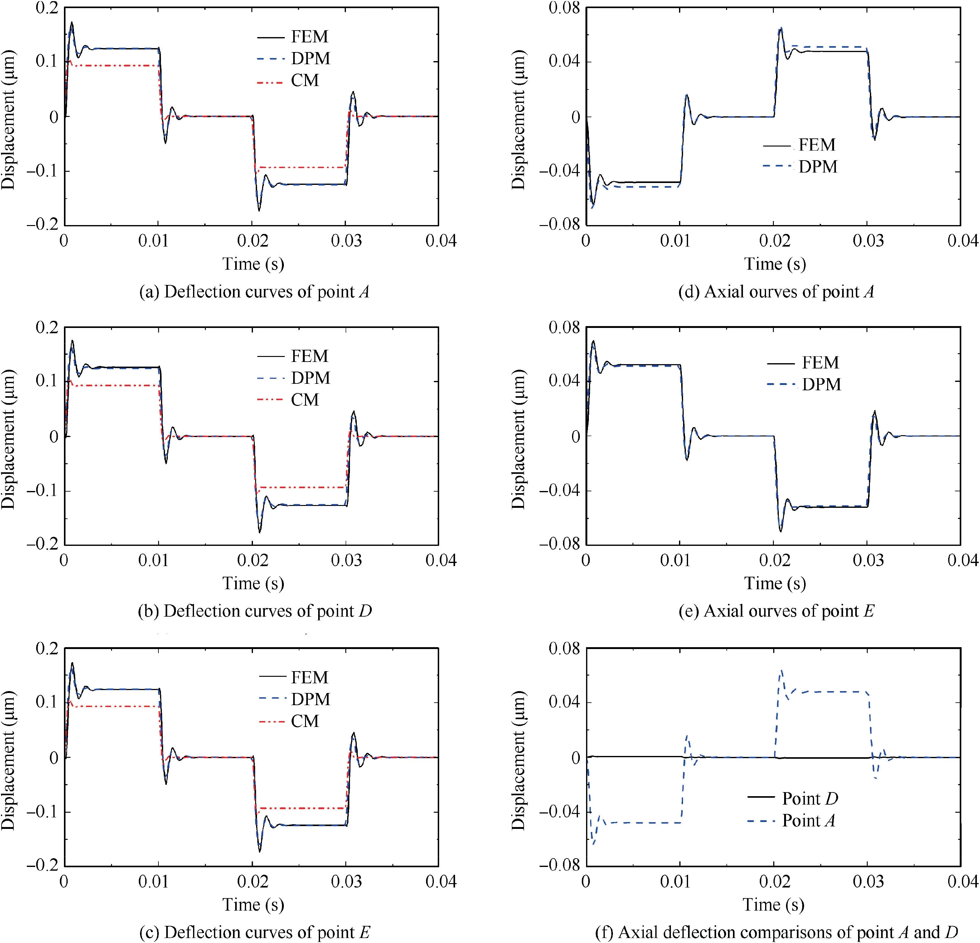
Fig. 6 Tangential and axial deflection of point A, D and E.
After ensuring the accuracy of the mathematical model in predicting the dynamic response at different axial position,the effectiveness of the model at different tangential positions also needs to be demonstrated. The deflection curves of point A, D and E are plotted in Fig. 6. The tangential deflection of point A, D and E are plotted in Fig. 6(a), (b) and (c), and the axial deflection of point A and E are plotted in Fig. 6(d)and(e).As can be seen,the DPM method is relatively accurate in predicting the tangential and axial deformation trajectories of the top section on spring tube. The maximum error occurs at point A, which is 6.6% in predicting the equilibrium position of the axial deformation,and the error of remaining comparisons are less than 2% comparing with FEM. The CM method assumes that the tangential deformation of the same cross section is invariable, which led to a same tangential deformation of points A, D, and E predicted by CM with the error of 25%.
Since the DPM method assumes that no axial deformation is generated along the center line of the spring tube, the comparison of the axial deformation at point D is absent.The axial deflection comparisons of point A and D obtained by FEM are shown in the Fig. 6(f). Comparing with point A, the axial deflection at point D is less than 1% which can be neglected,and by that, the assumption of DPM is verified.
Predicting the transient response of the feedback rod end is also one of the key functions of the armature assembly mathematical model. The tangential deflection comparisons of the feedback rod end obtained by the three methods are plotted in Fig. 7. The process of the deformation is the same as that of the spring tube, which reaches equilibrium position after experiencing fluctuations. The shape of the curves predicted by the three methods are similar except for the amplitude and duration of fluctuation. The error between the DPM and FEM in predicting the equilibrium position is only 1.8%. Since the DPM assumes that the feedback rod and armature is a rigid body which only rotates and translates during the vibration process,which may ignore the deformation of some armature assembly parts and lead to the same equilibrium position but different fluctuation amplitude of the two curves.Comparing with DPM and FEM,the simulation result predicted by CM has less amplitude and duration of fluctuation which is the same as the comparison results of the spring tube deformation.
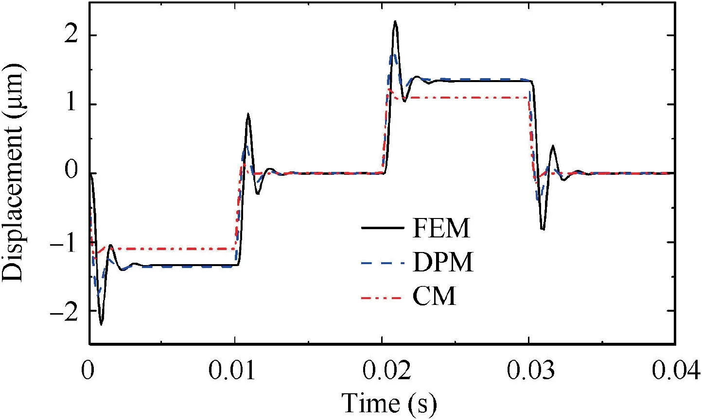
Fig. 7 Axial deflection of point F.
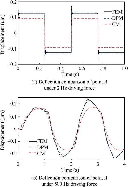
Fig. 8 Deflection of spring tube top at different frequencies.
To further determine the application scope of the DPM,different vibration frequency of the armature assembly is simulated by the three methods.The tangential deflection comparison of the spring tube top with vibration frequencies of 2 Hz and 500 Hz which exceeding the working frequency of the servo valve are shown in Fig. 8 (a) and (b). The deflection curve of 2 Hz is similar to that at 25 Hz, the curve reaches a balanced position after a small fluctuation when the driving force changes its magnitude. The equilibrium position prediction has a certain error of 3.3%between FEM and DPM while that of CM is obviously lower by 25%.When the frequency of the driving force rises to 500 Hz,the armature assembly cannot reach the equilibrium position when the driving force changes its magnitude,and the shape of the deflection curves alters to a sinusoidal one. Except the height of the first crest is basically the same, the subsequent vibration crest predicted by the CM method is significantly lower than the other two methods by 20.89%. Compared with DPM, the deflection curve of FEM has a short time lag after the driving force converting its direction. This is because that the FEM method needs to gradually change the force when the driving force changing its direction. Excluding this lag, the deformation curves predicted by DPM and FEM are basically the same. Therefore,the distributed parameter mathematical model can effectively predict the transient response of the armature assembly at different vibration frequency.
5. Conclusion
In this work, the distributed parameters mathematical model of the armature assembly in the pilot stage of the nozzleflapper servo valve has been established according to the working condition. In order to verify the validity of the mathematical model, the transient response of the armature assembly is simulated by DPM,FEM and CM,and the comparison is discussed.Based on those results,the conclusions can be drawn as follows:
(1) Based on distributed parameters method, the armature assembly is simplified according to its structure, and the natural frequency and modal eigenfunction of the spring tube tangential deformation with additional mass and additional inertia are derived.
(2) With the modal eigenfunction, the modal mechanical response expression of the spring tube is obtained by using the Hamilton principle, and the distribution parameters mathematical model of the armature assembly transient response is established after considering the influence of the armature,flapper and the feedback rod.
(3) The DPM is verified that is accurate enough to predict the tangential deflection of different spring tube positions by the comparison between the three methods of FEM, DPM and CM. An approximate method is applied to simulated the axial deformation of the spring tube by DPM with the error of 6.6% at the top of the spring tube.By comparing the deflection of the feedback rod end predicted by the three methods,the effectiveness and superiority of the DPM method in predicting the transient response of the armature assembly at different positions is verified.
Declaration of Competing Interest
The authors declare that they have no known competing financial interests or personal relationships that could have appeared to influence the work reported in this paper.
Acknowledgement
The work represented in this paper is supported by National Natural Science Foundation of China (No. 51675119).
Appendix.

 CHINESE JOURNAL OF AERONAUTICS2021年3期
- CHINESE JOURNAL OF AERONAUTICS的其它文章
- Criteria for hypersonic airbreathing propulsion and its experimental verification
- Effect of scavenge port angles on flow distribution and performance of swirl-loop scavenging in 2-stroke aircraft diesel engine
- Ship detection and classification from optical remote sensing images: A survey
- Variational method based robust adaptive control for a guided spinning rocket
- Inertial parameter estimation and control of non-cooperative target with unilateral contact constraint
- Theoretical modeling of vectoring dual synthetic jet based on regression analysis
